


Servicios Personalizados
Revista
Articulo
 Inglés (pdf)
 Artículo en XML
 Referencias del artículo
 Enviar artículo por email
Indicadores
-
 Citado por SciELO
 -
 Accesos
Links relacionados
-
 Similares en
SciELO
Similares en
SciELO
Compartir

 Permalink
Superficies y vacío
versión impresa ISSN 1665-3521
Superf. vacío vol.26 no.1 Ciudad de México mar. 2013
Design of capacitive MEMS transverse-comb accelerometers with test hardware
Ibarra-Villegas F. J.*, Ortega-Cisneros S.*, Sandoval-Ibarra F.*, Raygoza-Panduro J. J.**, Rivera-Domínguez J.**
*Centro de Investigación y Estudios Avanzados (CINVESTAV) del Instituto Politécnico Nacional Av. del Bosque #1145, Col. el Bajío, C.P. 45019, Zapopan, Jalisco, México.
**Centro Universitario de Ciencias Exactas e Ingenierías (CUCEI) de la Universidad de Guadalajara Blvd. Marcelino García Barragán #1421, Col. Olímpica, C.P. 44430, Guadalajara, Jalisco, México.
Recibido: 27 de septiembre de 2012
Aceptado: 18 de enero de 2013.
Abstract
This paper proposes the design of MEMS accelerometers, which include hardware to perform testing in a relatively simple way, with different manufacturing processes, PolyMUMPs™ and SUMMiT V™ of MEMSCAP and Sandia Labs respectively, using a methodology that allows them to be adapted to any of these technologies. This method was created to provide the basis to the designing of micro electromechanical devices, optimizing the learning time. The sensors are one-axis transversal comb accelerometers which use an interdigital capacitors array to measure the capacitance change among three independent comb arrays when the system is exposed to positive or negative G forces. In addition, it includes another set of combs which interact as test devices, due to the fact that a voltage can be applied, which will create an electric field in the electrodes of these combs, producing an attraction force that will shift the mobile mass of the sensor, emulating an acceleration to which the device is exposed.
Some physical parameters and dimensions proposed for this accelerometer are presented to show the design methodology of such devices. The accelerometers were designed under constraints set by the manufacturing regulations of PolyMUMPS and SUMMiT V™ The accelerometer layouts were designed using MEMS PRO v4.0™ and AutoCAD® and both were simulated with ANSYS Workbench®.
Keywords: Micro-electromechanical systems (MEMS), accelerometer, capacitive, transverse comb.
1. Introduction
The use and inclusion of inertial sensors, such as accelerometers and gyroscopes, has expanded significantly in recent years in automotive applications, mobile devices, computers, global positioning systems (GPS), video games, aerospace equipment, and biomedical sensors, among many other applications. In the automotive area, the best example of the use of these devices is the sensor that detects a deceleration caused by a crash, which activates the ejection system of air bags in order to save the lives of passengers [1]. In smart phones (Smart Phones) and GPS, the use of these sensors has become very popular for detecting the rotation of the device, adjusting the screen for better viewing, and also to turn the device off when it is dropped, protecting the internal components [2]. For video games, these devices are used as proximity or motion sensors such as in the case of the Wii™ console remote control. In the biomedical field, accelerometers and gyroscopes have been used to measure the ability of motion or rotation of a joint [3], among other important applications [4].
The contribution of this project is the proposal of a methodology for MEMS accelerometer design adaptable to any manufacturing process and the inclusion of test hardware to perform the verification of the sensor [5].
2. Description
The transverse comb accelerometer with test system consists of a set of electrodes, which function as capacitors (sensor electrodes), and another set that operates as actuators to emulate the acceleration (testing electrodes) [6]. A common pattern is to put three sets of combs, even for the sensor part and the testing part. One of those combs is mobile and the other two are fixed so that the capacitors are placed in an interdigital array [7]. In addition, the movable mass has two springs on each side to allow flexibility and stability to the system (Figure 1).
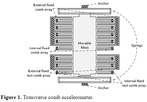
If there is acceleration in the axis to measure, the movable mass will move and the movable comb electrodes will be close to the electrodes of one of the fixed combs, while removed from the other fixed comb. This causes the capacitance to increase between the movable comb and the first fixed comb while decreasing with the second one [8]. This change in capacitance can be measured and converted into an electrical signal, representative of the acceleration to which the system is exposed. The acceleration can be emulated through the testing combs that actuate, moving the central plate and the movable electrodes in one direction as if the accelerometer were under acceleration. The testing combs will allow us to perform the characterization of the accelerometer with much less sophisticated equipment than if they were not available.
3. Design Methodology
This design method can be used with any manufacturing technology, taking into account the constraints that each presents [9]. The method begins by proposing the desired capacitance for each pair of electrodes and the separation between them (Figure 2). This is in order to calculate the length of the electrodes (le) from the equation of the capacitance (Equation 1), where the area (A) is directly proportional to the product of the length by the height (he) of the electrodes. The height depends on the layer width with which the electrodes are constructed, according to the manufacturing process. The separation between the electrodes (d) must also be proposed, following the constraints dictated by the selected MEMS technology. The vacuum permittivity is used as an absolute, as the dielectric material between the electrodes is air and its absolute permittivity is practically the same as its vacuum permittivity (ε=8.85x10⁻¹² F/m).


The capacitance between a movable electrode and two of the fixed electrodes is the same when the system is at resting state. Then the total system capacitance between the movable comb and each of the fixed combs arrays is calculated by multiplying the capacitance of one capacitor by the number of electrodes held by each comb (Ne) (Equation 2).

When the accelerometer is designed, it is useful to indicate at the beginning what is the maximum distance that the movable mass will move. When the mass moves over the axis to be measured, one of the capacitors increases its capacitance while the other one decreases. This change in capacitance is what should be measured by some method to get a signal which is proportional to the acceleration to which the system is exposed. The difference between these capacitances (ΔCT) can be determined from Equation 3, where Δd is the displacement of the movable mass.

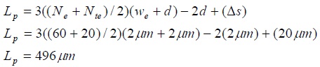
The next step is to calculate the proportions of the central plate of the movable mass. The length of this central plate (Lp) can be calculated with Equation 4, which was obtained specifically for this accelerometer model, where we is the width of the electrodes and must be proposed by the designer, taking into account the design rules of the manufacturing process and Nte is the number of testing electrodes. The separation between the sensors and test combs (Δs) must be proposed.
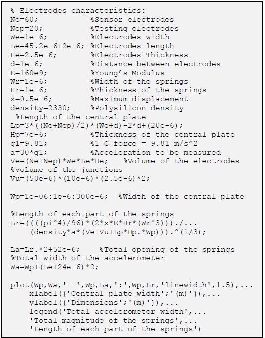
MATLAB® code:

In the last equation the number of electrodes (Ne +Nte) must be multiplied by three, because there are three combs per side with the same number of electrodes. Furthermore, the total number of electrodes must be divided by two because these are equally distributed on both sides of the central plate. The total number of electrodes per side is multiplied by its width (we) and by the separation between them (d). To this magnitude is subtracted two times the separation between electrodes (d) because the last electrodes of the sensing and testing combs are not separated from another one. Finally, the separation between sensing combs and test combs (Δs) is added to obtain the total length of the central plate (Lp) (Figure 3).

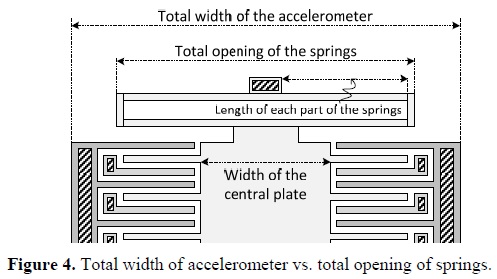
The width of the central plate (Wp) must also be proposed by the designer. However, this variable affects the final magnitudes of the springs and the total width of the accelerometer (Figure 4). The larger the width of the central plate the larger the total width of the accelerometer and the smaller the magnitude of the springs.
After that, the spring constant (k) of the system must be calculated (Equation 5), so that according to a given acceleration (a), a proportional movement on the mass exists, which will result in a difference in capacitance. The acceleration that these devices can measure is given in G-forces.

where F is the force that the movable mass (m) receives due to acceleration (a). The constant δ is the density of the material from which the accelerometer will be built (2330kg/m3 for polysilicon and 19300 kg/m3 for gold). The variable x is the maximum displacement of the movable mass. VM is the volume of the movable mass, which is composed of the volume of the electrodes (Ve), the volume of the junctions between the springs and the movable mass (Vu), and the volume of the central plate (Vp) (Figure 5). Lp, Wp and Hp are the dimensions (length, width and thickness, respectively) of the central plate.

The spring constant has to be divided by the two springs that contain the model of the transverse comb accelerometer (Equation 6).

The model of the springs used in this accelerometer consists of four parts for each one, Lr1, Lr2, Lr3 and Lr4 (Figure 6) [10].

If the four sides of each spring were designed so that they had the same length (Lr1 = Lr2 = Lr3 = Lr4 = Lr), the lengths of the four parts of the spring are calculated using the following equation [10]:

By obtaining the lengths of each of the four parts of both springs, the physical design of the accelerometer concludes. Other dimensions needed for the accelerometer will be based on the constraints set by the design guides of the manufacturing processes PolyMUMPs™ [11] and SUMMiT V™ [12], according to the requirements of the designer.
Another important aspect of the sensor is its resonance frequency and sensitivity. The resonance frequency (fr) is a function that depends on the movable mass (m) and the spring constant of the system (kr) (Equation 8) [13].

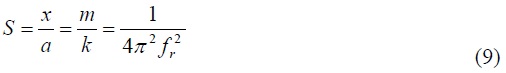
The sensitivity of the accelerometer (S) is defined as the ratio between the displacement of mass and acceleration that the system can measure (Equation 9) [14].
4. Design of a transverse comb accelerometer with PolyMUMPS™
This accelerometer is designed as explained above and following the design rules. The combs, and the springs will be built from a 2µm-thickness polysilicon layer (Poly1) and the movable mass from three layers that will have an overall thickness of 4µm (Poly1, Poly2 and Metal) [15]. The main design specifications are:
• Acceleration to be measured: 0 -30G (1G=9.81m/s2)
• Required capacitance for each pair of electrodes: 1fF
• Distance between electrodes: 2µm
• Number of electrodes per sensor comb: 60 (30 per side)
• Number of electrodes per test comb: 20 (10 per side)
• Maximum displacement of the movable mass (x): 1.85µm
The length of the electrodes necessary to obtain a capacitance of 1fF is calculated from Equation 1:

If every pair of electrodes has a capacitance of 1fF, then each complete fixed comb has a capacitance of 60fF (Equation 2) with respect to the movable comb when the system is resting, because they have 60 electrodes each. When the system is exposed to the maximum acceleration to be measured, the movable mass will move the maximum distance, producing a difference in capacitance of 80fF (Equation 3).
The width of the electrodes is proposed to be 2µm and the separation between the sensors and test combs is 20 µm. The length of the central plate is calculated from Equation 4:
To obtain the width of the central plate and the length of each part of the springs, a program made in MATLAB® from equations 4, 5, 6 and 7 was designed to calculate and graph these dimensions (Figure 7).
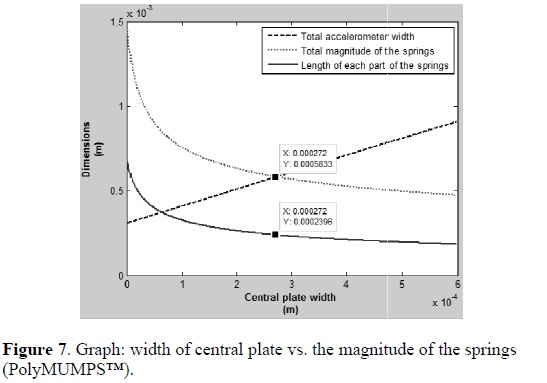
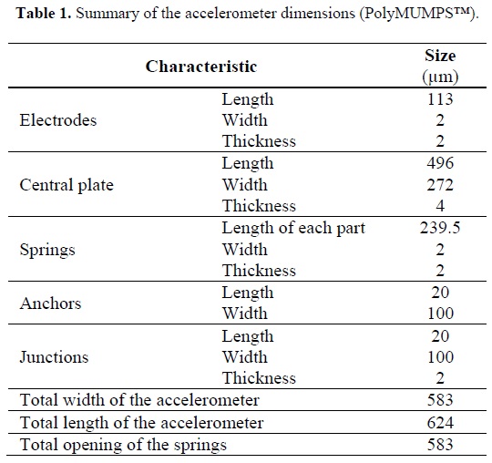
According to the graph in Figure 7, which was generated from the MATLAB® code above, the smaller size of the accelerometer can be obtained if the width of the central plate is proposed to be 272µm. This would ensure that the total width of the accelerometer and total opening of the springs is 583µm. Each part of the springs will be 239.5µm. Taking into account the length of the central plate, the springs and the anchors necessary to support the moving mass, the final device will have a length of 624µm.
The total width of the accelerometer (583µm) considers the anchors to support the fixed electrodes and the gap between them that is 40µm per side (Figure 8), the width of the central plate and the length of the movable electrodes (115µm including a gap of 2µm).

Table 1 shows a summary of calculations and proposed dimensions of each part of the accelerometer, so that it may achieve the specifications listed at the beginning of this section.
The elastic constant of the spring system (k), which was obtained using Equation 5, is 398.74x10⁻³kg/s2. The total mass of the movable mass (m) is 2.506x10_9kg and it was calculated taking into account the volume of the polysilicon parts, the volume of the metal layer in the central plate and the density of polisylicon and gold.
The resonance frequency and the sensitivity of this accelerometer can be calculated from equations 8 and 9 respectively.

4.1. Simulation of the PolyMUMPs™ accelerometer
The accelerometer designed above was modeled and simulated using ANSYS Workbench software. The first simulation shows the total deformation when an acceleration of 30G is applied along the axis to be measured (Figure 9). The simulation shows that the maximum movement of the accelerometer is 1.964µm, which is a valid result within the range of movement that can make the device, as the distance between electrodes is 2µm.

In the next simulation (Figure 10), the locations where the maximum stress is present when an acceleration is applied to the device, can be clearly identified. The maximum stress, according to the simulation, is 19.071MPa, which is under the fracture strength of polysilicon with which the system will be built. That is approximately 1.21 ±0.8 to 1.65 ±0.28GPa according to the PolyMUMPs™ design handbook [11].
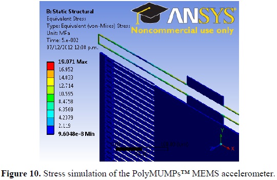
The highest stress occurs at the junctions of the springs with the anchors and the moving mass and the endpoints of both springs.
The last simulation performed to this accelerometer is a modal analysis. This simulation evaluates the response of the structure when it is subjected to vibrations on different directions.
The modal analysis simulation provides the resonant frequencies depending on the direction of vibration. Results of the modal analysis are shown in Table 2. The lowest resonant frequency, according to the results of this simulation, is 1.855kHz. This resonant frequency is approximately equal to the previously calculated (2.007kHz).

4.2. Layout
Figure 11 shows the layout of the accelerometer, which will be built from a top metal layer of 0.5µm thick, two polysilicon layers, POLY1 and POLY2, with 2µm-thickness and 1µm-thickness respectively, on another polysilicon layer (POLY 0) which serves as ground plane as well as to interconnect the fixed electrodes and for transmitting electrical signals. This layout was drawn using MEMS PRO v4.0™ software.
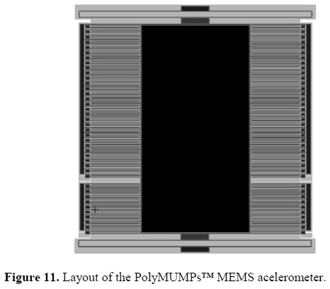
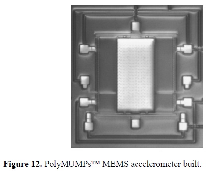
This accelerometer was sent to be built by with the company MEMSCAP. Figure 12 shows the final version of the accelerometer. Pads to connect the accelerometer to a package and to perform tests at the accelerometer are found around the device.
5. Design of a transverse comb accelerometer with SUMMiT V™
This accelerometer was also designed like the previous one, but according to the design rules of SUMMiT V™ manufacturing process. The combs will be built from two polysilicon layers with a total thickness of 2.5µm (MMPOLY1 and MMPOLY2) and the movable mass from four polysilicon layers that will have an overall thickness of 7µm (MMPOLY1, MMPOLY2, MMPOLY3 and MMPOLY4). The main design specifications are almost the same as the last accelerometer, except for the distance between electrodes and the maximum displacement of the movable mass:
• Acceleration to be measured: 0 -30G (1G=9.81m/s2)
• Required capacitance for each pair of electrodes: 1fF
• Distance between electrodes: 1µm
• Number of electrodes per sensor comb: 60 (30 per side)
• Number of electrodes per test comb: 20 (10 per side)
• Maximum displacement of the movable mass (x): 0.5µm Equation 1 is used to get the length of the electrodes necessary to obtain a capacitance of 1fF:

The complete fixed combs have a capacitance of 60fF with respect to the movable comb when the system is at resting state, because each has 30 electrodes per side (Equation 2). When the system is exposed to an acceleration and the movable mass moves 0.5µm, the difference in capacitance is 80fF (Equation 3).
For this accelerometer, the width of the electrodes is proposed to be 1µm, that is because the manufacturing process allows it, and the separation between the sensors and test combs is also 20µm. Equation 4 is used to calculate the length of the central plate:

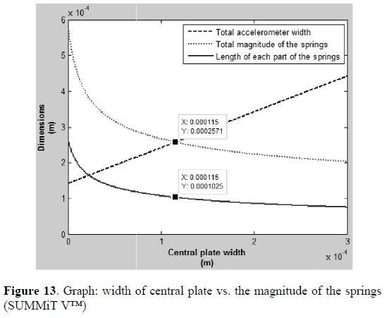
The program in MATLAB® is also used to get the width of the central plate and the length of each part of the springs. Figure 13 shows that the width of the central plate should be 115µm in order to obtain the smaller size of the accelerometer. With this value, the total width of the accelerometer and total opening of the springs is 257µm and each part of the springs will be 102.5µm.
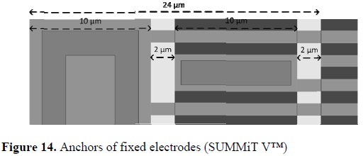
The total length of the device is 524µm, which includes the length of the central plate, the springs and the anchors necessary to support the moving mass. The anchors to support the fixed electrodes and the gap between them have a width of 24µm (Figure 14). A summary of all dimensions of each part of the accelerometer is shown in Table 3.

The mass of the movable bodies was obtained by multiplying the density of the polysilicon by the volume of the movable mass:

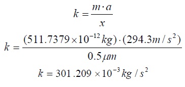
The elastic constant of the spring system can be calculated from Equation 5, using the mass multiplied by the acceleration and divided by the maximum displacement of the movable mass, as shown as follow:
Equation 8 can be used to calculate the resonance frequency of the accelerometer and its sensitivity from Equation 9.


MATLAB® code:

5.1. Simulation of the SUMMiT V™ accelerometer
Similar to the previous accelerometer, the SUMMiT V™ accelerometer was also modeled and simulated using ANSYS Workbench® software. When an acceleration of 30G is applied along the axis to be measured, the total deformation of the device is 0.5687µm (Figure 15). This deformation represents the maximum movement of the accelerometer at that acceleration. The result is valid because it is in the range that the device can move because the distance between electrodes is 1µm.

The stress simulation shows that the maximum stress to which the device is subjected is 12.203MPa, which is under the fracture strength of polysilicon (Figure 16).

Finally, the results of the modal analysis, which are presented in Table 4, show that the lowest resonant frequency is about 3.496kHz and it is very similar to the frequency calculated for this device (3.861kHz).

5.2. Layout
The layout of the accelerometer is shown in Figure 17. This layout was drawn in AutoCAD. The central plate will be built with polysilicon layers 1, 2, 3 and 4 with a thickness of 1µm, 1.5 µm, 2.25µm and 2.25µm respectively. Electrodes will be built with polisilicon layers 1 and 2, and the springs only with polysilicon layer 1, allowing them to have more flexibility.

6. Conclusions
The accelerometers designed in this paper were simulated in ANSYS Workbench® software. The results of these simulations have been very satisfactory according to mathematical calculations, so it is considered that the design methodology proposed in section 0 is feasible to develop this type of MEMS devices, simplifying their design.
The manufacturing processes used in this work have their own advantages and disadvantages in the design of MEMS devices. PolyMUMPs™ is a 2µm, 3-level, surface micromachining technology. This process turns out to be of the cheapest compared to other technologies since it is focused on the area of research in universities, industry and government. A major disadvantage of this technology is that it relies on the restrictions to add or implement different layers or fabrication steps along the construction of the accelerometer structure, so different results can be obtained in the characteristics of the material used in the fabrication line.
SUMMiT V™ process is a 1µm, 5-level, surface micromachining technology. This process has a better resolution and more mechanical layers than PolyMUMPs™, which allows one to obtain smaller devices. Moreover, this number of mechanical layers allows build more complex structures. One disadvantage of this technology is that it is slightly more expensive than that previously described. However, its resolution and construction quality ensure that devices have better performance.
References
[I] D. S. Eddy, D. R. Sparks, International Symposium on Micromechatronics and Human Science, Nagoya, Japan, 1998. [ Links ]
[2] T. Sethuramalingam, A. Vimalajuliet, 2nd International Conference on Mechanical and Electrical Technology, 2010. [ Links ]
[3] M. Mottaghi, F. Ghalichi, H. B. Ghavifekr, International Conference on Microelectronics, Nis, Serbia, 2008. [ Links ]
[4] S. Gervais Ducouret, Sensors Applications Symposium, San Antonio, TX, USA, 2011. [ Links ]
[5] B. Li, D. Lu, W. Wang, Sensors and Actuators, 79, 219 (2000). [ Links ]
[6] B. D. Pant, L. Dhakar, P. J. George, S. Ahmad, Sensors & Transducers, 109, 92 (2009). [ Links ]
[7] F. A. Hassani, A. F. Payam, M. Fathipour, Smart Structures and Systems, Tehran, Iran, 2010. [ Links ]
[8] J. G. Korvink y O. Paul, MEMS: A Practical Guide to Design, Analysis, and Applications, Freiburg, Germany: William Andrew, Inc, 2006. [ Links ]
[9] F. J. Ibarra V., Master Thesis: Guadalajara, Jal., México, 2011. [ Links ]
[10] S. D. Senturia, Microsystem Design, Kluwer Academic Publishers, (New York, USA, 2002). [ Links ]
[11] MEMSCAP, PolyMUMPs Design Handbook, 1992 - 2005. [ Links ]
[12] Sandia National Laboratories, SUMMiT V™ Design Manual, Albuquerque, New Mexico, USA, 2008. [ Links ]
[13] J. J. Allen, Micro electro mechanical system design, (Boca Raton, FL: CRC Press, Taylor & Francis Group, 2005). [ Links ]
[14] S. Baglio, S. Castorina y N. Savalli, Scaling Issues and Design of MEMS, Chichester, John Wiley & Sons Ltd, (West Sussex, England, 2007). [ Links ]
[15] R. Rincón Jara, R. Ambrosio Lázaro, J. Mireles y A. Jiménez Pérez, V Semana Nacional de Ingeniería Electrónica (SENIE 09), Ocotlan, Jal. México, 2009. [ Links ]

