SciELO - Scientific Electronic Library Online

 
vol.24 número3Análisis del sistema de medición por atributos en la inspección de calidad para zarzamoras índice de autoresíndice de materiabúsqueda de artículos
Home Pagelista alfabética de revistas  

Servicios Personalizados

Revista

Articulo

Indicadores

Links relacionados

  • No hay artículos similaresSimilares en SciELO

Compartir


Ingeniería, investigación y tecnología

versión On-line ISSN 2594-0732versión impresa ISSN 1405-7743

Ing. invest. y tecnol. vol.24 no.3 Ciudad de México jul./sep. 2023  Epub 17-Nov-2023

https://doi.org/10.22201/fi.25940732e.2023.24.3.017 

Articles

Analytical formula of the mutual impedance of a partial core transformer with conductive tapes

Fórmula analítica de la impedancia mutua de un transformador de núcleo parcial con cintas conductoras

Cándido Arturo Pérez-Gómez1 
http://orcid.org/0000-0003-3833-2222

Serguei Maximov2 
http://orcid.org/0000-0002-2144-9208

Juan Carlos Olivares-Galvan3  * 
http://orcid.org/0000-0002-1935-2669

Rafael Escarela-Pérez4 
http://orcid.org/0000-0001-7415-3059

1 Instituto Tecnológico de Morelia, Michoacán. Tecnológico Nacional de México. Programa de Graduados e Investigación en Ingeniería Eléctrica. E-mail: cart.gom@gmail.com

2 Instituto Tecnológico de Morelia, Michoacán. Tecnológico Nacional de México. Programa de Graduados e Investigación en Ingeniería Eléctrica. E-mail: sgmaximov@yahoo.com.mx

3 Universidad Autónoma Metropolitana (UAM). Unidad Azcapotzalco. Departamento de Energía. E-mail: jolivares@azc.uam.mx

4 Universidad Autónoma Metropolitana (UAM). Unidad Azcapotzalco. Departamento de Energía. E-mail: epr@azc.uam.mx


Abstract

The present work shows a first approximation of the analytical model of the mutual impedance of a transformer with a partial cylindrical core considering the effective tensor values of magnetic permeability and electrical conductivity. This first model is based on the use of constant values to represent the effective relative permeability of the core material of this transformer. The analytical expressions obtained allow modeling the mutual impedance values for the following cases: filamentary conductor, conductors with a rectangular cross-section and for a two-coil device.

Keywords: Transformer; PCT; mutual impedance; analitycal formula

Resumen

El presente trabajo muestra una primera aproximación del modelo analítico de la impedancia mutua de un transformador de núcleo parcial cilíndrico considerando los valores tensoriales efectivos de la permeabilidad magnética y la conductividad eléctrica. En este primer modelo se considera que el material del núcleo del transformador posee un valor constante de permeabilidad relativa efectiva. Las expresiones analíticas obtenidas permiten modelar los valores impedancia mutua para los siguientes casos: Conductor filamentario, conductores con sección transversal de forma rectangular y para un dispositivo con dos bobinas.

Descriptores: Transformador; PCT; impedancia mutua; fórmula analítica

Introduction

The appearance of new technologies and materials has allowed the development of smaller electrical devices, without compromising their efficiency (Moradnouri et al., 2020). A novel alternative is the use of high critical temperature superconducting materials (HTS) in the design and construction of electric transformers. The discovery of such materials has allowed the development of smaller transformers with less energy losses and higher efficiency (Tixador, 2004; Hott, 2004; Rey, 2015). Most of the studies carried out in this field are mainly focused on the analysis of the full core transformers (Zueger, 1998; Weber et al., 2005). However, the amount of ferromagnetic materials in such cores make the eddy current and hysteresis losses more prominent. For this reason and considering the appearance of superconducting materials, a new type of transformers has been proposed, such as the so-called partial core transformer (PCT). The main characteristics of these transformers is the presence of only one central core made of ferromagnetic material and absence of ``legs" at the ends of the core. A schematic representation of a PCT is shown in Figure 1. The absence of the supports at the ends of the core in PCT's makes the magnetic flux freely continue in the medium surrounding, as shown in Figure 1. The flux passes through the central core and returns back through the medium where the magnetic reluctance is higher. Therefore, the PCT's reluctance is higher compared to that of full core transformers (Lapthorn et al., 2010). Despite the evident advantages that the use of PCTs implies, very few studies have been carried out to investigate their performance (Bodger et al., 2005; Hu et al., 2016).

Figure 1 Partial core transformer 

In this paper, an analytical model for the determination of the mutual impedance of a partial core transformer is presented taking into account the tensor of the core permeability dependent of frequency. The tensor form of the permeability and its dependence of the frequency is due to the laminated structure of the core. The model developed can be used to determine the feasibility of designing PCTs with the use of superconductor tapes in the windings. The presented research establishes bases for further studies in this field.

Model

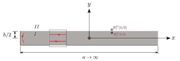
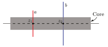
The geometry of the model is shown in Figure 2, where a cylindrical laminated core of a radius R is surrounded by a filament of a radius a located at z1 coordinate counted from the center of the core. The core is considered sufficiently long so that the effects at the ends of the core are neglected. The idea of calculating the mutual impedance is similar to that published in Wilcox et al. (1988), except for the fact that the laminated structure of the core results in the anisotropic effective core permeability and conductivity. These tensorial parameters are properly calculated in the next section.

Figure 2 Laminated core of partial core transformer with filamentary conductor 

The phenomenon is governed by well-known Maxwell's equations with the following tensorial substantial equations:

B=μ-H (1)

Je=σ-E (2)

Where Je is the current density induced in the core in the core (Eddy current), μ- and σ- are the effective permeability and conductivity tensors, respectively. The current in the primary filament is It=I0ejωt and the respective current density is modeled as follows:

J=I0δ(ρ-a)δz-z1eϕ (3)

Where δρ-a and δz-z1 are the Dirac delta functions for the radial and z directions, respectively. eϕ is the unitary vector in the ϕ direction (the use of the cylindrical coordinates is implied). Additionally Er,t=Erejωt, Hr,t=Hrejωt.

Effective permeability and conductivity tensors

The ferromagnetic material that composes each lamination is considered uniform and isotropic, so that the laminated structure of the core is the only cause of the anisotropic property of the core. Then, the orientation of the coordinate system axes shown in Figure 3 yields the diagonal orientation of the tensors μ and σ:

μ=μx000μy000μz

and

σ=σx000σy000σz

Figure 3 Transformer core sheet with a dielectric layer 

To obtain the explicit form of the tensors μ and σ, which is indispensable for further considerations, let us consider the behavior of the electromagnetic field within only one ferromagnetic sheet (region I) and the surrounding it insulator (region II). The ferromagnetic plane sheet is considered of dimensions h×a ×b, where ℎ is the thickness of the lamination and the width and the length 𝑎 and 𝑏 tend to infinity, respectively. The last assumption is a necessary idealization, which in practice means that the thickness is much less than the width and length ha,b. 𝑐 is the thickness of the insulator between two laminations. Figure 3 schematically depicts the system “ferromagnetic sheet-insulator”, where the part in gray corresponds to the conductive sheet and the insulator is drawn in blue. Let us also assume that the gradient of the magnetic field along the axes OX and OZ is small enough in a way that the magnetic field considerably varies on those directions only at distances much greater than the thickness h.

As a result, the dependence of the magnetic field H on the coordinates x and z can be neglected.

Maxwell's equations under the mentioned assumptions and for this geometry can be reduced to the following:

2Hx=jωμ(y)σ(y)Hx2Hy=jωμyσyHy2Hz=jωμ(y)σ(y)Hz (4)

where μy=μ0μr and σy=σ in the ferromagnetic, μy=0 and σy=0 in the dielectric. Equation (4) are considered with the appropriated boundary conditions which are:

HxI±h2=HxII±h2

μrHyI±h2=HyII±h2

HzI±h2=HzII±h2

Figure 4 illustrates boundary conditions for the magnetic field in XOY plane. Red lines represent induced eddy currents.

Figure 4 View of the x - y plane of the transformer core sheet 

As seen in the previous expressions, the boundary conditions for the x - y and z - y planes are similar given the dimensions assumed in the analysis. However, in the x - z the field that is conserved to pass between both media is the B field, so that the assumed boundary condition is the following:

ByI=ByII (5)

Rewriting the above in the form:

μ0μrHyI=μ0HyII (6)

The boundary condition for the 𝑦-component shown is obtained.

The solution to equations (4) within the conductive sheet can be obtained in the form:

Hxy=HxIIcosh(βy)coshβh2inside the sheetHxIIin the insulator                                                  Hyy=HyIIμrinside the sheetHyIIin the insulator                                                                        Hzy=HzIIcosh(βy)coshβh2inside the sheetHzIIin the insulator                                                     (7)

where HxII, HyII and HzII are constants and β=1+jωμσ/2. At the same time, for the field B we get:

Bxy=μ0μrHxIIcosh(βy)coshβh2inside the sheetμ0HxIIin the insulator                                                  Byy=μ0HyIIinside the sheetμ0HyIIin the insulator                                                                                Bzy=μ0μrHzIIcosh(βy)coshβh2inside the sheetμ0HzIIin the insulator                                                          (8)

In turn, the tensor of the permeability can be obtained from the constitutive relation B=μH which in directions OX, OY and OZ takes the form of the following three equations: Bx=μxHx, By=μyHy and Bz=μzHz. Obtained this way permeabilities μx, μy and μz are functions of the coordinate y. Their values change passing from a ferromagnetic sheet to the insulator and from the insulator to the next sheet, etc., performing a rapidly oscillating behavior. In order to represent the laminated core as a continuous medium, it is necessary to consider the so-called average fields B and H. In these terms, the effective permeability of the laminated core as a continuous medium is the relation between the average fields:

B=μ-H (9)

where the average field is obtained according to the following rule. Let Gr be a vectorial field. Then, the average field can be obtained as follows:

Gr=1VVGr+fdfxdfydfz (10)

where the volume V is the minimum necessary to smooth any non-uniformity of the medium. In our particular case the volume V should include a lamination together with one insulating layer, i.e., V=h+c3. As a result, the components of the effective relative permeability tensor can be got in the following way:

μ-x=Bxμ0Hx,      μ-y=Byμ0Hy,     μ-z=Bzμ0Hz (11)

The integration of the fields (8) and (7) according to formula (10) and the substitution of the respective results into (11) finally yields:

μ-x=μ0Fμrtanh(βh/2)βh/2+1-FFtanh(βh/2)βh/2+1-Fμ-y=μ0μrF+(1-F)μrμ-z=μ0Fμrtanh(βh/2)βh/2+1-FFtanh(βh/2)βh/2+1-F (12)

where F is the stacking factor which expresses the amount of metal in the core, given by formula:

F=hh+c (13)

Finally, the sought effective permeability tensor is obtained by substituting the obtained values (12) of the effective permeability into the matrix:

μ-=μ-x000μ-y000μ-z (14)

One can observe in (12) that the obtained permeability tensor depends on frequency in a way that in the high frequency limit ω0 the permeabilities μ-x approach μ-0 because in this limit the depth of penetration of the electromagnetic field into each ferromagnetic sheet tends to zero.

Conductivity tensor

The conductivity tensor σ- can be determined through simple geometric analysis and considering the response of the core to alternating electric field in different directions. First, the conductivity in OY direction is zero, since the dielectric layers between the conductive sheets insulate currents along this axis. In turn, the ferromagnetic sheets conduct electric current in other directions, as shown in Figure 5.

Figure 5. Transformer core conductivity 

Let us consider an alternating electric field in OX direction. The resulting current density distribution within the core can be described as follows:

Jxy=σEx  inside the sheet0       in the insulator (15)

Therefore, the effective conductivity in OX direction can be obtained by applying the same principle described in previous section. In other words, the effective conductance is the relation between the average current density  Jx and electric field Ex:

σ-x=hh+c(σ)+ch+c(0)=F (16)

where it is observed that σ0 in the sheets because it is a conductive medium, while in the dielectric material because there are no circulating currents σ=0.

The same result is obtained in OZ direction. Thus, the effective conductivity tensor takes the form:

σ-=Fσ0000000Fσ (17)

Permeability and conductivity tensors in the cylindrical coordinate system

Although the axial symmetry of the problem is not hold due to the anisotropic property of the laminated core, the use of the cylindrical coordinates is more adequate to calculate the mutual impedance of the transformer with cylindrical core. Therefore, the effective permeability and conductivity tensors (14) and (17) obtained in the flat coordinates should be transformed into the cylindrical coordinate system. This can be fulfilled using the well-known tensorial transformations when passing from one system of coordinates to another.

From the point of view of the tensorial transformations, the transition from the Cartesian coordinate system to the cylindrical is a 2D rotation given by the following unitary transformation matrix:

U=cosϕ-sinϕ0sinϕcosϕ0001 (18)

Then, the effective permeability and conductivity tensors in the cylindrical coordinates can be obtained as follows:

μcyl=U-1μ-andUσ=U-1σ-U

As a result, we get:

μcyl=μ-xcos2ϕ+μ-ysin2ϕμ-y-μ-xsinϕcosϕ0μ-y-μ-xsinϕcosϕμ-xsin2ϕ+μ-ycos2ϕ000μ-z (19)

and

σcyl=Fσcos2ϕ-Fσsinϕcosϕ0-FσsinϕcosϕFσsin2ϕ000Fσ (20)

These tensors finally can be substituted into Maxwell's equations to calculate self and mutual impedance of partial core transformers with cylindrical laminated core.

Nevertheless, the use of these tensors in the solution of Maxwell's equations in the cylindrical coordinate system may lead to certain mathematical difficulties since the axial symmetry is not hold. Then, some approximate methods, such as consecutive approximations, should be used. Within this method, a sequence of approximate solutions which converges to the exact one, is obtained. This sequence can be truncated at a certain term according to a predetermined criterion, leading to a solution that satisfies a required accuracy. The first approximation can be reached by approximating the obtained permeability and conductivity tensors with those averaged over all directions ϕ. The same ideology has been adopted by Wilcox et al. (1988) except for that fact that the considered in that work permeability tensor was constant and the conductivity was assumed isotropic.

Averaging of the tensors (19) and (20) over ϕ implies the integration with respect to ϕ and division by 2π according to the following operation:

μ~=12π02πμcylϕdϕ,  σ~=02πσcylϕdϕ

Thus, applying this operation to (19) and (20) we finally come to the following result:

μ~=μ000μ000μz, σ~=σ000σ000σz (21)

where:

μ=μ-x+μ-y2=μ0Fμrtanh(βh/2)βh/2+1-FFtanh(βh/2)βh/2+1-F+μ0μrF+1-Fμr (22)

and:

σ=σx+σy2=12Fσ (23)

Mutual impedance between two coils

Mutual impedance between two conductive filaments

Once the permeability and conductivity tensors of the core having been obtained, Maxwell's equations for a PCT with a cylindrical core can be properly formulated. These equations con be reduced to only one equation for the angular component of the electrical field Eϕ. This equation is (Wilcox et al., 1988):

1jωμzρ1ρρEϕρ+1jωμ2Eϕz2=I0δρ-aδz-z1+σEϕ (24)

where in the core μz, μ and σ are given in (12), (22) and (23), respectively, whereas μz=μ0, μ=μ0 and σ=0 in air. Equation (24) can be solved by using the Fourier transform with respect to the coordinate z defined as follows:

E^ϕρ,k=-+e-jkzEϕρ,zdz (25)

Then, equation (24) in the Fourier domain becomes:

1jωμzρ1ρρE^ϕρ-k2+jωμσjωμE^ϕ=I0δρ-aδz-z1 (26)

Equation (26) is considered together with the boundary conditions that can be expressed as follows:

E^ϕcore|ρ=R=E^ϕair|ρ=R,H^zcore|ρ=R=H^zair|ρ=RE^ϕcore|ρ=0=0,H^zcore|ρ=0=0E^ϕair|ρ=0,H^zair|ρ=0 (27)

The ordinary differential equation (26) with the boundary conditions (27) can be solved using standard methods of mathematical physics. The solution for each medium can be represented in the following form:

E^ϕcoreρ,k=C1kI1λρ (28)

E^ϕairρ,k=C2kK1kρ-jωμ0I0ae-jkz1I1kρK1ka1-θρ-a+I1kaK1kρθρ-a (29)

Where:

λ2=μzμ2k2+jωμzσ

θρ-a is the Heaviside unit-step function and functions C1k and C2k are presented below:

C1k=-jωμ0I0ae-jkz1K1ka×I1kRK0kR-I0kRK1kRI1λRK0kR+μ0μzλkI0λRK1kR

C2k=jωμ0I0ae-jkz1K1ka×-I0kRI1λR+μ0μzλkI0λRI1kRI1λRK0kR+μ0μzλkI0λRK1kR (30)

Here I0,1x and K0,1x are the modified Bessel functions of the first and second kinds, respectively (Tijonov & Samarsky, 1983).

Solutions (29) and (28) represent the electric field distribution both in the core and air. To calculate mutual impedance between two filaments it is only necessary to use solution (29) in air. Assuming that the radius of the secondary filament is b and b>a and its z coordinate is z2 (Figure 6), the electric field value at the secondary (in the Fourier domain) takes a simpler form:

E^ϕb,k=C2kK1kb-jωI0ae-jkz1I1kaK1kb (31)

Figure 6 Laminated core of partial core transformer with two filaments 

Where C2k is presented in (30). In turn, the electric field in the coordinate domain can be obtained from (31) taking the inverse Fourier transform as follows:

Eϕb,z2=12π-+E^ϕb,kejkz2dk (32)

At the same time, the electromotive force in the secondary filament can be easily calculated:

E=-02πbEϕb,z2dϕ=-2πbEϕb,z2 (33)

Finally, the impedance between two filaments is obtained as a fraction between the electromotive force and the electric current:

Z=EI0 (34)

Thus, the substitution of (31) into (32), (32) into (33) and finally (33) into (34), the impedance (34) can be recast in the following form:

Za,b,z2-z1=ZC+jωLA

Here the inductance in air has the form:

LA=-μ02πabϰKϰ2-1+ϰ22Eϰ2 (35)

Where Kx and Ex are elliptic integrals of the first and second kind, respectively, and also ϰ=4ab/{z2-z12+a+b2}. In turn, the core part ZC of the total mutual impedance is:

ZC=jωμ0ab-+coskz2-z1K1kaK1kb×I1λRI0kR-μ0μzλkI0λRI1kRI1λRK0kR+μ0μzλkI0λRK1kRdk (36)

Mutual impedance between two superconductive tapes

Filaments should be substituted by superconductive tapes in the case of PCTs with the use of superconductor windings. Let us consider two tapes of same cross-section, as shown in Figure 7. A and B are the radii of each tape, whereas D and δ are the length and thickness, respectively. Each tape can be represented as a set of filaments with the density 1/Dδ. In this case, formulas (35) and (36) can be rewritten in the form:

LA=-1Dδ2μ02πAA+δdaBB+δdbzA-D2zA+D2dz1zB-D2zB+D2dz2×abϰKϰ2-1+ϰ22Eϰ2 (37)

ZC=jωμ01Dδ2AA+δdaBB+δdbzA-D2zA+D2dz1zB-D2zB+D2dz2×ab-+coskz2-z1K1kaK1kb×I1λRI0kR-μ0μzλkI0λRI1kRI1λRK0kR+μ0μzλkI0λRK1kRdk (38)

Figure 7 Laminated core of partial core transformer with two tapes of rectangular cross section 

The case of two windings can be easily obtained from (37) and (38) by substituting the dimensions presented in Figure 7 with the new ones and considering the number of tapes in the primary and secondary windings NA and NB, respectively (see Wilcox et al., 1988). The width and thickness of each winding, in this case, can be taken as wA and δA for the first one and wB and δB. Therefore, the density of the number of tapes in each winding is NA/wAδA and NB/wBδB, respectively. New dimensions are also affect the limits of the integrals in (37) and (38).

A particularly interesting case for us is that of two superconductive coils placed one over another coaxially as shown in Figure 8, where zA=zB=z, wA=wB=w. As a result, we can obtain:

LA=-NANBw2δAδBμ02πAA+δAdaBB+δBdbz-w2z+w2dz1z-w2z+w2dz2×abϰKϰ2-1+ϰ22Eϰ2 (39)

ZC=jωμ0NANBw2δAδBπ2-+dksin2kw2k4×aK0kaL1ka+K1kaL0kaa=Aa=A+δA×bK0kbL1kb+K1kbL0kbb=Bb=B+δB×I1λRI0kR-μ0μzλkI0λRI1kRI1λRK0kR+μ0μzλkI0λRK1kR (40)

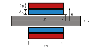
Figure 8 Partial core transformer with two tapes of rectangular cross section placed one over another 

Where L0x and L1x are the Struve functions.

Figure 9 shows the behavior of the resistive and inductive parts of the total mutual impedance of a PCT as a function of frequency, ω, obtained with the analytical formula for the parameters shown in Table 1.

Figure 9 Resistance and inductance between two windings obtain with the analytical model 

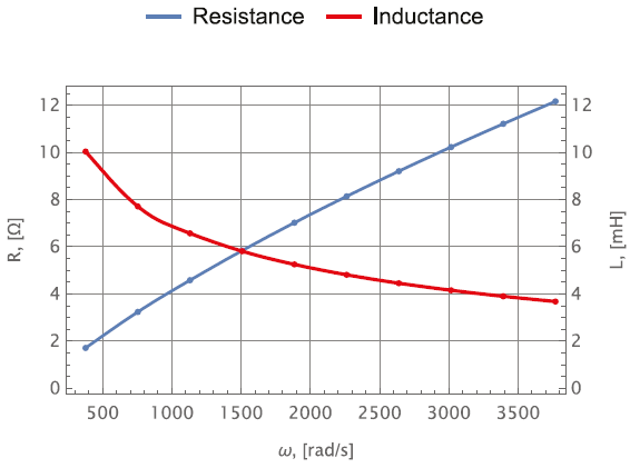
Table 1 Parameter Used in FEM and Analytical Model 

Parameter Value
Core
Length 470 mm
Radius 40 mm
Lamination Thickness 0.23 mm
Material Steel 1010
Inside Winding
Winding Length 338 mm
Wire Thickness 0.305 mm
Current Rating 100 A
Total Turns 320
Material Copper
Outside Winding
Winding Length 330 mm
Wire Thickness 0.305 mm
Current Rating 65 A
Total Turns 320
Material Copper

The analytical model was compared with the finite element method (FEM) using the ANSYS® Maxwell software, the results of which are shown in Figure 10, where it can be seen that the analytical model adjusts well to the values obtained using the FEM. However, the error obtained between both models is around 7 % for the inductance and 11.4 % for the resistance values, this is because the analytical model does not take into account the non-linear characteristics of the core, it must also be remembered that for the analytical model infinite dimensions were considered in the length and width of the sheets that make up the transformer.

Figure 10 Resistance and inductance between two windings obtain with ANSYS Maxwell Software 

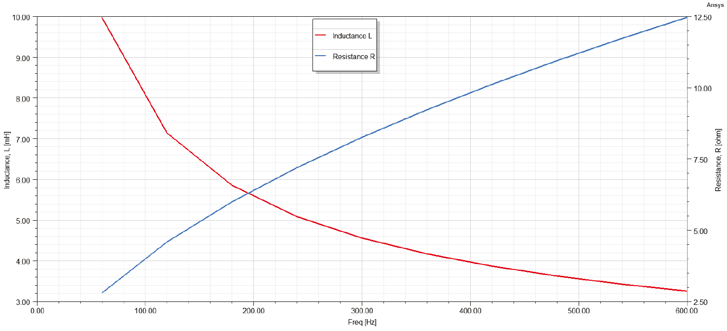
Despite the above, the results obtained show that the analytical model presents a good approximation to the values of resistance and mutual inductance even without considering the non-linear characteristics of the device.

Conclusions

Study of high critical temperature superconductors has allowed the development of a countless number of highly efficient electrical devices with less weight and size. Simpler constructive properties of such devices make them even more beneficent. Partial core high critical temperature superconducting transformers are of that kind. The lack of the external “legs” and the cylindrical geometry of the core make these transformers better candidates for the development of the high efficient power transformers with the size much less than the conventional ones developed up to date. Currently, PTC's are found in resonant transformers or as step-up transformers for capacitive loads (Ming, 2012), but given the characteristics of PTC's, it is possible to manufacture portable step-up/step-down transformers even lighter than those currently on the market. However, research aimed at studying such devices is scarce and only a limited number of models has been developed to study well the achievements of this type of transformers. This paper represented the first analytical approach allowing the determination of the mutual inductance of a laminated partial core transformer, based only on physical and geometrical characteristics of the core and windings. The model properly takes into account the laminated structure of the core. For this purpose, the magnetic permeability and conductivity tensors of the laminated core were obtained as functions of frequency by solving Maxwell's equations within each ferromagnetic sheet. This resulted in additional dependence of the mutual impedance between two windings of frequency. The model was compared with the finite element method using the ANSYS® Maxwell software. This comparison shows that the analytical model obtained is a good approximation for the determination of the mutual impedance of a partial core transformer. However, it is necessary to consider the non-linear characteristic present in this type of devices to have a better fit of the analytical model based on the one obtained through the FEM. Therefore, the subsequent work is to make the model of the non-linear characteristic of the core and add it to the model obtained in this work.

References

Bodger, P., Enright, W., & Ho, V. (2005). A low voltage, mains frequency, partial core, high temperature, superconducting transformer. IEEE Transactions on Applied Superconductivity. [ Links ]

Hott, R. (2004). Application fields of high-temperature superconductors. High Temperature Superconductivity, 2, 35-48. [ Links ]

Hu, D., Sheng, J., Li, Z., Jing, Z., Guo, Q., Hong, Z., . . ., & Yang, H. (2016). Characteristics comparison between HTS air core and partial core transformers. IEEE Transactions on Applied Superconductivity, 26(7), 1-5. http://dx.doi.org/10.1109/TASC.2016.2582682. [ Links ]

Lapthorn, A. C., Chew, I., Enright, W. G., & Bodger, P. S. (2010). HTS transformer: Construction details, test results, and noted failure mechanisms. IEEE transactions on power delivery, 26(1), 394-399. http://dx.doi.org/10.1109/TPWRD.2010.2061874. [ Links ]

Ming-Zhong, B. (2012). Partial Core Power Transformer. Christchurch, New Zealand: University of Canterbury. http://dx.doi.org/10.26021/1995. [ Links ]

Moradnouri, A., Ardeshiri, A., Vakilian, M., Hekmati, A., & Fardmanesh, M. (2020). Survey on high-temperature superconducting transformer windings design. Journal of Superconductivity and Novel Magnetism, 33(9), 2581-2599. [ Links ]

Rey, C. (2015). Superconductors in the power grid: Materials and applications. Elsevier. [ Links ]

Tijonov, A. N., & Samarsky, A. A. (1983). Ecuaciones de física matemática. Moscú: MIR. [ Links ]

Tixador, P. (2004). HTS applications: present and future prospects. High Temperature Superconductivity , 2, 1-34. [ Links ]

Weber, C., Reis, C., Hazelton, D., Schwenterly, S., Cole, M., Demko, J., . . . & Aversa, N. (2005). Design and operational testing of a 5/10-MVA HTS utility power transformer. IEEE Transactions on Applied Superconductivity , 15(2), 2210-2213. https://doi.org/10.1109/TASC.2005.849614. [ Links ]

Wilcox, D., Conlon, M., & Hurley, W. (1988). Calculation of self and mutual impedances for coils on ferromagnetic cores. IEE Proceedings A-Physical Science, Measurement and Instrumentation, Management and Education-Reviews, 135(7), 470-476. https://doi.org/10.1049/ip-a-1.1988.0074. [ Links ]

Zueger, H. (1998). 630 kVA high temperature superconducting transformer. Cryogenics, 38(11), 1169-1172. https://doi.org/10.1016/S0011-2275(98)00104-0. [ Links ]

Cómo citar:

Pérez-Gómez, C. A., Maximov, S., Olivares-Galvan, J. C., & Escarela-Pérez, R. (2023). Analytical formula of the mutual impedance of a partial core transformer with conductive tapes. Ingeniería Investigación y Tecnología, 24 (03), 1-10. https://doi.org/10.22201/fi.25940732e.2023.24.3.017.

Received: August 31, 2022; Revised: November 19, 2022; Accepted: April 25, 2023

* Corresponding author. Juan Carlos Olivares-Galvan. E-mail: jolivares@azc.uam.mx.

Creative Commons License This is an open-access article distributed under the terms of the Creative Commons Attribution License