


 nueva página del texto (beta)
 Inglés (pdf)
 Artículo en XML
 Referencias del artículo
 Enviar artículo por email
 Citado por SciELO
  Similares en
SciELO
Similares en
SciELO 
 Permalink
Introduction
Like other auto parts, the purpose of having a bumper is very specific. This part of the vehicles is a steel, aluminum, rubber, or plastic shield that is mounted on the front and rear of a car. When a low-speed crash occurs, the bumper absorbs the impact to avoid or reduce damage to the car. In some cases, they use energy absorbers or supports, and others are made with a foam material. It is also important to make it clear that car defense is not intended to prevent or reduce damage to occupants, that is what other security systems are for. The design and purpose of bumpers themselves, whatever the material, is to reduce physical damage to the front and rear ends of vehicles in low-speed collisions (Marzbanrad et al., 2009; Sonawane, & Shelar, 2018).
Studies are currently being carried out on new materials and manufacturing processes for the lightening of structures that can be used in the manufacture of vehicle parts. Among these materials is aluminum and its respective alloys.
Aluminum alloys have mechanical properties that make them versatile, relatively inexpensive, and interesting materials, since with these alloys they can be manufactured from very thin ductile sheets used for packaging, to very specific engineering applications such as structures of airplanes, cars, railways, and ships. These manufacturing processes for engineering applications are made by conventional methods such as riveting, screwing, or different welding process like friction stir welding, resistance spot welded, etc. These methods present disadvantages from the mechanical point of view as extra weight in the structure, stress concentrations, corrosion and fatigue crack growth (García et al., 2003; Sun et al., 2016). Many aluminum joining processes for engineering applications require welding. To manufacture a weld with good mechanical properties, it is necessary to select the correct filler metal, perfectly clean the surface of the joints and select the most suitable welding method. There are different fusion welding processes for heat-treated aluminum alloys, unfortunately, by using these methods, the reduction of mechanical properties up to 50 % due to a microstructural transformation caused by the over-aging of the material have been reported (Malin, 1995).
There are studies evaluating the effect of over-aging in welded joints. For example García et al. (2003) has conducted a study where were used Aluminum alloy joints by gas metal arc welding process (GMA). In this case welded joints (6.35 mm thick) Al 6063-T6 plates and single "V" joint using ER-5356 filler wire were manufactured. Findings have reported an average hardness of 54-65 HV in the heat affected zone (HAZ) and 76-82 HV in the fusion zone. In Guzmán et al. (2019) research, 6061-T6 and 6061-T4 aluminum alloys plates (10 mm thick) and single “V” joint welded by pulsed metal transfer GMAW a decrease of hardness was observed (85 HV to 47 HV) generating de HAZ.
The control parameters for the MIG welding process are very important. There are studies where it has been observed that the control of the current, voltage and angle of the torch are very important to achieve a good penetration of the weld. It is mentioned in Patel et al. (1918) that the parameters to obtain a good quality welding are: current of 120 A, voltage of 24 V and the angle of the torch is 90°. In Chikhale et al. (2016) the parameters to obtain a good quality welding are: current of 175 A, voltage of 23 V and the angle and the angle of the torch is 90°.
The welding process involves reaching the melting point of aluminum. Here is another important problem that is the high solubility of Hydrogen in liquid aluminum. Base metal and filler metal can absorb and hold hydrogen in solution when they become liquid during the welding process. Once the molten metal begins to solidify, the hydrogen can no longer be kept mixed and begins to form bubbles that are trapped within the fusion zone, generating porosity. MIG process was used in Qiao et al. (2018) to investigate the porosity in aluminum 6082 and 5083 joints. The main result of this research is that humidity variation environment affects hardly the tensile strength and elongation of aluminum alloys welded joints.
In aluminum it is very common to observe hot cracking when the weld joint begins to solidify. Apart from hot cracking, a lack of penetration in the weld can also occurs, that is, the weld bead does not reach to the base of the joint due to the effect of heat dissipation during the welding process. Therefore, aluminum requires a greater amount of input heat to achieve that the weld penetrates to the root of the weld, achieving a welded joint with good mechanical properties. TIG and MIG welding process was used in Kah et al. (2010) to investigate hoy cracks in aluminium alloys 6005 T6 and 6082 T6 using 4043 and 5356 alloy filler. The main result of this research is when assessing the liquation cracking susceptibility in TIG and MIG welding of 6005 and 6082 base alloys, MIG results in less hot cracks.
There are important investigations for the improvement of the mechanical properties of the welded joints of aluminum alloys, for example, it has been observed mechanical properties improvements when using MIEA technique and GMAW (Gas Metal Arc Welding) welding process, by instance; Vickers microhardness profiles revealed that the high dilution of base metal and MIEA joint of Al 6061-T6 plates (thickness of 12.7 mm) welded with ER4043 caused an alloying effect of the weld pool producing a weld metal composition sensible to heat treating Ambriz et al. (2010a).
Among other research MIG welding research, ER4047 filler metal and “V” joint, were implemented in 6063-T6 plates (10 mm thick) (Wang et al., 2018). With these parameters, tensile strength of 205 MPa was obtained, but the fracture zone occurred in the HAZ, where there is an over-aging process because of the welding process.
Literature also reports mechanical properties recovery by heat treatments after welding in aluminum alloys by GMAW welding process (Abúndez et al., 2016; Gussev et al., 2017; Pérez et al., 2016a). Although improvements in mechanical properties have been reached, it was possible to retrieve yield strength (260 MPa) and tensile strength (310 MPa) (Pérez et al., 2016b), this means a recovery of the elastic regime in condition of welded joint plus PWHT compared to the elastic regime of the base metal.
The objective of this study is to improve the mechanical resistance of sheets (3.18 mm thick) welded from 6063-T6 aluminum by the MIG technique using a solubilization and aging heat treatment and a PWHT to eliminate the soft zone (HAZ) and harden the fusion zone thanks to the dilution promoted by the MIEA joint type. On the other hand, a study by numerical analysis will be carried out in a 6063-T6 aluminum alloy structure where weld beads will be simulated to join 3.18 mm thick profiles in the design of vehicular bumpers, using the mechanical properties obtained as a result of the mechanical characterization in welded joints of aluminum alloy 6063-T6 plus TTPS.
Experimental
Materials and welding
Sheets of commercial 6063-T6 aluminum alloy of 1800 mm x 2000 mm x 3.18 mm were used to produce the welded joints (Figure 1a), it was obtained from commercial sheet 1800 mm x 4000 mm x 3.18 mm. A Lincoln Pro Mig 140® (Figure 1b) was used for the welding process. Among its main characteristics are: Output current: 30-140 A, Output voltage: 0-33 V, feed speed: 1.3-12.7 m/min, set of rollers for MIG wire diameters (0.6-0.9 mm), Gas nozzle for MIG welding (KH725) and Harris ® 3000290 Gas Regulator (S25805) for use with Ar/CO2 gas mix. Filler metal wire aluminum ER4043 Weld500® with 0.9 mm diameter were used to manufacture the joints (Figure 1c). The chemical composition of the materials is listed in Table 1.
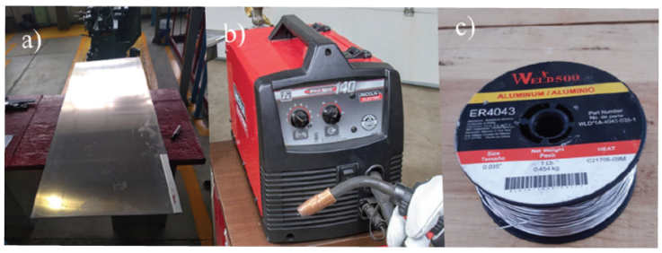
Table 1 Chemical composition of 6063-T6 and ER4043 (wt. %)
| Material | Al | Si | Mg | Cu | Fe | Mn | Zn | Ti | Ni |
|---|---|---|---|---|---|---|---|---|---|
| 6063-T6 | 96.7 | 0.605 | 0.783 | 0.130 | 0.477 | 0.098 | 0.016 | 0.022 | 0.003 |
| ER4043 | 92.9 | 5.600 | 0.050 | 0.300 | 0.700 | 0.050 | 0.100 | 0.020 | 0.001 |
To perform the mechanical characterization of the base metal, the specimens were obtained from a 6063-T6 aluminum alloy sheet whose dimensions are 1800 x 2000 x 3.18 mm. The sheets used to manufacture the welding joints were cut with dimensions of 1800 x 100 x 3.18 mm as shown in Figure 2.
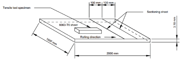
Figure 2 Schematic representation of the sheet used to obtain the tensile test specimens and welding joints
The machining of the AEIM joint was carried out in the sectioning sheet. The MIEA technique refers to the design of the joint which promotes the dilution of the base metal (Al-Si-Mg) with the filler metal (Al-Si), which generates a fusion zone that can be thermally treated by solubilization and artificial aging (-T6). The dimensions for machining can be seen in the Figure 3.
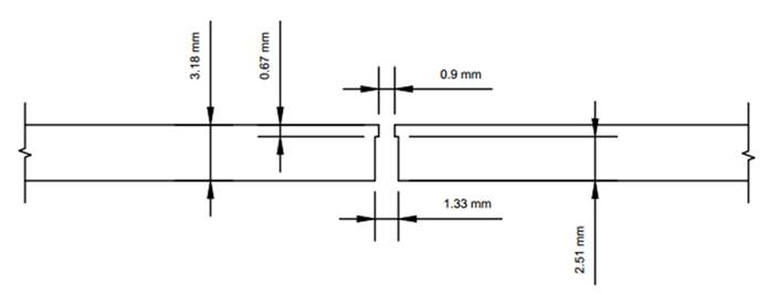
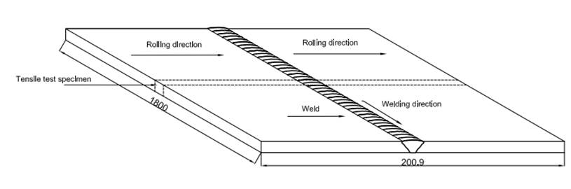
Figure 4 shows the schematic representation of welded joints by MIG process. The section from which the welded joint specimens were obtained for the tensile tests is also observed. The welding parameters used were as follows: electrode feeding at a speed of 145 mm s-1, positive direct current electrode, voltage of 24 V, and current of 120 A. A 100 pct Ar gas shielding was used with a flow rate of 23.6 L min-1 and the travel speed of the heat source was 3.6 mm s-1 (Ambriz et al., 2010b).
Postweld heat treatment (PWHT)
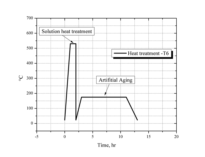
Postweld Heat Treatment (PWHT) of solution and artificial aging and solution was made after the welding process (Figure 5). The heat treatment -T6 has been carried out as follows:
Solution heat treatment. The welded joints were heated to a temperature of 520 °C for one hour, followed by rapid cooling in water to reach 20 °C.
Artificial aging heat treatment: Once the welded joints reached the temperature of 20 °C, the samples were placed in a muffle at a temperature of 175 °C for 8 hours (Handbook, 1991).
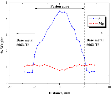
A scanning electron microscope (Quanta 3D FEG) equipped with energy-dispersive X-ray (EDS) detector was used was used to carry out the chemical analysis (weight percent) for Si and Mg of welded joints + PWHT condition. A measurement was made every 500 μm from the center of the weld bead towards the base metal. Each analysis was performed for 50 seconds and the results were plotted as percentage by weight vs. distance from the center of the weld.
Mechanical properties
The specimens for tensile tests have been obtained from the welded sheets and base metal. Design of the test specimens was made according the standard JIS Z 2201: 1998.
Tensile tests were conducted on a hydraulic testing machine UH-30A Shimadzu with 300 kN of load capacity by using a 1.0 mm min-1 crosshead displacement. The increment in length of the reduced section was quantified by strain gauge extensometer of 10 mm length. For the evaluation of the hardness of the base metal, the welded joint and welded joint + PWHT a Vickers Microhardness Meter SMVK-100ZS Metrotec has been used. For the microhardness tests a load of 0.981 N with dewell time of 20 seconds on polished surface has been used. A microhardness scanning has been carried out every 0.5 mm making 200 measurements.
3D and finite element modeling
For the bumper design, the RCAR recommendations have been considered (RCAR Bumper Test, 2010). Among those recommendations is the manufacture of bumpers that have high energy absorption, installed at common heights, protect the vehicle in low speed crashes, reduce damage to the bumper only, stable during impacts and avoid structural damage.
In Zahedan (2020) study, 6063 aluminum profiles of 54 x 34 mm2 with a wall thickness of 2 mm were used. The specimens were manufactured with a length of 500 mm.
Commercial 101 x 51 mm 6063-T6 aluminum profile with a thickness of 3.18 mm was used for simulation analysis. This profile is the one that most closely resembles the conditions of the welding process carried out in aluminum sheet joints, for that reason its mechanical properties have been used to be able to use them in a real structure.
In the graphical environment of ANSYS® LS-DYNA® Workbench™ 19.2, the experimental data of the engineering stress-strain curves of aluminum alloy and 6063-T6 aluminum alloy welded + PWHT have been loaded into the graphic environment. These mechanical properties can be seen in Table 2.
Table 2 Mechanical Properties used in LS-DYNA Workbench™
| General Non-Linear Materials | |||
|---|---|---|---|
| Aluminum 6063-T6 | Aluminum 6063-T6 + PWHT | Structural Steel NL | |
| Density (kg/m3) | 2700 | 2700 | 7850 |
| Young´s Modulus (Pa) | 6.89E10 | 6.87E10 | 2E11 |
| Poisson´s Ratio | 0.33 | 0.33 | 0.3 |
| Bulk Modulus (Pa) | 6.75E10 | 6.73E10 | 1.66E11 |
| Shear Modulus (Pa) | 2.59E10 | 2.58E10 | 7.69E10 |
| Plastic Strain Failure | 0.18 | 0.06 | 0.19 |
The CAD modelling of the bumper and impactor were designed and imported from SolidWorks® (Figure 6a). Some parameters were used for FEM analysis. For example, end time (0.01 sec.), control solid (esort 1), control energy (hgen 2), control bulk viscosity (q1 1.5), control solid (esort 1), control shell (wrpang 20), the mechanical parameters for the impactor (mat. rigid ID 1, ro 2.5E08, E 200000, pr 0.3, section solid ID 2), the mechanical parameters for 6063-T6 welding (mat. rigid ID 2, ro 2.7E09, E 68900, mat. add erotion effeps (0.18), the mechanical parameters for 6063-T6 welding + TTPS (mat. rigid ID 6, ro 2.7E09, E 68700, mat. add erotion effeps 0.06), the bumper and holders were meshed by shell element material type 2 (mat-plastic-kinematic), used in metallic materials. This model is suited to model isotropic and kinematic-hardening plasticity. Also, assuming friction interaction between bumper surfaces and bumper surfaces a control contact parameters were used (islchk 1, shlthk 1). The impactor speed was 4 km/hr (defined in Section 2.7 of the R42 regulation). For the bumper, the material mat024 has been used, whose behavior is linear plasticity and treats elastic deformations using a hyperelastic formulation. The size of each element used in the discretization was 0.005 m.
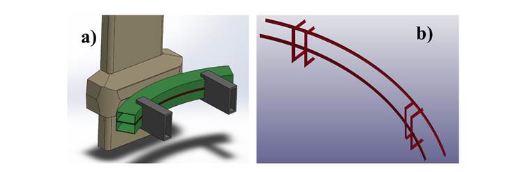
Figure 6 a) Impactor and bumper modelling in SolidWorks®, b) Meshing of welding zones (6063-T6 + AEIM + ER4043 + PWHT)
In the case of meshing the impactor, the mat20 material has been used, which is rigid and non-deformable. The size of each element used in the discretization was 0.009 m.
For the modeling of the real metal structure of the bumper, the mechanical properties of the welded joints of aluminum alloy 6063-T6 + AEIM + ER4043 + PWHT were used, which are: the modulus of elasticity
Results and discussion
Welding
Several experiments were carried out to adjust the parameters that allowed to manufacture welded joints with high quality. Figure 7 shows macrostructural image welding, result of the parameter setting on the Lincoln Pro MIG 140® welding machine applied in 6063-T6 aluminum alloy sheets. Table 3 shows principal welding parameters setting in the MIG welding process. As can be seen, aluminum alloy welding is very difficult to manufacture. For example, a torch high speed and high heat input generates a concentration of stresses that give rise hot cracks at the grain edges (Figure 7b). A torch high speed and low heat input generates lack of penetration and porosity (Figure 7c).
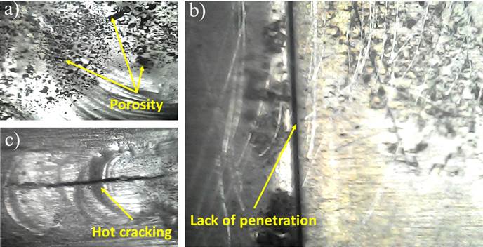
Figure 7 Defects in welding joints generated during the adjustment of welding parameters by MIG technique: a) Porosity, b) Lack of penetration, c) Hot cracking
Table 3 Welding parameter setting
| Current (A) | Voltage (V) | Torch speed (mm s-1) | Thermal efficiency | Heat supply (J mm-1) | Results |
|---|---|---|---|---|---|
| 120 | 24 | 3.6 | 0.95 | 760 | Porosity and good penetration, good quality weld bead |
| 130 | 24 | 4 | 0.95 | 823.33 | Deformation due to excessive heat supply the sheets and hot cracking |
| 115 | 23 | 5 | 0.95 | 502.55 | Porosity and lack of penetration |
| 110 | 22 | 5 | 0.95 | 459.8 | Lack of penetration of weld bead |
| 110 | 24 | 5 | 0.95 | 501.6 | Lack of penetration of weld bead |
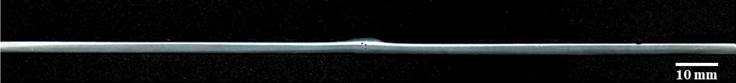
Once the parameters were adjusted in the welding machine eliminating defects like hot cracks and lack of penetration, the aluminum alloy welded joints were manufactured using the best conditions that were: 120 A, 24 V, torch speed of 3.6 mm s-1. Figure 8 shows the macrostructural aluminum joints with high quality. With the MIG welding conditions, good penetration in the weld bead can be observed, no hot cracks were generated, but porosity due to the high diffusion of Hydrogen in the liquid aluminum was observed.
During the welding process the dilution of Al, Si, and Mg was promoted in the fusion zone. Such a chemical composition was produced in the fusion zone (Al-Si-Mg), the fusion zone was hardened by solid solution and artificial aging using a PWHT. An important aspect of the macrostructural profile that explains why the chemical composition (Al-Si-Mg) sensitive to heat treatment -T6 was generated can be explained by considering the areas that make up the 6063-T6 aluminum alloy joint (Figure 9). Through the calculation of these areas it is possible to determinate the percentage of dilution to obtain the correlation that exists between the percentage of dilution and the increase in mechanical properties (Table 4).
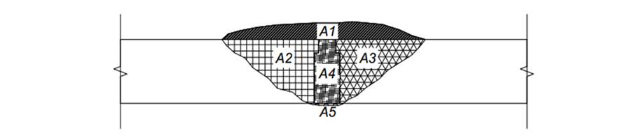
Table 4 Weld profile areas for calculating the percentage of dilution
| Partial section of the welded joint | Area (mm2) |
|---|---|
| A1 (crown) | 6.6696 |
| A2 (fused area of base metal) | 9.0575 |
| A3 (fused area of base metal) | 7.9844 |
| A4 (fused area of base metal + filler metal) | 3.9413 |
| A5 (root) | 0.1473 |
To calculate the percentage of dilution, the original area of the joint preparation, the fused areas on both sides of the base material, as well as the crown and root of the weld were considered by means of the following expression:
As can be seen, the dilution percentage is high (61.3 %), this means that a high proportion of Si atoms are added in the molten zone by the filler material (ER4043) and are combined with Mg atoms from the base material. This combination favors the generation of intermetallic, and therefore it is possible to harden the fusion zone by solid solution and artificial aging.
The composition in the fusion zone of the welded joint is presented in Figure 10. It displays the Si and Mg concentration profile as a function of distance by the energy-dispersive X-ray spectroscopy (EDS) technique. Using Scanning Electron Microscopy (EDS), a semi-quantitative elemental analysis was made to determine the percentage by weight present in the base metal and the fusion zone. The concentration of Si remains constant and rises as it approaches the center of the joint. On the other hand, the Mg concentration remains constant and decreases as the center of the joint approaches. This is because the filler metal does not contain Mg, that is, the Mg comes from the base metal. By having a larger area of fusion zone, the concentration of Mg decreases due to the fact that it must occupy a larger area than the initial area, however the Mg deficit is compensated by Si, increasing the concentration in the fusion zone. With heat treatment, Si and Mg atoms tend to diffuse to try to eliminate differences in concentration and produce a homogeneous composition in the fusion zone.
Mechanical properties
To compare the mechanical properties after welding, 3 conditions were analyzed:
a) base metal, b) welding joint by MIEA + MIG + PWHT. For each condition, 5 specimens were manufactured, giving a total of 15 specimens. The tensile test results shown are the average results of the 5 tests for each condition. The specimens for the stress tests in condition b) joint welded by MIG + MIEA and c) joint welded by MIG + MIEA + PWHT.
Figure 11 shows at a macro level the fracture zone of a test piece tested under tension in joint welded by MIG + MIEA + PWHT condition. Also Figure 11 shows the fracture zone where the pores generated during the welding process. This porosity decreases the cross-sectional area, therefore less energy is needed to break the specimen.
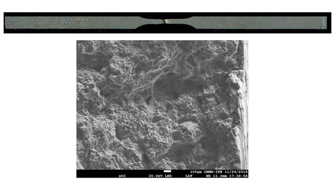
Figure 12 shows the stress-strain curves of the base material, welded joints, and welded joint plus PWHT. In the three conditions, an elastic modulus - 68 MPa was obtained. The yield stress and the tensile stress decreased more than 40 pct concerning the base metal 6063-T6 due to the over-aging during the welding process. In the other hand, the elongation capacity was above 20 pct caused by the thermal cycle. The latter changed the microstructure of the material which evidenced by the sequence of microstructural transformation (Prapas et al., 2017; Elangovan & Balasubramanian, 2008).
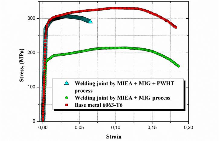
It is worth mentioning that he welding process is a process of degradation of mechanical properties due to temperatures ranging from 220 °C to 380 °C are reached, as a result, the HAZ is an overaged area. In temperature range mentioned above, intermetallic
With the PWHT process, mechanical properties were recovered, for example, the yield strength increases to 270 MPa with respect to the yield strength after the welding process (170 MPa). This represents 59 pct and is attributed to the dilution of the base material containing Al-Si-Mg with the filler metal containing Al-Si in the fusion zone (Table 5).
Table 5 Tensile mechanical properties
| Material | Modulus of Elasticity (GPa) | Yield Strength (MPa) | Tensile Strength (MPa) | Elongation at Break (pct) | Energy to failure (MJ m-3) |
|---|---|---|---|---|---|
| 6063-T6 | 68.9 | 270 | 330 | 18 | 57.01 |
| Welding joint + MIEA+ MIG | 68.7 | 170 | 214 | 18 | 37.12 |
| Welding joint + MIEA+ MIG + PWHT | 68.7 | 270 | 304 | 6 | 18.81 |
Figure 13 shows a microhardness scan in weld condition and a microhardness mapping in weld condition. Here you can see three regions with different levels of hardness, and they are: Fusion zone, Metal base zone and Heat affected Zone (HAZ).
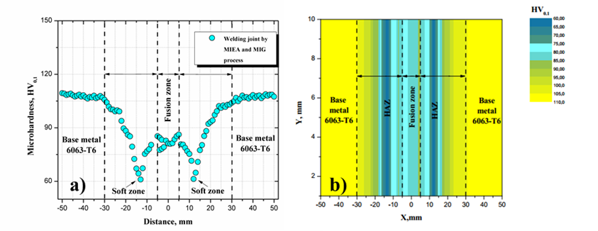
Figure 13 a) Microhardness scan and b) Microhardness mapping of welding joint by MIEA and MIG process
The Fusion zone promoted by dilution between the base metal (Al-Si-Mg) and the filler metal (Al-Si) has approximately 10 mm. HAZ section is produced by a microstructural transformation of precipitates of precipitates
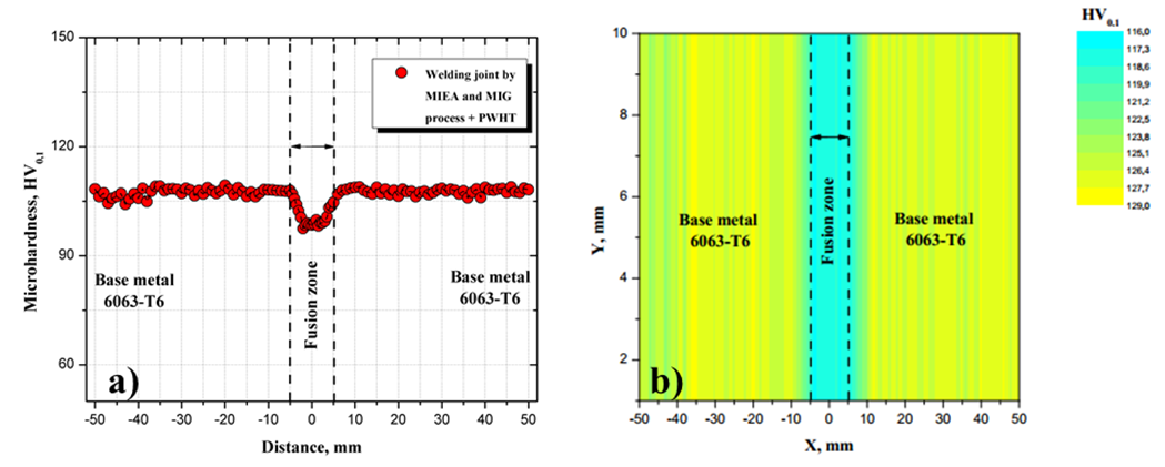
Figure 14 a) Microhardness scan and b) Microhardness mapping of welding joint by MIEA and MIG + PWHT process
Since post-weld heat treatment is a reversible process (Prapas et al., 2017; Elangovan & Balasubramanian, 2008), it was applied to recover the mechanical properties which were lost in the welding process. Figure 14a shows a microhardness increase from 60 HV0.1 to 110 HV0.1 where was the HAZ. With this procedure the HAZ recovers the mechanical properties of 6063-T6 aluminum alloy. With this, the welded joint has only two important zones which are the base metal zone and the fusion zone. In addition, it was also observed that each of these zones has its own mechanical properties and different from each other.
Numerical simulation
The simulation of low-speed impact has had a duration of 74.99
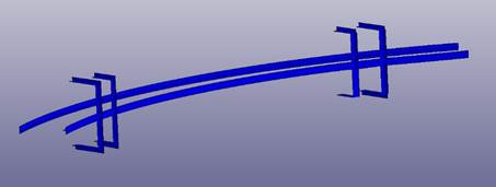
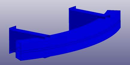
Figure 15 shows the model of 6063-T6 + MIEA + MIG / MAG + PWHT aluminum welded zones. These areas are part of the bumper structure shown in Figure 16.
In order to make an approximation of the model that makes possible to relate the force absorbed by the bumper as a function of displacement, a linear regression has been carried out. With this linear regression the following mathematical model has been obtained:
From the slope obtained in the linear regression (Figure 17), it is possible to determine the relationship between the increase in force and the displacement of the bumper due to the force applied to the structure, that is, the total work exerted on the structure. The total work
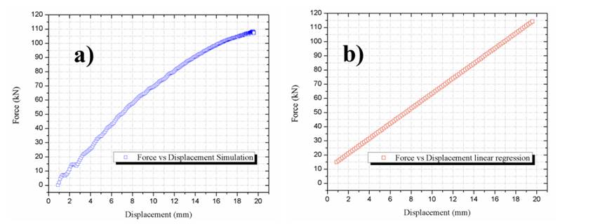
Figure 17 a) Force vs Displacement (work exerted on the bumper) and b) Force vs Displacement (linear regression)
Figure 18 shows the displacement generated when the impactor hits the bumper perpendicularly at a speed of 4
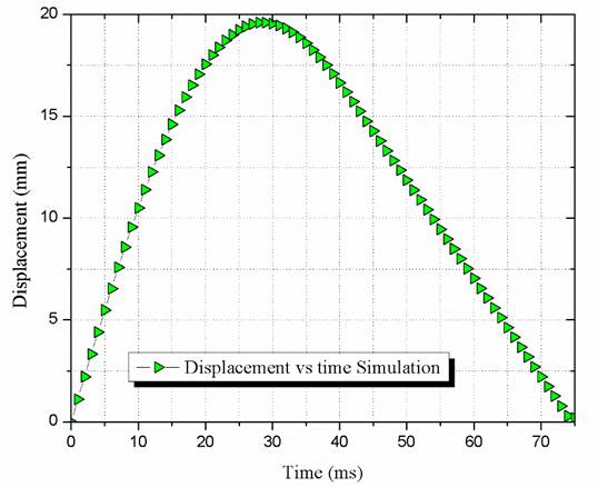
The maximum displacement is generated is 19.59
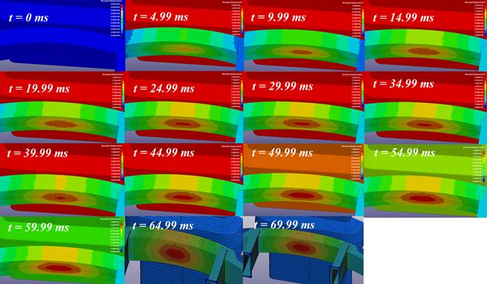
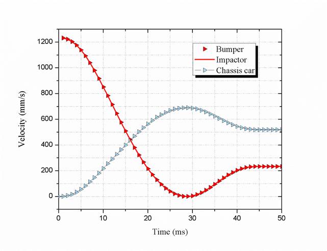
During impact there is a conservation of linear momentum, that is, all linear momentum is transferred to the bumper. During the collision, the kinetic energy is not conserved since part of this energy is transformed into internal elastic potential energy when there are permanent deformations in the collision. It should be mentioned that the welded joints plus the PWHT show good mechanical resistance, that is, permanent deformations have been generated, however, these deformations are small due to the increase in mechanical resistance obtained with the post-welding heat treatment (Figure 20).
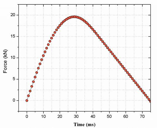
An important factor is the analysis of the evolution of the force (Figure 21). In this case, the simulation shows a maximum impact force value of 19.59 kN. Structurally, the force with which it is impacted does not generate severe deformations, that is, the mechanical integrity of the structure has sufficient stiffness to absorb the impact without causing severe damage.
The stress analysis has also been carried out; among the main results it has been possible to observe stress levels that in the bumper ranging from 289.2 to 330.2 MPa. Figure 22 shows the evolution of the Von Mises stress whose maximum point is at a time of 29.99 ms with a value of 330.2 MPa in the front part of the bumper. It has also been observed that the impact has been able to deform the bumper plastically, however, said deformations are not severe, it can be concluded that the impact has not affected the mechanical integrity of the structure.
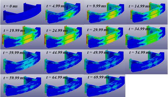
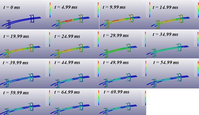
Figure 23 shows the evolution of Von Mises stresses in the welded joints, the material can absorb energy in the form of elastic and plastic deformation, at the end of the impact process it can be seen that there are minimal permanent deformations in the joints When welded, these deformations are located in the center of the bumper, in addition, in the simulation no deformations were generated that could compromise the mechanical integrity of the bumper.
Conclusions
The design of the bumper of this study has included the mechanical characterization of 6063-T6 aluminum welded joints by the AEIM + MIG / MAG process + PWHT technique, all the techniques used previously allow to recover the mechanical properties that are lost during the welding process. The mechanical properties of the 6XXX series aluminum alloy joints decrease due to the thermal heating cycle of the welding process. The post-weld heat treatment eliminated the over-aging of the HAZ section and increased the mechanical resistance in the fusion zone. Favorable chemical composition in the fusion zone was obtained with the heat treatment in the alloy (Al-Si-Mg) due to MIEA joint helped to dilute the filler metal and the base metal.
However, there are some limitations such as porosity and low ductility, the low ductility that is recovered is also due to heat treatment. Despite this, the increase in mechanical resistance provides important advantages in this study. First, in order to carry out the numerical simulation, the mechanical properties of the base material and the mechanical properties of the weld have been used to form a solid structure.
For simulation purposes, it has been considered that the maximum stress that the bumper must withstand must be less than the limit of proportionality (yield stress). In this case, the Von Mises stress slightly exceeds the yield stress, which is why small permanent deformations are generated in the fusion zone of the bumper.
Finally, the optimization process can be carried out in the bumper design. Frame geometry can be redesigned, which may increase the weight of the frame a bit but can provide greater impact stiffness. Another important improvement is to add an energy absorber made from a resistant polymeric material that can act as a fuse, that is, absorb the initial impact energy to avoid that the total energy can go directly to the bumper. Regarding the material and the manufacturing process, a simulation is suggested by increasing the thickness of the sheet or tubular profile used to manufacture the bumper. Increasing the size of the geometric sections would reduce the impact effect, that is, cause only elastic deformations with the conditions used in this study.

