SciELO - Scientific Electronic Library Online

 
vol.23 issue1Characteristics and calibration of the mexican boundary layer wind tunnel at UNAM author indexsubject indexsearch form
Home Pagealphabetic serial listing  

Services on Demand

Journal

Article

Indicators

Related links

  • Have no similar articlesSimilars in SciELO

Share


Ingeniería, investigación y tecnología

On-line version ISSN 2594-0732Print version ISSN 1405-7743

Ing. invest. y tecnol. vol.23 n.1 Ciudad de México Jan./Mar. 2022  Epub May 02, 2022

https://doi.org/10.22201/fi.25940732e.2022.23.1.008 

Artículos

Bidirectional EV charger with ancillary power quality capabilities

Cargador bidireccional de VE con capacidades auxiliares de calidad de la energía

1Tecnológico Nacional de México Instituto Tecnológico de La Laguna División de Estudios de Posgrado e Investigación Torreón, Coahuila, México. E-mail: jorge_lara_c@yahoo.com

2Tecnológico Nacional de México Instituto Tecnológico de La Laguna División de Estudios de Posgrado e Investigación Torreón, Coahuila, México. E-mail: coni.hernandez@ieee.org

3Tecnológico Nacional de México Instituto Tecnológico de La Laguna División de Estudios de Posgrado e Investigación Torreón, Coahuila, México. E-mail: marjona@ieee.org

4University of the Witwatersrand School of Electrical and Information Engineering Johannesburg, Gauteng, South Africa. E-mail: lesedi.masisi@wits.ac.za

5École de Technologie Supérieure Department of Electrical Engineering Montreal, Quebec, Canada. E-mail: ambrish.chandra@etsmtl.ca


Abstract

This paper presents a bidirectional electric vehicle (EV) charger with ancillary power quality (PQ) capabilities in grid-to-vehicle (G2V), vehicle-to-grid (V2G) and vehicle-to-home (V2H) applications. The proposed configuration consists of a five-level (5L) neutral point clamped (NPC) converter in cascade with a dual-active half-bridge (DAHB) DC-DC converter. The proposed cascaded control strategy used for regulating the common DC bus voltage as well as for compensating the grid current harmonics and the reactive power through the 5L-converter is based on a performant proportional-resonant (PR) compensator. By applying the single-phase-shift (SPS) technique to the DAHB converter, the battery power flow is accurately regulated. A detailed study with exhaustive tests and simulation results obtained in MATLAB-SimPowerSystems for a full-scale power system based on a Nissan Leaf´s battery validate the fairly good performance of the proposed configuration and control strategies. The main achievements of this work are: 1) the system’s stability is maintained even during fairly abrupt changing conditions, 2) in the steady-state of the G2V/V2G operation modes, the total harmonic distortion (THD) of the grid current remains below 3 % while the power factor (PF) is kept at unity, 3) the reactive power demanded from the grid is zero despite of feeding a highly nonlinear load, and 4) when a power outage occurs, the transition to the V2H mode is seamless and the home load is uninterruptedly supplied with a very low-distortion output voltage from the 5L-converter.

Keywords: Electric vehicle; EV charger; multilevel converter; G2V/V2G/V2H; active filter; power quality; resonant controller

Resumen

Este artículo presenta un cargador bidireccional de vehículos eléctricos (VE) con capacidades auxiliares de calidad de la energía (CE) en aplicaciones de red-a-vehículo (RaV), vehículo-a-red (VaR) y vehículo-a-hogar (VaH). La configuración propuesta consiste en un convertidor de conexión al punto neutro (CPN) de cinco niveles (5N) en cascada con un convertidor CD-CD dual-activo de medio-puente (DAMP). La estrategia propuesta de control en cascada utilizada para regular el voltaje del bus común de CD, así como para compensar los armónicos de corriente de la red y la potencia reactiva mediante el convertidor de 5N está basada en un compensador proporcional-resonante (PR) de alto rendimiento. Aplicando la técnica de desplazamiento simple de fase (DSF) al convertidor DAMP, el flujo de energía de la batería es regulado con precisión. Un estudio detallado con pruebas exhaustivas y resultados de simulación obtenidos en MATLAB-SimPowerSystems para un sistema de potencia a escala completa basado en una batería del Nissan Leaf validan el bastante buen desempeño de la configuración y las estrategias de control propuestas. Los principales logros de este trabajo son: 1) la estabilidad del sistema es mantenida incluso durante condiciones cambiantes bastante abruptas, 2) en estado estable de los modos de operación RaV/VaR, la distorsión armónica total (DAT) de la corriente de la red permanece por debajo de 3 % mientras que el factor de potencia (FP) es conservado en la unidad, 3) la potencia reactiva demandada de la red es cero a pesar de alimentar una carga altamente no lineal, y 4) cuando ocurre un corte de energía, la transición al modo VaH es ideal y la carga doméstica es ininterrumpidamente alimentada con un voltaje de muy baja distorsión proveniente de la de la salida del convertidor de 5N.

Descriptores: Vehículo eléctrico; cargador de VE; convertidor multinivel; RaV/VaR/VaH; filtro activo; calidad de la energía; controlador resonante

Introduction

Due to the continuous and unstoppable rising of oil prices and with the aim of contributing to reduce the global greenhouse gas emissions from combustion engines-based cars, the transportation sector is fastly migrating to electric motor-based-vehicles that use as fuel the electricity coming from a battery energy storage system (BESS) (Khan et al., 2018). Bearing in mind the existent 7 million battery EVs worldwide and the forecasting that by 2030, 86 % of the light-vehicle sales will be electric, thus a much more significant penetration of these EVs is expected (Falahi et al., 2013). Given that the EV batteries are charged from the grid, this massive increase of electric vehicles alike represents a heavy load connected to the power system, thus negatively impacting on power quality aspects, e.g., injecting harmonics into the utility, rising the neutral current, drawing excessive reactive power as well as causing disturbances and instabilities (Jiang et al., 2014).

The SAE J1772 standard defines two charging levels for on-board EV chargers. The AC level 1 is a single-phase system at 120 Vrms with a maximum power of 1.92 kW whereas the AC level 2 is a split-phase or single-phase three-wire system at 240 Vrms with a maximum power of 19.2 kW. Bearing in mind that these two levels are suitable for home integration, the basic on-board and unidirectional EV charger initially designed for the single purpose of working in the G2V mode can be used as a multifunctional bidirectional power converter that also operates in the V2G and V2H modes (Kwon & Choi, 2017). Therefore, the added features to the elemental EV charger include the grid support, the compensation of the nonlinear current drawn by the home appliances as well as the implementation of an uninterruptible power supply (UPS) system that takes advantage of the EV batteries’s energy for supplying the home electricity during a power outage (Monteiro et al., 2016). It is important to note that the inclusion of these ancillary power quality capabilities to the EV charger must consider the requirements of SAE J2894.

Over the last years, several EV charger topologies have been devised (Yilmaz & Krein, 2013). The dual active full bridge (DAFB) and the DAHB topologies have the outstanding advantage of including a high-frequency (HF) transformer that provides galvanic isolation. This property is particularly very attractive in EV applications for safely interconnecting the EV batteries to the grid and the home appliances, thus contributing to comply with international standards such as the IEC 61851. The DAHB topology has the advantages of requiring a simple control strategy, reaching a high efficiency and comprising very few switching devices what represents a lower cost and a smaller size (He & Khaligh, 2017). For electrically linking this DAHB DC-DC converter to the point-of-common coupling (PCC), a multilevel converter (MLC) place in between is commonly chosen rather than converters based on two-level topologies because the former features a reduced stress of the switching devices, a smaller sizing of the required passive filter and a lower THD of the output voltage (Choudhury et al., 2021). Furthermore, this better voltage waveform is achieved by switching the converter at lower frequencies what is equivalent to less switching losses and consequently to a higher efficiency. As the number of levels increases, the performance of the converter improves but at the expense of a higher components count, a bigger failure probability and a more complex control strategy (A & Sivakumar, 2015). For active filtering applications, the five-level converter is a good candidate with an optimum trade-off among the afore-mentioned factors. The 5L-converter analyzed in this paper is based on a simplified NPC topology that consists of only six switches, two clamping diodes and two splitting capacitors (Haddad et al., 2015). This configuration has been selected over the following topologies: flying capacitor (Choudhury et al., 2021), cascaded H-bridge (CHB) (Sumithira & Nirmal, 2013), NPC full-bridge (Xu et al., 2014) and ANPC (Wang et al., 2017), because it requires fewer switching devices, all the voltages are derived from only one isolated DC source, can operate at low switching frequencies and does not need a precharge of the capacitors at startup.

In the present paper, the authors study the performance of a single-phase bidirectional EV charger with ancillary power quality capabilities in V2G, G2V and V2H operation modes. The proposed EV charger configuration is composed of a 5L NPC converter connected in series with a DAHB DC-DC converter. It is important to highlight that this charger topology has not been previously proposed nor analyzed in the past literature. Another contribution of this work is the proposal of a cascaded control strategy based on a performant proportional-resonant compensator for regulating the common DC bus voltage as well as for compensating the grid current harmonics and the reactive power through the 5L-converter. In contrast, a classical single-phase-shift technique is used for controlling the battery power flow through the DAHB converter.

This paper is organized as follows: the second section describes the single-phase 5L bidirectional converter. The DAHB DC-DC converter is analyzed in the third section. The fourth section includes the design of the LCL passive filter and provides the characteristics of the Nissan Leaf’s Lithium-Ion EV battery. The fifth section presents the simulation results obtained in MATLAB - SimPowerSystems for an exhaustive set of tests and conditions in the three operation modes: G2V, V2G and V2H. Finally, the conclusion and some important remarks are given in the last section.

Single-phase five-level bidirectional converter

Zone D of Figure 1 shows the topology of the single-phase 5L bidirectional converter used for regulating the energy transfer and improving the power quality on the grid side. Note that these PQ ancillary capabilities carried out by the shunt active filter are available only when the grid is connected to the system, i.e., in the G2V/V2G modes. When a power outage occurs, the V2H mode is activated and the 5L-converter only works as a conventional voltage inverter. However, even under this operating condition, in comparison with two- and three- level converters, this 5L-converter provides a better output voltage characterized by a lower harmonic content (Vahedi et al., 2016).

Figure 1 Overall electric circuit of the bidirectional EV charger with ancillary power quality capabilities in G2V, V2G and V2H operation modes 

The topology of the 5L-converter studied in this paper is composed of one arm of a two-level inverter and one arm of a three-level diode NPC inverter. The resulting converter consists of six switches, two clamping diodes and two splitting capacitors (Haddad et al., 2015). The switching states  SSK   and the output voltages Vf for this 5L-converter are given in Table 1.

Table 1 Switching states and output voltages of the 5L-converter 

Switching State (SSk) State of Switches Output
Voltage (Vf)
S1 = S2 S3 = S4 S5 = S6
1 0 1 1 + Vdc
2 0 0 1 + Vdc/2
3 0 0 0 0
4 1 0 1 - Vdc/2
5 1 0 0 - Vdc

Figure 2 shows the proposed cascaded control strategy used for regulating the common DC bus voltage Vdc as well as for filtering out the grid current harmonics and compensating the reactive power. The functioning of this strategy is explained as follows. First, the low-pass filtered (LPF) measurement of Vdc is subtracted from the DC bus voltage reference Vdc * and the resulting difference goes to a PI controller. The grid current reference ig * is obtained by multiplying the output from this controller times a unitary sinusoidal signal in-phase with the grid voltage Vg. This synchronization is carried out by means of a phase-locked- loop (PLL). Afterwards, the difference between the desired grid current ig * and the measured value ig becomes the input error to a PR controller tunned for the first twenty-one grid harmonics. The bode plot of the resulting transfer functions is shown in Figure 3. It is important to remark that unlike PI controllers which have a limited bandwidth and only properly track constant input errors, the PR controllers are capable of tracking sinusoidal signal errors due to their theoretical infinite gain at the resonance frequency (Teodorescu et al., 2006). For this reason, PR and no PI compensators have been used for filtering out the grid current harmonics which have a frequency that is an integer multiple of the fundamental 60 Hz signal. According to the cascaded control strategy, the output from the PR block is then subtracted from the grid voltage for obtaining the reference Vf * of the voltage to be generated by the 5L-converter. Note that there is a selector for choosing the input signal to the multicarrier PWM phase-disposition (PD) block. It can come from the V2G/G2V mode or well from the V2H mode where the virtual PLL provides a sinusoidal reference of 60 Hz and 340  Vpk. Finally, the state of the six switching signals from S1 to S6 are obtained by applying the PWM PD method (Lara et al., 2021a).

Figure 2 Cascaded control strategy for the 5L-converter based on PI and PR controllers and the Multicarrier PWM-PD modulation 

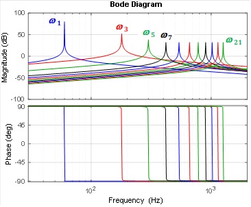
Figure 3 Bode plot of the twenty-one transfer functions included in the PR controller block of Figure 2  

The analysis of the cascaded control strategy represented in Figure 2 is described below. First of all, it is necessary to remark that this modeling is based on the assumption that the high-frequency (HF) current harmonics are fully attenuated and ideally absorbed by the low impedance path that they found through the capacitor Cf of the LCL passive filter shown in Zone C of Figure 1. Therefore, the low-frequency (LF) current harmonics flowing in Lf and Lg are the same. Bearing in mind that the magnitude of the attenuated HF current components is negligeable in comparison with the unfiltered LF ones, thus the following equations represent a valid approximation for accurately modeling the significant low-frequency behaviour of the filter which contributes the most. By applying the Kirchhoff's voltage law (KVL) to the resulting simplified L filter, the following expression is derived:

Lf+Lg[digt]dt+Vft-Vgt=0 (1)

After applying the Laplace transform to (1) and considering the small-signal modeling, the grid current is given by:

igs=[Vgs-  Vdc(s)][(Lf+Lg) s] (2)

where δ is the duty cycle of the converter. Bearing in mind that the outer voltage loop is much slower than the inner current loop, its transfer function is simplified as:

His=1(Lf+Lg) s (3)

By applying the Kirchhoff's current law (KCL) at the node N located within zone D of Figure 1, the following equations are obtained:

C d[Vdct]dt+ift-ibust=0 (4)

if(t)=[Vft-Vgt][g·(Lf+Lg)] (5)

where C is half the value of the capacitances Caf1=Caf2 and g represents the grid angular frequency. After substituting (5) into (4) and considering the small-signal modeling, the transfer function of the outer voltage loop is derived as:

HVs= [g·(Lf+Lg) ] [g·(Lf+Lg) C s+] (6)

The gains of the respective PI and PR controllers have been found by observing the cascaded closed-loop response of the transfer functions (3) and (6) in MATLAB-SimPowerSystems (Vahedi et al., 2016; Lara et al., 2021b).

Dual active half-bridge DC-DC converter

As it can be seen in zone E of Figure 1, the EV battery is connected to the 5L-converter through a DAHB DC-DC converter with boost and buck voltage capabilities, thus increasing and decreasing the voltage at either of its sides as required. This converter is composed of one leg of two switches and one leg of two capacitors at each side of the HF transformer located between both bridges. Such transformer not only has galvanic isolation properties but also allows reducing the weight and volume of the converter by increasing its operating frequency. Due to these characteristics, both the DAFB and the DAHB configurations have become very attractive for EV applications.

Given that in the DAFB topology two couple of switches replace two legs of split-capacitors in the DAHB configuration, in consequence, the former is more costly, bulky and complex. Furthermore, the unique four switches of the DAHB converter also experience a lower stress since only half of the DC bus voltage is applied to them. By considering this feature, if the same HF transformer were used in both topologies and operated at the same switching frequency, the one working with the DAHB would present a lower flux swing, equivalent to smaller core losses and consequently such converter would achieve a higher overall efficiency. Because of the presence of the split-capacitors, in the steady-state the DC component is absent in the magnetizing current of the HF transformer, thus alike contributing not only to reduce the core losses but to avoid the saturation phenomenon. All these advantages override the inconvenient of the DAHB topology of being limited to implement only the SPS strategy, where the regulation of the power flow magnitude and direction is done by simply shifting the relative angle between the square voltage signals applied on the terminals of the HF transformer. Table 2 shows the design and operating parameters of the DAHB converter and the HF transformer used to obtain the simulation results included in the fifth section. The control block diagram of the DAHB DC-DC converter is shown in Figure 4. In the V2G operation mode, the power  Pb *   transferred from the EV battery to the grid and the home load is regulated by controlling only the battery current. In contrast, during the G2V mode, the battery may also be charged by controlling its voltage. Hence, by means of selector 1, the classical constant current (CC) - constant voltage (CV) battery charging strategy is straightforwardly implemented.

Figure 4 Control block diagram of the DAHB DC-DC converter based on PI compensators and the SPS technique 

Under the three modes of operation, the switching signals G1 and G2= G-1 as well as G3 and  G4= G-3 are obtained by comparing a triangular carrier of 50 kHz against zero, thus on both sides of the HF transformer there are square waves with the same frequency and a 50 % duty-cycle. By adjusting the relative phase between them, the transfer of energy is accurately controlled. It is interesting to remark that in the V2H mode, the DC bus voltage Vdc is regulated by the DAHB converter with the SPS strategy whereas in the V2G and G2V modes, it is regulated through the 5L-converter applying the cascaded control strategy.

LCL filter design and EV battery characteristics

Single-phase lcl passive filter

The electric diagram of the single-phase LCL passive filter used for attenuating the high-frequency current harmonics generated in the G2V/V2G operation modes and those of voltage in the V2H mode is shown in zone C of Figure 1. By applying the KVL to the two circuit networks of this LCL filter, the following couple of equations in the Laplace domain are derived:

- Vf(s)+Lf s if(s)+  [Rf+1(Cf s)] ifs-igs=0 (7)

Vgs+[Rf+1(Cf s)] igs-ifs+Lg s ig(s)=0 (8)

Solving for ifs in (8) and assuming Vgs=0, the filter current is given by:

ifs=igs Cf Lg s2+Rf Cf s+1[Rf Cf s+1] (9)

By substituting (9) into (7) while considering Vf as the input and ig as the output of the filter, its transfer function HLCL(s) is found as:

HLCLs= igs Vfs= [Rf Cf s+1][Lf Lg Cf s3+ Rf Cf Lf+Lg s2+ Lf+Lg s] (10)

The parameters in (10) have been calculated in accordance with the following design procedure (Reznik et al., 2014; Arab et al., 2020). First, the base impedance Zb and the base capacitance Cb are calculated as:

Zb= Vg2 Pn=240V2[7kW]=8.23 (11)

Cb=1[g Zb]= 1[2   60 Hz 8.23]=322.31F (12)

where  Vg is the rms grid voltage and  Pn the active power from the grid. The value of the capacitor located in the middle branch of the LCL filter is obtained with the following expression:

Cf= Cb=0.05 322.31μF=16.12μF  15μF (13)

where the factor ( represents an adjustment to the base capacitance by assuming a maximum grid power factor variation of 5 %. Note that the capacitance in (13) has been rounded to the nearest commercial value. The grid side inductance Lg is deduced as:

Lg=1k2+1Cf sw2= 10.22+115F  2   10kHz2=101.32H  0.1mH (14)

where k corresponds to the percentage of the desired attenuation and sw means the angular switching frequency of the 5L-converter. The maximum rms current variation Imax is given by:

Imax=  Imax=   Pn Vgrid=0.1 7kW240V=2.92A (15)

where ρ is the allowable current ripple percentage set to 10 %. The converter side inductance Lf is calculated as follows:

Lf=Vdc[6 fsw Imax]= 500V[6 10kHz 2.92A]=2.85mH  3mH (16)

The resonance frequency fres of the LCL filter can be accurately calculated with the following equation:

fres  ( 12)Lf+ LgLf Lg  Cf (17)

after substituting the numerical values of the design parameters, this approximation results in a resonance frequency of about 4.18 kHz, thus properly satisfying the condition:

10fg<fres<fsω/2 (18)

The damping resistance Rf is calculated as:

Rf=1[3 res Cf  ]= 1[3 2   4.18 kHz15F] =0.85  1 (19)

From this design procedure, the parameters of the LCL filter components are finally set as Lf= 3mH, Lg= 0.1mH, Cf= 15F and Rf= 1. By substituting these values in the transfer function (10), the frequency- and phase- response of the designed filter can be found. Figure 5 shows the resulting Bode plot. For comparison purposes, this graph also shows the filter response considering the damping resistances Rf2= 0.1  and Rf3= 10 . It can be observed that the attenuation of the LCL filter with Rf= 1  at fsw/5LC= 10 kHz is about -57 dB.

Figure 5 Bode plot of the LCL filter for three different passive damping resistances: Rf2= 0.1 Ω , Rf= 1 Ω and Rf3= 10 Ω 

Characteristics of the nissan leaf’s lithium-ion ev battery

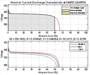
The EV battery used in this study is a Lithium-Ion (Li-Ion) battery manufactured by the automotive energy supply corporation (AESC) for the Nissan Leaf electric vehicles. This Li-Ion battery pack has a rated energy of 24 kWh, a nominal voltage of 360 V and a rated current capacity of approximately 66 Ah (Khan et al., 2018; Maluf et al., 2015). Nevertheless, with the aim of extending the life cycle of the battery pack, the Leaf only uses around 80 % of its capacity. Figure 6 shows the current discharge characteristics of the Nissan Leaf’s battery at the rates of 0.43C, 1C, and 2C, respectively. Note that the term 1C means a discharge current that depletes the entire battery capacity in one hour, thus when drawing continuously a current of 66A during this time, the state-of-charge (SoC) passes from 100 % to 0 %. Although the Nissan Leaf has an on-board battery charger of 3.6 kWh at 16A, it limits the nominal charging rate to only 3.3 kW. These voltage, current and power characteristics of the Nissan Leaf’s battery and charger have been considered in the simulation for properly evaluating the real performance of the proposed system.

Figure 6 Characteristic curves of the Nissan Leaf’s Li-Ion EV battery pack 

Simulation results

In order to study and validate the performance of the proposed bidirectional EV charger with ancillary power quality capabilities, the overall power system shown in Figure 1 has been simulated in MATLAB-SimPowerSystems. Its design and operating parameters are provided in Table 2 of the Appendix. The following three cases have been analyzed: G2V, V2G and V2H.

G2V: Grid-to-vehicle

The first case evaluated is the G2V operation mode, in which the EV battery is charged following the classical CC-CV technique. With the aim of properly validating the overall robustness of the control algorithm, an exhaustive set of tests under different operating conditions has been carried out. The results shown in Figure 7 have been obtained from the following sequence of events:

  • At t= 0, the bidirectional EV charger is turned-on. In order to not surpass the home protection current limit, a smooth starting is achieved by pre-charging the splitting capacitors at an initial voltage of 400 V, and thereafter by following a ramp reference until reaching the full DC bus voltage of 500 V at 0.25 s.

  • At t= 0.5 s, the battery charging current starts being regulated at 4.5A and half a second later, it is increased up to 9A.

  • At t= 1.5 s, the grid voltage is changed from an ideal sinusoidal waveform to a distorted signal with 3rd and 5th harmonics in-phase. The magnitude of these harmonics are 15 % and 5 % of the grid peak voltage, respectively, thereby producing a grid voltage with a total THD of 16 %. This voltage change produces the worst-case scenario for the grid current distortion transient. However, its THD fastly reaches 1% after about 0.25 s.

  • At t= 2 s, the battery charging current is reduced to 4.5A and later at t= 2.5 s, the DC bus voltage is step-changed from 500 V to 450 V.

  • Finally, at t= 3 s, the peak value of the grid voltage is reduced from 340 V to 300 V. However, this variation barely produces a negligible disturbance effect on the system.

Figure 7 Simulation results obtained from an exhaustive test in G2V mode under various operating conditions. A zoom-in of the upper graphs is shown at the bottom 

It is noteworthy how the proposed bidirectional charger remains stable under all the applied disturbances and how in the steady-state: a) the THD of the grid current is always kept below 1.5 %, b) the power factor remains at unity, c) the reactive power supplied by the grid is virtually zero and d) the DC bus voltage is properly controlled at the reference value. Each of the splitting capacitors on the common DC bus has a capacitance of only 1mF. This relatively small value has been enough for keeping the ripple at twice the grid frequency confined to the range of ±10 V. It is important also to remark that the voltage unbalance of such capacitors is kept between ±15 V in all the tests.

During the full simulation, the home load was kept constant. It consumed around 3.08 kW/0.82 kVars before the grid voltage sag at t= 3 s and 2.42kW/0.56kVars after that time. This home load was composed of an RL linear load and two nonlinear loads that in turn were formed by a single-phase full-wave diode-bridge rectifier with an RL load and another one with an RC load. The THD of the total home loads was 16 % before t = 1.5s and 20 % after this time.

V2G: Vehicle-to-grid

The second case evaluated is the V2G operation mode. The results shown in Figure 8 have been obtained from the following sequence of events:

  • At t= 0.5 s, the EV battery current reference ib* is set to -4.5A. Given that the voltage of the battery is around 380 V, thus it delivers a power of approximately 1.7 kW. In this case of study, the home load consumes around 1.6 kVA, therefore, under this condition the load is totally supplied by the EV battery. Hence, during the interval 0.5s-1s, the grid current is zero, as it can be seen in the zoomed-in graph A of Figure 8. The missing 100 W belong to the conduction and switching losses of the power devices.

  • At t= 1 s, ib* is set to -9A so that the EV battery delivers 3.4 kW. This power nearly matches the maximum capacity of the Nissan Leaf’s on-board battery charger. Given that the home load only consumes half of this power, the surplus is sent to the grid. Under this condition, the grid current and grid voltage are out-of-phase, as it can also be noted in the zoomed-in graph B of Figure 8.

  • At t= 1.5 s, the grid voltage is changed from an ideal sinusoidal waveform to a distorted signal with 3rd and 5th harmonics out-of-phase. The magnitude of these harmonics are -15 % and -5 % of the grid peak voltage, respectively. Thus, the distortion of the grid voltage reaches a THD of 16 %.

  • At t= 2 s, by opening the relays 2 and 3 from Figure 1, the RL linear load and the diode-bridge with RC load are disconnected, thus only remaining connected the diode-bridge with RL load.

  • At t= 2.5 s, the DC bus voltage is step-changed from 500 V to 550 V.

  • Finally, at t= 3 s, the peak value of the grid voltage is increased from 300 V to 340 V.

Figure 8 Simulation results obtained from an exhaustive test in V2G mode under various operating conditions. A zoom-in of the upper graphs is shown at the bottom 

As in the steady-state G2V results, also in the V2G mode, the power factor remains at unity, the reactive power on the grid side is zero and the DC bus voltage is efficiently regulated. The applied disturbances produced a maximum overshoot of the DC bus below 25 V. It can also be observed how the capacitors voltage unbalance is confined to ±10 V. During the full simulation, the THD of the home load remained at 15 %, except between the interval 1.5 s-2 s in which the THD reached 22 %. Even in the worst-case scenario, the THD of the grid current was notably kept below 3 %.

V2H: Vehicle-to-home

The third case evaluated is the standalone V2H operation mode where the grid is totally disconnected from the power electronics system. The results shown in Figure 9 have been obtained from the following sequence of events.

Figure 9 Simulation results obtained from an exhaustive test in V2H mode under various operating conditions. A zoom-in of the upper graphs is shown at the bottom 

  • In the first 1.5 s, the relays 4 and 5 from Figure 1 remain open. During this time, the 5L-converter only works as an active filter by keeping the grid current a pure sinusoidal wave and the reactive power on the grid side at zero.

  • At t= 0.5 s, the home load is step-changed from 3.08 kW/0.93 kVars to 2.06 kW/0.43 kVars, and later at t= 2.5 s, it goes back again to the initial value.

  • At t= 1 s, the peak value of the grid voltage is reduced from 340 V to 300 V.

  • Later on, at t= 1.5 s, the relays 4 and 5 are closed and the EV starts charging (G2V mode) by absorbing 1.8 kW from the grid.

  • At t= 2 s, by opening the relay 1 a power-cut happens, and thus the bidirectional EV charger immediately starts supplying the power to the home load (V2H mode) with a sinusoidal voltage very close to the one provided by an ideal grid. Actually, during this islanding mode, the output voltage from the 5L-converter has a THD of only 1.7 %. In the zoomed-in graphs of Figure 9, it can be observed the following at t= 2s:

    1. The ripple at 120 Hz reduces to less than 4Vpk-pk.

    2. The supplying voltage changes from the previous distorted grid signal containing -15 % of 3rd harmonic and -5 % of 5th harmonic with a total THD of 16 % to the high-quality sinusoidal waveform provided by the 5L-converter.

    3. The grid current is zero and the active filter current becomes the load current.

  • Finally, at t= 3 s, the DC bus voltage is step-changed from 500 V to 450 V. It is noteworthy the much faster response of the DC bus voltage regulation in the V2H mode than in the G2V/V2G modes. This is because in the V2H mode, the DAHB DC-DC converter controls the DC bus voltage through the SPS strategy and it has a much wider bandwidth than the cascaded control strategy applied to the 5L-converter that regulates the DC bus voltage in the other two modes of operation.

Conclusions

A bidirectional EV charger with ancillary power quality capabilities in G2V, V2G and V2H applications has been presented in this paper. The proposed cascaded control strategy based on PI and PR compensators has proved its effectiveness by keeping the stability and good performance of the single-phase 5L-converter and the DAHB DC-DC converter despite of all the applied disturbances. The MATLAB-SimPowerSystems- based simulation results obtained from exhaustive tests under various operating conditions have shown that in the steady-state, the G2V/V2G modes of operation allow reaching a very low THD of the grid current, a unit power factor and a zero reactive power on the grid side, thus validating the power converters and their control techniques. It has been also demonstrated how during a blackout the proposed EV charger configuration takes advantage of the energy stored in the Nissan Leaf’s Li-Ion batteries for providing reliable and high-quality home electricity.

Acknowledgments

Authors want to thank the financial support provided by the National Council of Science and Technology of Mexico (CONACYT) through its "Postdoctoral Fellowship Program" under grants 2019-000006-01NACV-00062 and 2020-000022-01NACV-00108.

References

A, M. R., & Sivakumar, K. (2015). A fault-tolerant single-phase five-level inverter for grid-independent PV systems. IEEE Transactions on Industrial Electronics, 62(12), 7569-7577. https://doi.org/10.1109/tie.2015.2455523 [ Links ]

Arab, N., Vahedi, H., & Al-Haddad, K. (2020). LQR control of single-phase grid-tied puc5 inverter with LCL filter. IEEE Transactions on Industrial Electronics , 67(1), 297-307. https://doi.org/10.1109/tie.2019.2897544 [ Links ]

Choudhury, S., Bajaj, M., Dash, T., Kamel, S., & Jurado, F. (2021). Multilevel Inverter: A survey on classical and advanced topologies, control schemes, applications to power system and future prospects. Energies, 14(18), 5773. https://doi.org/10.3390/en14185773 [ Links ]

Falahi, M., Chou, H., Ehsani, M., Xie, L., & Butler-Purry, K. L. (2013). Potential power quality benefits of electric vehicles. IEEE Transactions on Sustainable Energy, 4(4), 1-8. https://doi.org/10.1109/tste.2013.2263848 [ Links ]

Haddad, M., Rahmani, S., Hamadi, A., & Al-Haddad, K. Improving power quality using a new single phase multilevel Active Power Filter. IECON 2015 - 41st Annual Conference of the IEEE Industrial Electronics Society. 2015, pp. 771-776. https://doi.org/10.1109/iecon.2015.7392192 [ Links ]

He, P., & Khaligh, A. (2017). Comprehensive analyses and comparison of 1 kW isolated DC-DC converters for bidirectional EV charging systems. IEEE Transactions on Transportation Electrification, 3(1), 147-156. https://doi.org/10.1109/tte.2016.2630927 [ Links ]

Jiang, C., Torquato, R., Salles, D., & Xu, W. (2014). Method to assess the power-quality impact of plug-in electric vehicles. IEEE Transactions on Power Delivery, 29(2), 958-965. https://doi.org/10.1109/tpwrd.2013.2283598 [ Links ]

Khan, S., Mehmood, K., Haider, Z., Bukhari, S., Lee, S.-J., Rafique, M., & Kim, C.-H. (2018). Energy Management Scheme for an EV smart charger V2G/G2V application with an EV power allocation technique and voltage regulation. Applied Sciences, 8(4), 648. https://doi.org/10.3390/app8040648 [ Links ]

Kwon, M., & Choi, S. (2017). An electrolytic capacitorless bidirectional EV charger for V2G and V2H applications. IEEE Transactions on Power Electronics, 32(9), 6792-6799. https://doi.org/10.1109/tpel.2016.2630711 [ Links ]

Lara, J., Masisi, L., Hernández, C., Arjona, M. A., & Chandra, A. (2021a). Novel single-phase grid-tied NPC five-level converter with an inherent DC-link voltage balancing strategy for power quality improvement. Energies, 14(9), 2644. https://doi.org/10.3390/en14092644 [ Links ]

Lara, J., Masisi, L., Hernández, C., Arjona, M. A., & Chandra, A. (2021b). Novel Five-level ANPC bidirectional converter for power quality enhancement during G2V/V2G operation of cascaded EV Charger. Energies, 14(9), 2650. https://doi.org/10.3390/en14092650 [ Links ]

Maluf, N. (2015, December 18). 69. inside the battery of a Nissan leaf. Qnovo. Retrieved on October 14, 2021, from Retrieved on October 14, 2021, from https://qnovo.com/inside-the-battery-of-a-nissan-leaf/Links ]

Monteiro, V., Pinto, J. G., & Afonso, J. L. (2016). Operation modes for the electric vehicle in smart grids and smart homes: Present and proposed modes. IEEE Transactions on Vehicular Technology, 65(3), 1007-1020. https://doi.org/10.1109/tvt.2015.2481005 [ Links ]

Reznik, A., Simoes, M. G., Al-Durra, A., & Muyeen, S. M. (2014). LCL filter design and performance analysis for grid-interconnected systems. IEEE Transactions on Industry Applications, 50(2), 1225-1232. https://doi.org/10.1109/tia.2013.2274612 [ Links ]

Sumithira, T. R., & Nirmal-Kumar, A. (2013). Elimination of harmonics in multilevel inverters connected to solar photovoltaic systems using ANFIS: An experimental case study. Journal of Applied Research and Technology, 11(1), 124-132. https://doi.org/10.1016/s1665-6423(13)71521-9 [ Links ]

Teodorescu, R., Blaabjerg, F., Liserre, M., & Loh, P. C. (2006). Proportional-resonant controllers and filters for grid-connected voltage-source converters. IEE Proceedings-Electric Power Applications, 153(5), 750. https://doi.org/10.1049/ip-epa:20060008 [ Links ]

Vahedi, H., Shojaei, A. A., Chandra, A., & Al-Haddad, K. (2016). Five-level reduced-switch-count boost PFC rectifier with multicarrier PWM. IEEE Transactions on Industry Applications , 52(5), 4201-4207. https://doi.org/10.1109/tia.2016.2581146 [ Links ]

Wang, H., Kou, L., Liu, Y.-F., & Sen, P. C. (2017). A new six-switch five-level active neutral point clamped inverter for PV applications. IEEE Transactions on Power Electronics , 32(9), 6700-6715. https://doi.org/10.1109/tpel.2016.2623568 [ Links ]

Xu, Y., Chen, Y.-mo, & Huang, A. Q. (2014). Five-level bidirectional converter for Renewable Power Generation System. IECON 2014-40th Annual Conference of the IEEE Industrial Electronics Society. 2014, pp. 5514-5519. https://doi.org/10.1109/iecon.2014.7049343 [ Links ]

Yilmaz, M., & Krein, P. T. (2013). Review of battery charger topologies, charging power levels, and infrastructure for plug-in electric and hybrid vehicles. IEEE Transactions on Power Electronics , 28(5), 2151-2169. https://doi.org/10.1109/tpel.2012.2212917 [ Links ]

Cómo citar:

Lara, J., Hernández, C., Arjona, M., Masisi, L., & Chandra, A. (2022). Bidirectional EV charger with ancillary power quality capabilities. Ingeniería Investigación y Tecnología, 23 (01), 1-10. https://doi.org/10.22201/fi.25940732e.2022.23.1.008

Appendix

Table 2 Design and operating parameters of the proposed EV charger configuration with ancillary powerquality capabilities 

Parameter Symbol Value Units
Switching frequency of 5L-converter f(sw/5LC) 10 kHz
Switching frequency of DAHB converter f(sw/DAHBC) 50 kHz
LCL filer damping resistance Rf 1 Ω
LCL filter inductance (grid side) Lg 0.1 mH
LCL filter inductance (5L-converter side) Lf 3 mH
LCL filter capacitance Cf 15 µF
Grid voltage (rms) Vg 240 V
DC bus voltage of 5L-converter Vdc 500 V
Split capacitors of 5L-converter and DAHB (common) Caf1, Caf2, Caf3,Caf4 2 mF
Split capacitors of DAHB converter (EV battery side) Cb1 , Cb2 100 µF
Capacitor on the battery side Cb 100 µF
Auxiliary inductance of HF transformer Lk 10 µH
Primary to secondary turns ratio of HF transformer nr 1:1 -
Magnetization inductance of HF transformer Lm 10 mH
Primary and secondary resistances of HF transformer R1T , R2T 0.5 Ω
Leakage inductances of HF transformer L1T , L2T 10 µH
Nominal voltage of EV battery V b 360 V
Rated current capacity of EV battery I r 66 Ah
Resistance of linear load R l 52 Ω
Inductance of linear load Ll 64 mH
Resistance of 1st nonlinear load Rnl1 600 Ω
Capacitance of 1st nonlinear load Cnl1 0.2 mF
Resistance of 2nd nonlinear load Rnl2 26.6 Ω
Inductance of 2nd nonlinear load L nl2 26 mH

Received: October 22, 2021; Accepted: November 23, 2021

Creative Commons License This is an open-access article distributed under the terms of the Creative Commons Attribution License