


 nova página do texto(beta)
 Inglês (pdf)
 Artigo em XML
 Referências do artigo
 Enviar este artigo por email
 Citado por SciELO
  Similares em
SciELO
Similares em
SciELO 
 Permalink
Introduction
Parallel mechanisms for machining tasks have a special attraction for many researchers due to the design challengers involved. Manufacturers and designers of these machine tools have long maintained that one of the inherent characteristics of the parallel mechanism is their potential improved stiffness, reduced moving mass, and high dynamic performance (Enikeev et al., 2018; Rosyid et al., 2020; Shen et al., 2020; Zhang, 2010). However, vibration induced via the excitation of structural modes can cause waviness errors and harm the machine parts resulting in errors in the workpiece surface. Finding an accurate dynamic behavior of parallel kinematic machine structures is still an intricate work (Munoa et al., 2016). However, some advanced methods have been accomplished in the development of experimental methods for determination of the mode shapes of parallel kinematic machine structures. Several researchers have studied the vibration analysis of parallel kinematic machines (Mahboubkhah et al., 2018; Najafi et al., 2016; Yu et al., 2020).
However, in most proposals, the results of modal analysis are rarely used to give a practical approach to the machine tools operators. These results are usually verified via Finite Element Modeling (FEM). Some approaches have been proposed to verify the analytical models (Chen et al., 2016), to study vibrational modes of natural frequencies (Ding et al., 2020; Tuffaha et al., 2019), or to extract natural frequencies and mode shapes (Gao & Altintas, 2020; Gibbons et al., 2020). Determining vibration characteristics of machine tools structure is of special concern in determining suitable working conditions and selecting the appropriate machining parameters to avoid self-excited vibrations in machining time.
Since modal analysis provides important information on the dynamic behavior of engineering structures, it is used as an appropriate tool to study and solve complex vibration issues on machine tools. In our approach, accurate computer simulations of machine tools structure using finite element software will lead to natural frequencies and vibration modes shapes for machine tool structure arrays. We designed structural machine tools that provide rigid support on which various subassemblies can be mounted and move the work piece and tool. These changes in the structural configuration will probably alter the natural frequencies and vibration modes of the machine. Thus, prediction and prevention of the vibration is possible in the machine tool structure for a wide range of changes in the array of these configuration (Mahboubkhah et al., 2017; 2008; 2009; Pedrammehr et al., 2019). In order to support the work piece and position it correctly with respect to the cutter under the influence of cutting forces, it is necessary for the structure to have high dynamic stiffness values. Two approaches are proposed to determine which variant provides greater rigidity dynamic. The proposals consist of keeping away (decoupled) or keeping together (coupled) the base that supports the workpiece and the base of the tool and the spindle/toolholder.
The current paper is focused on the dynamic properties of a 3 degree of freedom (DoF) translational parallel kinematic machine at its resonance frequencies. These properties are identified via the FEM analysis. A model of the 3 DoF PKM is prepared in NX software. A modal analysis is applied to extract the natural frequencies and mode shape of the structure. Thus, the vibration model of a parallel kinematic machine has been presented, and relevant explicit equations are derived. Here, mass, inertia, stiffness, and damping of various elements comprising the mechanism are all considered.
Theoretical development
Introducing the 3 DoF parallel kinematic machine
The three-prismatic-revolute-revolute-revolute (3-PRRR) configuration is a parallel mechanism with three legs, each being a 4 DoF serial mechanism (Gosselin & Kong, 2004a) (Figure 1).
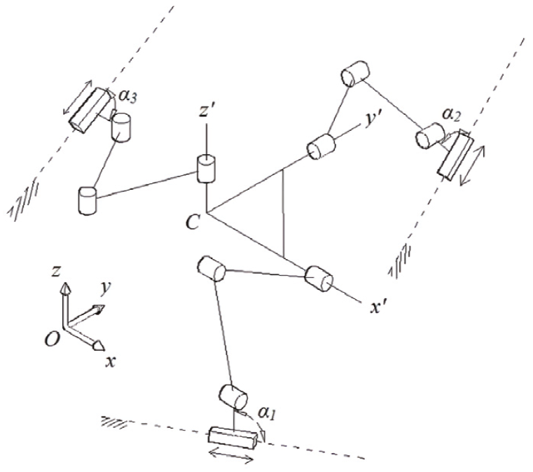
Each leg constrains two rotations. Therefore, the 3-PRRR configuration is an over-constrained mechanism. The terminal revolute joints of the three legs are connected to the mobile platform such that their axes are orthogonal. The most influential design parameters of the 3-PRRR are angles α1, α2, and α3 (Gosselin et al., 2004b). These angles determine the output resolution as well as the overall shape of the mechanism. The three resolutions are equal when α1 = α2 = α3 as well as the elements of the diagonal Jacobian matrix; the resulting mechanism is assumed to be isotropic (Zanganeh & Angeles, 1997). Moreover, the mechanism behaves exactly as a serial Cartesian mechanism when α1 = α2 = α3 = 0 (X-Y-Z stage) (Gosselin et al., 2004b).
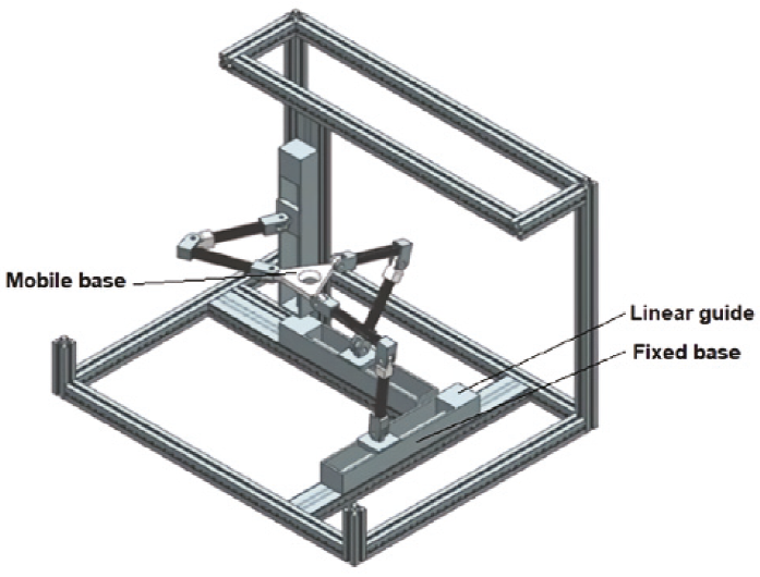
Assembly mode of the machine
The forward kinematic of the 3-PRRR PKM yields an eight-degree polynomial in px (Kim & Tsai, 2003). Therefore, it is possible to build eight different assembly modes from the same mechanism. The Z actuator can be located anywhere perpendicular to the X-Y plane. The limbs that connect the moving platform and the XYZ actuators could have the “elbow” facing either up or down. Figure 2 shows the practical assembly mode proposed in the present work.
Coupled and decoupled base proposals
Two approaches are proposed to determine which variant provides greater dynamic rigidity:
Proposal 1: Keep the base that supports the fixed workpiece to the tool’s base (Figure 3a).
Proposal 2: Detach the base that supports the fixed workpiece from the tool’s base (Figure 3b).

Vibrating modeling and resolution of the motion equations
The vibrating model for all the proposals was obtained from grouping the PKM’s components considering them as groups of mass elements with an associated stiffness and damping capacity. Thereafter, we shall derive the governing equations of motion for each subsystem via the force-balance method.
To obtain the governing equations of motion, we use the generalized coordinate x measured from the system’s static equilibrium position. Gravity forces are not considered below since the coordinates are measured from the static equilibrium position.
The parallel kinematic machine is described via inertial elements, m, along with discrete spring elements, k, and damper elements, c. All inertial elements translate only along the i direction. The external force Fc(t) in the i direction is a representative disturbance acting on the tool due to the uncut material. The free-body diagrams are used to apply the force-balance method to each inertial element.
Modeling method and FEM modal analysis
Coupled base proposal: One degree of freedom system
The decoupled base proposal with one degree of freedom (DoF) is the starting point for all other cases since some values from this case are used in the other ones. This model encompasses the workpiece and its base in just one mass-spring-damper subsystem. Another subsystem encompasses the machine structure, the tool, and the toolholder. The cutting force is modeled in the contact zone between the cutter and workpiece during the cut (Figure 4).

Figure 4 assigns elements by colors to the vibrating model. Yellow-colored components correspond to m1, k1, and c1, while the blue-colored ones correspond to m2, k2, and c2. This model has only 1 DoF, and this is obtained by assuming that the tool displacement (x1) will be equal to that of the workpiece (x2), and assuming that the tool and the workpiece will be always keep in contact during the cutting process.
The motion equation for the system is:
Coupled base proposal: Two degrees of freedom system
The coupled base proposal separately encompasses the elements that conform to the structure of the tool, the workpiece, and the base by considering that the first two are not directly connected to the ground, but are rather fixed to a common base, which is concurrently connected to the ground (Figure 5).

Figure 5 assigns elements by color to the vibrating model: Blue-colored components correspond to elements m1, k1, and c1; yellow-colored ones correspond to m2, k2, and c2; and gray ones correspond to m3, k3, and c3.
Three mass-spring-damper systems can be observed in which two masses (m1 and m2) are joined to the same base (m3). By considering the displacement equality between the workpiece and the tool (x1 = x2), because of the cutting force connection between them (Figure 5), a two degree of freedom system is in place with these 2 DoF being described by x1 and x3.
The motion equations for the system are:
with an equivalent representation in matrix form:
Or:
Here
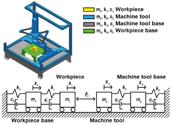
Decoupled bases proposal: Three degrees of freedom system
In this proposal, the two mass-spring-damper system in series are present: One corresponds to the tool and the other one to the workpiece.
Figure 6 assigns elements by color to the vibrating model. Yellow components correspond to elements m1, k1, and c1; blue ones correspond to m2, k2, and c2; gray ones correspond to m3, k3, and c3; green-colored ones correspond to m4, k4, and c4. In this vibrating model, a total of four mass-spring-damper systems are present and grouped by pairs. Mass pairs are connected via the cutting force similar to the two degrees of freedom system; therefore, x1 equals x2 for a total of three degrees of freedom described as x1, x3, and x4.
The motion equations for the system are:
Or:
Here
Obtaining modal parameters and resolving motion equations
Mass is obtained by employing NX software via the materials shown in Table 1. This leads to the magnitudes shown in Table 2.
Table 1: Materials of the solid model in NX
| Subsystem | Component | Material |
|---|---|---|
| Workpiece | Legs (profiles) | Aluminum 6061 |
| Table | Steel | |
| Workpiece holder | Steel | |
| Workpiece | Steel | |
| Tool | Machine structure (profiles) | Aluminum 6061 |
| Linear guides | Steel | |
| Joints | ABS | |
| Links | Aluminum 6061 | |
| Table | Brass |
Table 2: Mass values
| System | Mass | Magnitude [kg] |
|---|---|---|
| 1 DoF | m1 | 305.1013 |
| m2 | 11.8083 | |
| 2 DoF | m1 | 50.208 |
| m2 | 4.2585 | |
| m3 | 302.3477 | |
| 3 DoF | m1 | 4.2585 |
| m2 | 50.2080 | |
| m3 | 254.8933 | |
| m4 | 7.5490 |
The concept of natural frequency relates mass to stiffness. By already knowing the value of each of the model’s masses, it is only matter of finding the natural frequency value associated with each mass-spring-damper system. This value was obtained via FEM. The mesh parameters used for the simulation are shown in Table 3.
Table 3: Mesh parameters
| Subsystem | Elements size [mm] | Component | Bodies | Material |
|---|---|---|---|---|
| Workpiece | 10 | Legs (profiles) | 4 | Aluminum 6061 |
| 10 | Table | 1 | Steel | |
| 10 | Workpiece holder | 2 | Steel | |
| 10 | Workpiece | 1 | Steel | |
| 10 | Machine structure (profiles) | 16 | Aluminum 6061 | |
| Tool | 15 | Linear guides | 3 | Steel |
| 10 | Joints | 16 | ABS | |
| 5 | Links | 6 | Aluminum 6061 | |
| 15 | Table | 1 | Brass | |
| 10 | Legs (profiles) | 8 | Steel |
Subsequently, the concept of critic damping is employed for a 1 DoF mass-spring-damper system, assuming an underdamped operation with a damping factor of 0.5.
The subsystems from the 1 DoF case are the simplification of the subsystems from
the 3 DoF case. Thus, the stiffness constant and equivalent damping were
employed to obtain the stiffness and damping values of the 3 DoF model as well
as the supposition where
Finally, the mass, stiffness and damping values corresponding to the subsystems supported by the bases were set equal between these 2 DoF and 3 DoF systems because the difference between the 3 DoF and 2 DoF systems comes down to the bases (the systems above these are the same). However, since the 2 DoF system’s base shows a remarkable geometric similarity with the 3 DoF system’s tool base, the mass values, stiffness, and damping values were set equal. The stiffness and damping values associated with each model are shown on Table 4.
Table 4: Stiffness and damping values
| System | Stiffness | Magnitude [N/μm] | Damping | Magnitude [N∙s/m] |
|---|---|---|---|---|
| 1 DoF | k1 | 0.183945 | c1 | 0.007941 |
| k2 | 0.177989 | c2 | 0.001449 | |
| 2 DoF | k1 | 0.258531 | c1 | 0.010528 |
| k2 | 1.049272 | c2 | 0.008542 | |
| k3 | 0.637595 | c3 | 0.025965 | |
| 3 DoF | k1 | 1.049272 | c1 | 0.008542 |
| k2 | 0.258531 | c2 | 0.010528 | |
| k3 | 0.637595 | c3 | 0.025965 | |
| k4 | 0.214349 | c4 | 0.001745 |
Cutting force
Machining conditions that produce discontinuous chips cause variations of the cutting forces. Therefore, the stiffness of the cutting tool holder and the machine tool is of major importance in avoiding vibrations that deteriorate the surface finish. During milling, the process of cutting by each tooth is periodically interrupted and the traverse cross section of the undeformed chip is variable (El-Hofy, 2014). Thus, by assuming a face milling operation, a nonsymmetrical bilateral case of an entrance angle ϕ1, and leaving angle ϕ2, the chip mean thickness can be calculated on a single tooth from the equation:
where
where fz is the feed per tooth and Zc is the number of teeth.
Table 5 summarizes the cutting parameters considering some middle power cutting parameters according to Table 2.4 in (Isakov, 2003).
Motion equations resolution
The motion equations for the vibrating models were obtained via the Euler method for differential equations defining position and velocity in function of velocity and acceleration, respectively, associated with a step size hp. A big step size can lead to a wrong approximation in the direct mathematic outcome. On the other hand, a small step size offers a better approximation although it requires more time for its resolution. One way to establish an appropriate step size within mechanical systems is to make a phase space graph with displacement and velocity as variables.
The lack of dissipation elements in a vibrating system causes a cyclic response that does not allow reduction in neither displacements nor velocities. This generates closed curves in displacement versus velocities graphs. This phenomenon is useful to define the adequate step size for the differential equations to solve. By evaluating many step size values, we found that hp=0.001 is sufficient, since this value already reflects the cyclic behavior of the displacements and velocities of a 1 DoF vibrating system with no dissipation elements present.
The resolution of the previously mentioned equations was developed by employing Euler’s method for differential equations by starting off from initial values (t = 0 s) with a 0.1 μm value for each one of the displacements (x1, x2, x3, etc.) and a 0 μm/s value for each velocity (v1, v2, v3, etc.). Furthermore, gathering the mass, damping, stiffness, and natural frequencies values was supported by finite element simulation with NX Software and making use of NX Nastran solver with a structural type analysis using “SOL 103 Response Simulation” solve tool.
Numerical method for the 2 DoF model (Coupled base)
We next employed the Euler method for resolution of differential equations:
Where:
Being
Numerical method for the 3 DoF model (Decoupled bases)
We next employed the Euler method for differential equations resolution:
While, for the displacement matrix:
Where:
With:
Results
The results were obtained using equations (9) and (11) for the 2 DoF system, and equations (12) and (13) for the 3 DoF one. Figure 7 shows displacements for x1, x3, and x4 within the initial 200 s of the milling operation. The maximum values are close to 7000 μm with a significant difference for x3. Figure 8 shows the displacement response along 1000 s. This behavior has a period of 400 s.

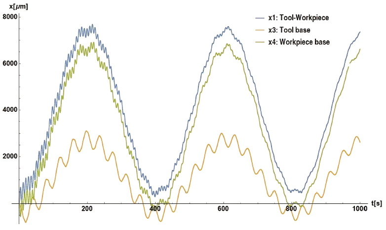
Figure 9 shows the behavior of velocities v1, v3, and v4 along 200 s. The maximum values are close to 300 μm/s with a significant difference in magnitude for v3. The v3 maximum values match with v4 minimum values on each cycle. Figure 10 shows the velocity behavior previously mentioned along 1000 s, which allows observation of the stabilization that occurs progressively except for v3, which seems to maintain the same behavior and magnitudes throughout.
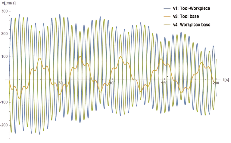

Figure 11 shows the displacement behavior of x1 and x3 along 200 s. These have the maximum values around 6000 μm/s and 5000 μm/s, respectively. Figure 12 shows the displacement behavior of x1 and x3 along 1000 s. This behavior has a period of 180 s.
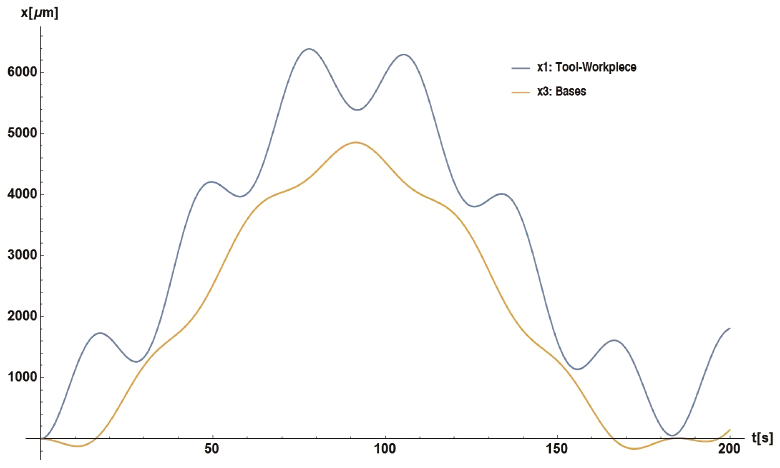

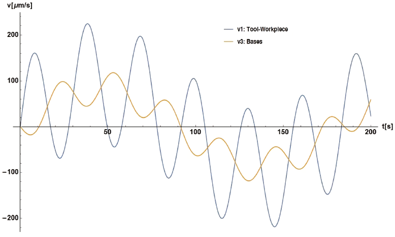
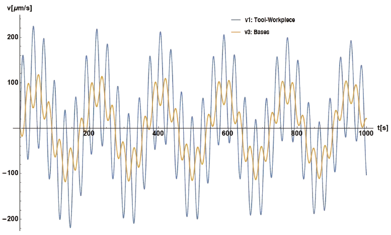
Figure 13 shows velocities v1 and v3 along 200 s with maximum magnitudes close to ±200 μm/s for v1, while v2 shows maximum values of half that magnitude. Figure 14 shows velocities v1 and v3 along 1000 s with a period of approximately 180 s. In this case, the velocities do not have significant damping.
Discussion
In the first instance, the maximum values for displacement and velocity from the 2 DoF system are lower than those for the 3 DoF system. Nevertheless, that fact does not necessarily means that it is better; the maximum displacements and velocities correspond to the variable associated with the interaction between the tool and workpiece subsystems. The values oscillate between 7600 [μm] and 280 [μm/s] in the decoupled bases, while in the coupled base proposal, these values oscillate between 6400 [μm] and 220 [μm/s], which is 1.57 % less for displacements and 21 % for velocities both with respect to the 3 DoF system.
On the other hand, the general behavior of the displacements in the 3 DoF system is repeated in longer periods (every 400 seconds, approximately), but it is repeated in shorter periods (every 200 seconds, approximately) in the 2 DoF system. This can be interpreted as behaviors with smaller frequencies for this first system, and greater ones for the second one. This means that the decoupled base proposal will reach its maximum displacements in a longer period compared to the coupled base proposal. Therefore, these values for maximum displacements in the 3 DoF system will be prevented more easily via constant cutting times below 200 seconds.
The 3 DoF system has an overall better damping than the 2 DoF one; hence, displacements at lower velocities can be expected as the cutting process advances through time in this first system. In the second system, velocities do not achieve a significant reduction in value. Nonetheless, by considering the factors mentioned in the previous paragraph (cutting operations below 200 seconds), a substantial reduction in velocities could not happen because the first major velocity reduction does not appear until 320 seconds. The velocities are 44 % lower than the initial ones.
The decoupled base proposal shows an overall better performance under these considerations. A simplified solid model of the proposal can be observed in Figure 15.

The results for the displacements and velocities in both design proposals are too large for machining with industrial standards. Nevertheless, this can be broadened to the PKM modeling because this only represents the two inertial elements instead of making a model that englobes each component of the real system as an additional inertial element. This great scale response can be translated as the sum of displacements associated with diverse components of each subsystem. This is only for the displacements present in the real interaction between tool and workpiece.
Furthermore, the validity of the natural frequency values obtained via simulation for the different elements of the solid models was evaluated by making theoretical calculations of the natural frequency for a rod-type structure without any support (made out of steel with square cross-section with 20 [mm] per side and a length of 400 [mm] as well as ρ=7829 [kg/m3] and E=206.94 [GPa]). We then compared theoretical values with the ones obtained by the simulation. We compared the lower value of natural frequency associated with each natural vibration mode to obtain the results shown in Table 6.
Table 6: Error associated with the natural frequency calculations via simulation
| Mode | fsim [Hz] | fanalyt [Hz] | Error [%] |
|---|---|---|---|
| 1 | 654 | 661 | 1.11 |
| 2 | 1774 | 1821 | 2.62 |
| 3 | 3400 | 3571 | 4.83 |
| 4 | 5465 | 5903 | 7.45 |
| 5 | 7904 | 8826 | 10.47 |
Table 6 shows the values obtained by simulation (fsim) and the values obtained analytically (fanalyt). The data show how the error increases alongside the normal vibration mode at issue. However, an error of approximately 1.11 % is totally acceptable because the lowest natural frequency of each assembly was always used (the one associated with the first normal vibration mode).
Conclusion
This paper describes structural analysis of a 3 degree of freedom parallel kinematic machine. The theoretical results were used to demonstrate the viability of the modeling approach. The proposed model provides an effective guide to design milling machines with the best architecture and enhancing performance. Two assembly proposals were modeled and analyzed. The decoupled base design proposal has a better performance characteristic to develop machining operations. It can maintain a cutting operation without displacement peaks due to greater operation times and better damping response.

