


 nueva página del texto (beta)
 Inglés (pdf)
 Artículo en XML
 Referencias del artículo
 Enviar artículo por email
 Citado por SciELO
  Similares en
SciELO
Similares en
SciELO 
 Permalink
Introduction
The demand for energy has raised in the modern world due to overpopulation. This scenario, together with the shortage of fossil fuels, have given rise to the development of new methods for energy transformation during the past decades. The primary goal is to utilize the higher amount of energy available inside the fuel or source, which will result in technologies that are more efficient. For the past decades, the boom of renewable energy has exponentially increased with solar panels and wind turbines as the most known technologies, but there are many others that are trying to join the seek of solutions, like the wave energy converters. The topic of this document is the Stirling engine which has the characteristics of an external combustion engine but the advantage of clean energy conversion.
The Stirling engine was invented in 1816 by the Reverend Robert Stirling (Walker, 1980), at that time the machine was better known as a “Hot Air" engine. Although for that time the device occupied relatively unimportant role among other engines, now the Stirling engines rearise due to their high efficiency, their capacity to use any source of heat (including solar energy), their quiet operation, and non-polluting character. These represent a notable advantage to the energetic crisis, and that is the reason for the increasing number of works focused on developing this technology.
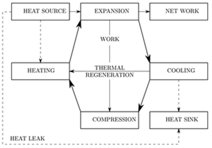
A Stirling engine is a thermo-mechanical device that operates on a closed regenerative thermodynamic cycle (there is no change in mass inside the engine) with cycle compression and expansion of the working fluid (Figure 1) at different temperature levels (Martini, 1983). This last description includes a wide variety of configurations, functions, and characteristics. It include both reciprocating and rotary systems generated by different simple and complex mechanisms. They are classified into kinematic (beta, alpha and gamma) and dynamic, which includes free piston Stirling engines. A kinematic Stirling engine uses a classic crank mechanism with a flywheel to produce a 90°out of phase reciprocating motion of the piston parts. These type of Stirling engines are the most studied until now and there are well-resumed works on both theoretical and experimental studies (Ipci & Karabulut, 2018; Cheng & Chen, 2017; Altin et al., 2018; Sowale et al., 2018; Çınar et al., 2018, among others).
The micro-cogeneration (µCHP) is one of the principal applications, although there are many others like vehicle propulsion to produce a zero or low level of pollution, to directly pump blood, generate electricity, or generate hydraulic power, as summarized by Valenti et al. (2015). Some articles (Zhu et al., 2018; Remiorz et al., 2018) investigated if a µCHP, based on a Stirling engine, life-cycle costs, emissions, and energy requirements in a domestic house. Conroy et al. (2014) found that operating a WhisperGen Mk IV Stirling engine unit in the house resulted in an energy saving of 2063 kW h of electricity and generated a thermal output of 20095 kW h during the trial period, operated for 2512 h and produced an annual saving of 180 euros; also there was a decrease in the
The FPSE is distinctive for the reason that it excludes all wearing mechanisms related to a kinematic Stirling engine and thus eliminates the need for lubricant. It replaces the crank mechanism of the kinematic Stirling engine by a linear mechanical storage device such as a compression spring. FPSE provides the possibility of an extremely long operating life, higher efficiency and zero maintenance (Deetlefs, 2014). Some works are found in the literature, showing the use of renewable energies using FPSE (Motamedi et al., 2018; Langdon et al., 2017; Bartela et al., 2018). Other researchers are interested in the design, but fixing parameters like frequency (Zare et al., 2016) or using scaling laws (Formosa & Fréchette, 2013).
The successful design of a Stirling engine, and particularly FPSE, requires accounting the complex interaction between different types of processes, being the principal: the heat transfer at the different heat exchangers, the mechanical forces that link the different piston-displacer movements, which determine the dynamics of the engine, and the thermodynamics of the working fluid. It is for this reason that different approaches, with different simplifications, have been developed. These can be classified into: zero-order methods, which proposed simplified and empirical correlations to estimate the power output of engines; first-order methods that assume ideal heat transfer processes at the heat exchangers; second-order methods that include the heat transfer limitations at the heat exchangers; third-order methods that assuming one dimensional variations apply balances at a number of control volumes; and multidimensional analysis which uses CFD solvers for the analysis of the engine (Dyson et al., 2004).
The mentioned methods focus on the thermodynamics of the engine, and reflect good results under specified conditions, especially if the piston-displacer movements are imposed, for example by a crank mechanism. However, in the case of free piston engines, the dynamics of these components should be determined by solving additional equations that reflect these interactions. In this sense, the works of Zare et al. (2016), present a successful approach to integrate these phenomena, identifying that the key complication to design useful FPSE is to assure the stability of the oscillations. This is not a minor mission because of the decoupled pistons and the sensibility of some parameters. Therefore, this research aimed to continue the analysis of the coupling between the kinematic and dynamic constraints, and thermodynamics in FPSE. For this purpose, a mathematical model was developed including the dynamic equations for stability analysis of FPSE. The code allowed analyzing a set of parameters that guide the design of an engine, a power output of 1 kW was set as a design objective, and a genetic algorithm optimization was implemented to solve the optimization problem.
Development
The Stirling cycle
The Stirling cycle is an ideal thermodynamic cycle built by two isothermal curves and two isometric regenerative processes. To fully understand the complete cycle, each one of the processes is described in the following.
Let's have in mind the two pistons shown in Figure 2 on each end of the cylinder and among them a regenerator, which may be thought as a thermodynamic sponge, releasing and absorbing heat alternately.
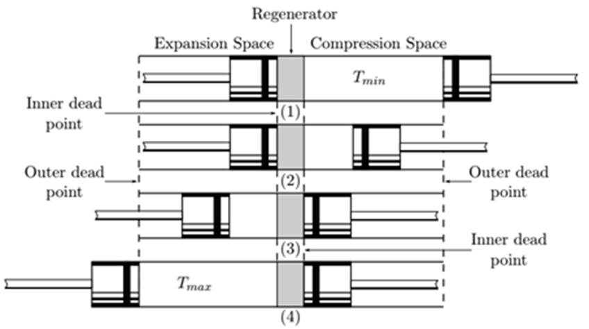
One of the volumes between the regenerator and a piston is called the expansion space, and it's maintained at a high temperature (
It is essential to get the initial configuration of the pistons and the fluid, to describe the cycle; thus, the following assumptions are made:
As an initial configuration, imagine the compression space piston is at the outer death point and the expansion space piston is at the inner death point (near the regenerator).
All the fluid is at the compression space.
At this position, the volume is a maximum.
The pressure and temperature are minimum values.
The four Stirling cycle processes are described below (Figure 2):
Process 1-2: Caused by the movement of the compression piston and the lack of motion of the expansion piston, the working fluid is squeezed. At the same instant, the temperature remains constant due to the transfer of heat (
Process 2-3: Also named as transfer process, both pistons move, the compression piston towards the regenerator, and the expansion piston simultaneously away. So, the volume remains constant. Now the fluid is passing through the regenerator, the compression space to the expansion space. Also, the fluid is heated up while moving, from
Process 3-4: Now the expansion piston keeps moving to the outer death point, and the compression piston remains stationary at the central death point. As the volume increases, due to the incorporation of heat (
Process 4-1: Another transfer process describes the closure of the cycle, as in process 2-3 the pistons move simultaneously enclose the same volume and transfers the fluid back to the compression space but passing before through the regenerator. Therefore, a change in temperature occurs as before but in the opposite direction which means
Schmidt analysis
The Schmidt cycle is the most complicated case to find an analytical solution; all the remaining studies must be solved numerically due to their restrictive assumptions. It gets its name after Gustav Schmidt, who published this analysis in 1871.
The analysis is based on mainly five assumptions:
The working fluid obeys the ideal gas law
The mass inside the engine is constant
The instantaneous pressure is consistent within the working space
There are isothermal regions throughout the engine
The piston and displacer motions behave sinusoidally
Eq. (1) shows the pressure as a function of the compression (Vc) and expansion (VE) volumes.
Where:
VC = Compression volume
VK = Cooler volume
Vr = Regenerator volume
Vh = Heater volume
VE = Expansion volume
TC = Compression temperature
TE = Expansion temperature
P = Pressure
R = Gas constant
M = Total mass inside the engine
From assumption 5, the volumes are periodic function; thus, the work done per cycle W is shown in Eq. (2) and the integration is carried out over the common period of the volumes.
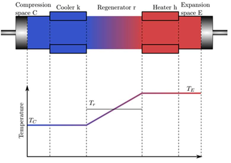
Figure 3 shows the temperature variation within the regenerator T r , which is determined by Eq. (3). Also, the temperature in the compression space and cooler space is the same due to the assumption of isothermal regions. Similarly, the heater space and expansion space have the same temperature.
Dynamics of free piston Stirling engine
The study of Stirling engines is a multidisciplinary task. It includes knowledge from solid mechanics, fluid mechanics, and heat transfer. Since the difference in temperatures and the motion of the pistons within the cylinder together determine the pressure variation, the analysis should be studied as a whole and not only the solid mechanic part but the thermodynamic phenomena.
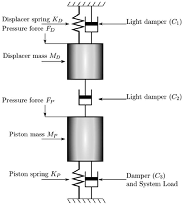
FPSEs are more complicated due to their multiple degrees of freedom (DOF) compared to standard inside combustion engines. They are constituted by three masses, although in many cases, the piston or cylinder is fixed to the ground, so the three DOF reduces to two. Additionally, various springs and dashpots connect the moving devices.
Figure 4, shows two masses: one for the piston (P) and the other for the displacer (D), three dashpots and two springs of stiffness
Equations of motion
Because FPSE lack of mechanical connections, the analysis of this type of machines must have a pre-study before applying the first-order analysis. The most significant difference between the FPSE and the kinematic engines is that the piston and displacer strokes are unspecified, as well as the phase angle. Not only the fact that the amplitudes are unknown is hard to lead but also the dependence of these parameters with loads adds more complexity to the study. Therefore, the study of the dynamics is fundamental and thus it is the first step.
The approach used in this section is based on variational calculus, attributed to Leibniz and Lagrange and it is referred to as analytical dynamics. It considers the system as a whole rather than its individual components, two fundamental quantities, the kinetic energy, and work, both of which are scalar quantities. Since the purpose of the document is to analyze the engine, the demonstration of the method is not covered. Hence the study begins with the Lagrangian equation (Meirovitch, 1998).
Where L is the Lagrangian and
Where
The potential energy of the system is divided into the displacer potential energy (
The total potential energy (VTOTAL) is described in eq. (11).
The non-conservative forces described on eq. (5) are also divided into two, thus there are only two degrees of freedom. First, the non-conservative forces for the displacer are shown in Eqs. (13)-(15).
Similarly, the non-potential forces acting on the piston are described in Eqs. (17-19).
Finally, Eq. (4) is used in order to find the equations of motion:
Where,
Stability analysis of free piston Stirling engines
A stability analysis is presented as an essential step to study how different design parameters influence the behavior of the thermomechanical machine (Kwankaomeng et al., 2014).
The section starts with the new dynamic model, which includes a new velocity-dependent mechanical loss. The latter is included with the purpose of studying how the motion of the pistons influence each other. The mathematical tool used is the Laplace transform, due to its simplicity of implementation and above all for the study of the localization of the poles.
The main obstacle to designing functional Stirling engines is to guarantee the stability of the oscillations, which is not a trivial task due to the decoupled pistons and the sensibility of some parameters. There is a list of tips presented in (Walker, 1980) although most of them are assuming the construction of the machine.
Based on the analysis made by Redlich and Berchowit (1985), a more complete dynamic system described in Eqs. (20) and (21) is now studied. The spring constant between the displacer and the piston is assumed negligible in comparison to the mechanical piston spring constant and the mechanical displacer spring constant.
Eqs. (28) and (29) are deduced.
Important parameters of the system are the frequency and the dynamic losses (Redlich & Berchowit, 1985), Eqs. (30) and (31).
The poles of the system are calculated from Eqs. (32) and (33), which are the roots of the polynomial.
Depending on the localization of the poles ωc can be calculated from Eq. (36). Figure 5 graphically shows the values of the roots and how these influence the value of ωc.
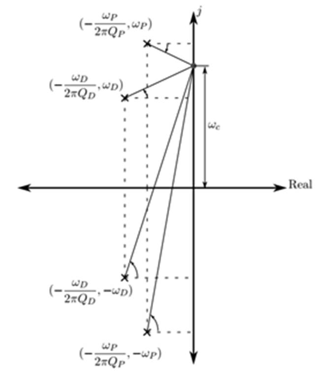
Redlich determined that the next criteria must be fulfilled in order to maintain oscillations within the cylinders (Eq. 37).
Thermodynamic study
Beta type machines differ from the alpha type due to the compression space, which depends on the displacer and piston motion. Eqs. (38) and (39) describes both volumes (Urieli, 1984a).
Where:
Later in the analysis, the variation of the compression and expansion volumes with respect to the cycle will be used to compute the work done and thus the power.
Urieli (1984b) presented a mathematical technic to simplify the explicit pressure form in eq. (40).
After applying some trigonometric identities and rearranging some terms, the result is Eq. (43).
New equalities to simplify Eq. (43). The graphic representation of the angle (β) and the hypotenuse (c) are also shown Figure 6.
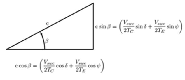
Substituting Eqs. (44) and (45) in eq. (43):
Then, the work of the engine can be calculated from eq. (47) and (48).
From eq. (45) the total work is calculated.
Design parameters for a 1kW FPSE
Evolution has played the primary role in nature, the mixing and mutation of genes create new combinations in the DNA, despite the similar characteristics, a new offspring can be better than its predecessor. This is the foundation for the Genetic Algorithm.
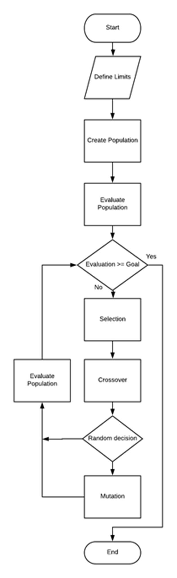
The algorithm tries to mimic the logic of nature; the more fitted chromosomes are allowed to “reproduce" their genes to form a next and probably a better generation and the less capable “died" then the new generation repeat the cycle, so the enhancement of the species continues, on this case till the convergence of a solution. The implementation of the algorithm simplifies the natural evolution in five steps (Mallawaarachchi, 2017). See Figure 7 for a better understanding of the algorithm:
Initial population: To begin with the algorithm it is necessary to create the first generation of individuals, each of them is a particular solution for the problem tended to solve (not necessarily a good solution). These individuals are described by a set of parameters named genes that are equivalent to variables; a collection of genes creates a chromosome that is a solution.
Fitness function: A fitness function determines how capable an individual compares to the rest of the population; each is graded, and this will determine the availability to reproduce itself.
Selection: As natural selection determines how a population could grow and the fittest individual can pass their genes to the next generation, something similar occurs with the population in the algorithm, based on their fitness function score they either are killed or allow to reproduce.
Crossover: Crossover is used to mix some genes from their parents to a couple of newborn individuals with new genes and probably with better capabilities, in the algorithm how genes mix can be defined either arbitrary or in a deterministic manner.
Mutation: Stagnation in the community can be prevented using a method called mutation, although it is used randomly also is found to be helpful. It consists of modifying specific genes with a different value thus it enhances a significant diversity in the population.
Based on the five steps mentioned earlier, a code is developed with the purpose of pursuing a set of parameters, which enables the engine to generate a power output of 1 kW.
Results and discussion
The results shown in Table 1 represent the implementation of the first-order analysis for a beta type engine, based on Urieli's work, and the stability analysis considering the loss between the power piston and the displacer. The error presented compares the first order analysis and the stability study developed with the Schmidt analysis deduced from Urieli (1984a).
Table 1: Design parameters for a 1kW FPSE
| Núm | Cyl. area (m^2) | Rod area (m^2) | Charge press. (Bar) | Cooler Temp. (K) | Heater Temp. (K) | Piston mass (kg) | Displacer mass (kg) | Piston spring stiffness (N/m) | Displacer spring stiffness (N/m) | Freq. (Hz) | Phase angle (Rad) | Power (W) | Error (%) | ||
|---|---|---|---|---|---|---|---|---|---|---|---|---|---|---|---|
| 1 | 0.0091 | 0.0016 | 6.758464 | 322.2406 | 1116.68 | 1.0544 | 0.2541 | 1969.9066 | 1919.6185 | 9.239 | 1.9371 | 1010.87 | -0.05 | ||
| 2 | 0.0204 | 0.0008 | 6.577653 | 439.3334 | 981.397 | 2.1052 | 1.6476 | 675.6721 | 1011.0944 | 2.415 | 1.9431 | 1064.22 | 0.3173 | ||
| 3 | 0.0124 | 0.0008 | 6.874775 | 489.0427 | 1136.18 | 2.3059 | 0.6414 | 906.4282 | 1830.083 | 4.934 | 1.7558 | 868.51 | 0.5928 | ||
| 4 | 0.0225 | 0.003 | 5.71042 | 492.3117 | 900.127 | 1.045 | 1.3351 | 576.5377 | 1375.2158 | 2.893 | 1.722 | 1015.95 | -12.48 | ||
| 5 | 0.009 | 0.0003 | 6.878591 | 335.8463 | 1057.27 | 2.5074 | 0.2277 | 852.8553 | 1931.3532 | 8.343 | 1.6572 | 1010.62 | 0.6071 | ||
| 6 | 0.0249 | 0.0027 | 1.540996 | 303.4345 | 1018.95 | 2.6616 | 0.3165 | 544.3997 | 1277.6503 | 5.722 | 1.6459 | 989.201 | -0.691 | ||
| 7 | 0.0273 | 0.0066 | 1.705393 | 397.7975 | 1152.47 | 2.9107 | 0.3609 | 583.056 | 988.0791 | 4.985 | 1.716 | 997.08 | -4.658 | ||
| 8 | 0.0138 | 0.0038 | 4.51109 | 439.5299 | 973.728 | 1.5836 | 0.1942 | 894.4902 | 1730.9642 | 8.785 | 1.6801 | 1003.82 | 0.8297 | ||
| 9 | 0.0249 | 0.0058 | 3.033995 | 380.244 | 916.188 | 0.6708 | 0.8787 | 581.1874 | 1544.6524 | 2.619 | 1.9661 | 769.969 | 2.5703 | ||
| 10 | 0.011 | 0.0054 | 5.094746 | 448.0015 | 1171.28 | 2.0799 | 0.1043 | 2026.1392 | 1739.172 | 14.12 | 1.8363 | 1001.99 | -0.02 | ||
| 11 | 0.0201 | 0.0026 | 5.360449 | 403.1546 | 1074.39 | 1.0112 | 1.3884 | 304.6936 | 1622.2275 | 1.448 | 1.7892 | 525.892 | -0.443 | ||
| 12 | 0.0299 | 0.0028 | 1.036066 | 369.4373 | 828.76 | 1.4359 | 0.4718 | 1375.3947 | 1210.4832 | 5.97 | 1.9334 | 983.189 | -12.31 | ||
| 13 | 0.0176 | 0.0076 | 6.80081 | 357.5295 | 669.773 | 1.1283 | 0.3908 | 385.0678 | 1203.0731 | 4.779 | 1.5926 | 997.921 | 0.7554 | ||
| 14 | 0.0158 | 0.0037 | 2.420829 | 420.3085 | 1138.66 | 2.9003 | 0.8034 | 834.2437 | 1293.708 | 3.886 | 1.854 | 368.62 | 0.0331 | ||
| 15 | 0.0362 | 0.0071 | 1.330347 | 319.6724 | 1109.9 | 1.417 | 0.8711 | 690.3573 | 792.5066 | 3.25 | 1.91 | 1042.68 | 1.0819 | ||
| 16 | 0.0181 | 0.0062 | 6.00861 | 300.4698 | 1143.28 | 0.9532 | 0.5657 | 350.0767 | 599.9818 | 3.096 | 1.7097 | 998.62 | 0.5184 | ||
| 17 | 0.023 | 0.0002 | 3.992044 | 496.8031 | 764.759 | 2.5184 | 1.0459 | 851.0623 | 1154.4598 | 3.301 | 1.94 | 988.495 | 2.6773 | ||
| 18 | 0.0158 | 0.0001 | 3.009427 | 345.7366 | 1159.32 | 1.5142 | 0.2699 | 209.7209 | 1964.409 | 6.428 | 1.4571 | 989.627 | 2.3484 | ||
| 19 | 0.0103 | 0.0006 | 5.262286 | 312.2817 | 1024.37 | 1.503 | 0.1273 | 391.0977 | 1223.0295 | 8.441 | 1.5832 | 1003.96 | 0.865 | ||
| 20 | 0.0173 | 0.0023 | 5.634158 | 426.0448 | 1030.97 | 1.4131 | 0.7294 | 625.3536 | 1120.9107 | 3.697 | 1.7678 | 998.789 | 0.1179 |
Table 1 shows twenty different combinations of parameters, which represent twenty different engines working in a stable mode, and with power outputs closer to the desired 1 kW. There are also some designs with lower power outputs, like the engines 11, and engine 14. This indicates that under certain conditions, there is a maximum limit for the power output that would not affect the stable operation of the engine. In the case of engines 11 and 14, this limit is 525 W, and 368.62 W respectively.
The proposed procedure doesn’t explore in detail the influence of a particular parameter, the objective is to search through all the potential designs, ensuring the stability of each proposed engine. This represents a valuable tool for early-stage design of FPSE.
In general, the error for the predicted power is lower than 1 % for the majority of the simulations, which validates the proposed models.
Figures 8 and 9 show the variation of the volume inside the compression and expansion spaces for engines 3, and 12, a pair of engines enlisted in Table 1. Pressure-Volume diagrams for the mentioned engines are presented in Figures 10 and 11.
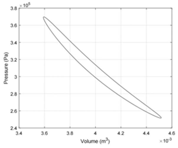
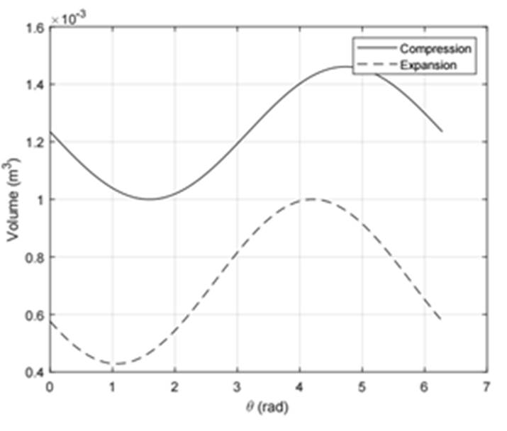
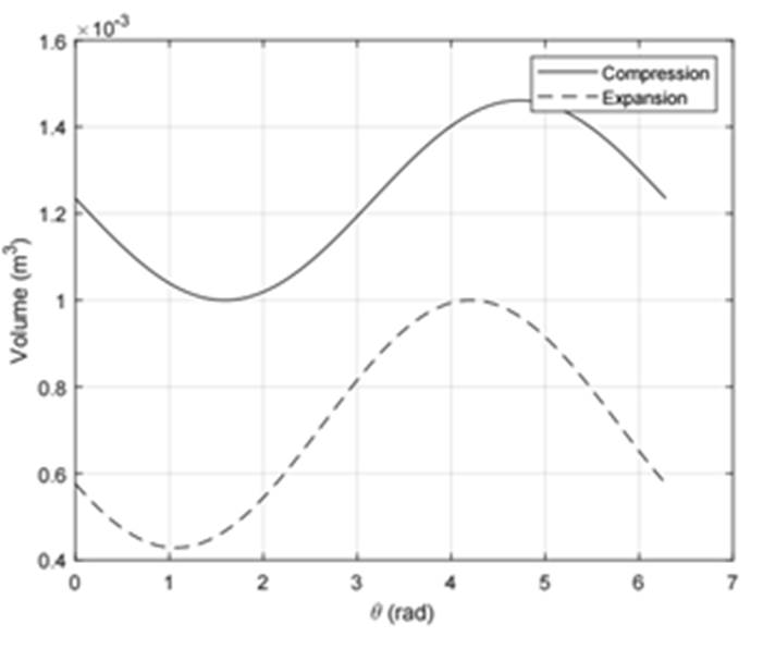
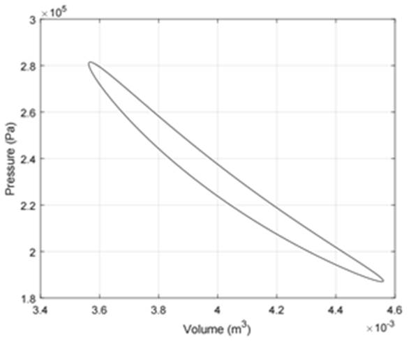
Figures 10 and 11 reflect the characteristic shape for a PV diagram in Stirling engines. This shape differs largely from the theoretical PV cycle and thus indicates the relevance of using adequate tools to analyze Stirling cycles.
Some conclusions can be inferred from this kind of diagram. For example, according to Figures 8 and 9, both engines follow a similar volume variation, but the design 3 gives a higher power output. This difference can be explained due to the operation at higher pressures observed in Figure 10 when compared with the pressure levels of engine 12, Figure 11. This supports a known fact about Stirling engines: when two engines present similar geometrical characteristics, the operation at higher pressures translates into higher power outputs.
Conclusions
The combination of stability, dynamic restraints and equation of motions for Free Piston Stirling Engines has been achieved in this work.
Functional designs were obtained assuring the stability of the engine. FPSE results more complicated than the kinetic engines due to the uncoupled pistons, which lead to unknown movements. Therefore, it is crucial for the study to solve the equations of motion first. A small variation in the parameters such as mass and spring stiffness could strongly influence the performance or the proper functioning of the engine.
This work showed that it is critical to consider this sensibility of the system, and consequently, it is essential to apply a stability analysis in order to fully understand the behavior of the thermal machine. Furthermore, it was proved that a genetic search algorithm is a viable method to find a desirable power output.

