


 nova página do texto(beta)
 Inglês (pdf)
 Artigo em XML
 Referências do artigo
 Enviar este artigo por email
 Citado por SciELO
  Similares em
SciELO
Similares em
SciELO 
 Permalink
Introduction
The contribution of Norbert Wiener has had a profound effect on many fields including signal processing, systems, control theory and cybernetics. He is known as the father of cybernetics, which, in his own words, is “the scientific study of control and communication in the animal and the machine (Wiener, 1961)”. Recently, cybernetics has contributed tremendously to the development of intelligent control and the smart management of cyber-physical systems (CPS). Examples of real-life systems considered as CPS are smart grids, automotive and transportation systems, smart healthcare, unmanned aerial vehicles (UAVs), robotics, and the Internet of Things, among others (Lee, 2008; Rajkumar et al., 2010; Haque et al., 2014; Ochoa et al., 2017; Dressler, 2018; Lopez et al., 2018; Alguliyeb et al., 2018; Do et al., 2018).
Typically, a CPS is a smart networked system that is designed to interact with the physical world including human users; this interaction is achieved through its embedded sensors, processors, and actuators (Lee, 2008; Rajkumar et al., 2010; Li et al., 2017). Therefore, emerging technical challenges arise with the rapid increase in functionalities, significant uncertainties and stringent requirements on performance, representation, analytics, smart management, safety, security, flexibility and reliability, modeling, analysis, control, and others; these aspects lead to increasingly complex CPS design (Lee, 2008; Rajkumar et al., 2010). In this way, communication channels are essential for networked control in CPS, since they provide the required information for feedback in the control law. Information on the physical system dynamics is sent to the controller by the implemented sensors using the communication channels. Hence, the efficiency and reliability of communication channels are crucial to developing an adequate control to support real-time and trustworthy CPS applications.
Today, Internet communication has become an essential part of the modern world. The recent progress of communication technologies has led to extensive research on the possible applications of remote-control technology implemented over a communication line in the field of control engineering (Kobayashi et al., 2017; Ochoa et al., 2017; Do et al., 2018). Nevertheless, a networked control system is permanently affected by negative factors, which include induced time-delay and packets losses, typical characteristics during network operation. One possible solution to these issues is updating the network equipment; however, this solution is costly. Another solution is the use of robust and reliable control methodologies needed to decrease the negative impact of time-delay and packet losses. Among these problems, the proposed controller should address other common problems found in CPS, like complex interactions among potentially conflicting actuations, continuous and discrete dynamics with discrete controllers, unknown and unmodeled dynamics, internal and external unknown uncertainties, substantial delays that imply reduced stability regions, unknown variable time delays and so on Yu et al. (2017); Kobayashi et al. (2017).
In recent years, intelligent controllers, particularly those for neural control, have showed the ability to control complex systems subject to the abovementioned complications, even with no exact, incomplete or unknown mathematical models of the system or if the application is complex; therefore, neural control is an obvious methodology for the modeling and control of CPS (Selyunin et al., 2015a & 2015b; Lv et al., 2017). In Jiang et al. (2016), it is presented a deep comparative analysis between the two main methodologies of intelligent control: fuzzy and neural based controllers, then in Farias (2018) it is developed the same comparison with an applicability focused to robotics, these two works illustrate the great capability of intelligent controllers to deal with unknown and unstructured environments, fuzzy controllers are mainly recommended for their simplicity to implementation, besides, fuzzy controller allows the user to include known characteristics of the system by a specialist which cannot be done with neural controllers, however, neural controllers are indicated in complex systems or tasks, where the designer has limited information about the system to be controlled. Use of intelligent control for robotics applications has been deeply studied, for example in Aouf et al. (2019) and Tong el al. (2020) consider implementation of fuzzy controllers for robots, in Pillai & Suthakorn (2019) it is presented a compendium of challenges in motion control of rough terrain rescue robots. In Rios et al. (2017), an implementation of the NIOC scheme applied to a modified HD2® (HD2 is a registered trademark of SuperDroid Robots) is presented, such work presents the simulation and experimental results as well as a comparison of the NIOC scheme with a super twisting scheme. In Villaseñor et al. (2018), a germinal center optimization algorithm is used to find a better set of values for the NIOC scheme designed parameters for its implementation to the HD2®.
The main contribution of this paper is to show how the NIOC scheme is capable of working in different network conditions, mainly in presence of unknown delays, packet losses, disturbances and uncertainties, without their previous knowledge. In order to illustrate applicability of the NIOC, three tests are presented, they are implemented on real-time for a tracked robot platform controlled through a wireless network under different network scenarios: Test 1, direct communication between the computer that process signals and the HD2®, which sends its status through a state vector and receives and applies a control signal calculated by the computer. Test 2 and Test 3 communicate through two different routers connected to an inner network in addition to other services; the network provides Internet connection services to all devices connected to it.
In this work, the networked control strategy is described first, and then, the analysis of robustness towards these negative factors is presented through experimental results. The results are shown in detail and prove that the proposed networked control strategy has strong robustness against unknown dynamics, unknown external and internal disturbances, unknown communication delays and packet losses, the fact of the proposed controller deals with all the above explained conditions can be considered as the main strengths of the proposed NIOC, in this sense the main weaknesses and threats remains in the complexity of the proposed algorithm which implies the need of a robust processor to implement all the elements of the NIOC, what can be expensive, besides the implementation of this kind of controller requires previous knowledge of modern control strategies.
This work is focused on the intelligent control of networked systems. In the first stage, the system to be controlled is identified by a recurrent high-order neural network (RHONN) identifier; then, an inverse optimal control (IOC) is designed based on the mathematical model obtained with the RHONN. The designed neural inverse optimal controller (NIOC) is applied in real time to a networked system for trajectory tracking under three different scenarios.
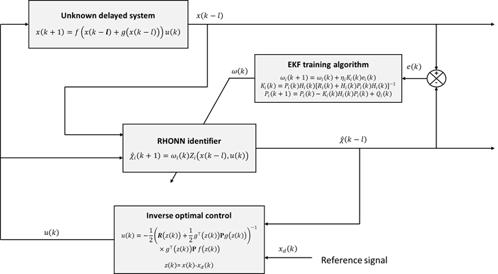
Neural optimal inverse control scheme
This section presents elements of NIOC scheme for unknown discrete-time delayed nonlinear systems. This scheme is composed by a neural identifier trained with an EKF based algorithm, this identifier provides a mathematical model for the unknown delayed system, therefore the obtained neural model is used to design a controller based on inverse optimality technique for trajectory tracking.
First consider the following system:
where:
RHONN Identifier
A RHONN is a generalization of the first-order recurrent neural network known as the Hopfield network. A recurrent neural network has memory and dynamic behavior due to its inner feedback connections. Moreover, in a RHONN, the high-order connections enhance the approximation capabilities, convergence, storage capability and fault tolerance of the neural network (Haykin et al., 2004; Sanchez et al., 2008; Zhang, 2008). The following RHONN identifier based on the RHONN series-parallel model is used to identify system (1) (Alanis et al., 2016):
Where:
n = state dimension
ωi = weight vector of
x is the state vector of the system to be identified, and u is the input vector and the high order terms are defined as:
where x i is the i-th state variable of the system (with i = 1, …, n), l is the unknown system delay and u j is the j-th input component of system input u (with i = 1, …, m) and
where β > 0 and v is a variable with any real value.
It is important to note that the RHONN identifier (2) does not require previous knowledge of the system model to be identified nor information of its disturbances and delays.
The selected training algorithm for the RHONN identifier (2) is based on an extended Kalman filter (EKF). The EKF finds the optimal weight vector that minimizes the prediction error at each iteration, and it is computed between sampling time instants from the previous estimation and current input in an iterative manner. The EKF-based training algorithm (Sanchez et al., 2008) is:
where i = 1, 2, …, n,
where
where ωij is the j-th element of vector ωi. Finally, Pi and Qi are initialized as diagonal matrices with entries Pi (0) and Qi (0), respectively.
Inverse optimal control
The optimal control leads to a control law that minimizes a performance criterion. This control law is obtained through a process that involves the solution of a Hamilton-Jacobi-Bellman (HJB) equation (Sanchez et al., 2016). Since solving this equation is not an easy task, an alternative is to use inverse optimal control (IOC), which avoids this solution. In the IOC approach, a stabilizing feedback control law is designed based on a priori knowledge of a control Lyapunov function (CLF). Then, it is established that the control law optimizes a cost function. Finally, the CLF is modified to achieve asymptotic tracking for given references (Sanchez et al., 2016).
The system (1) is supposed to have an equilibrium point x(0) = 0. Moreover, the full state x(k) is assumed to be available. In order to ensure system stability of (1), the following control Lyapunov function is proposed:
Where:
V= candidate Lyapunov function
P = positive matrix such that P= P >0
z = trajectory tracking error, with:
where z(k) represents trajectory tracking error, which is the difference between system state x(k) and desired reference signal xd (k).
The inverse optimal control law for the system (1) with (9) is:
Where:
u(k)control law
R(z(k)) = R(z(k))T > 0 = matrix whose elements can be functions of the system state or can be fixed
P = matrix such that the inequality (12) holds. Therefore:
where Vf is the first increment of (9) defined as:
where z(k) defined as in (10), Q = QT > 0 is a gain matriz, P is defined as in (9) and RP(z(k)) is defined as:
with P1 and P2 functions of g(·), defined as:
The globally asymptotic stability of the control law (11) is demonstrated in (Sanchez & Ornelas, 2016).
Neural inverse optimal control for unknown delayed systems
Control law (11) need the complete knowledge of mathematical model (1), however in this paper we consider the problem to control unknown discrete-time delayed systems, therefore to solve this problem it is used the neural identifier (2) to obtain a mathematical model of system (1), therefore control law (11) is designed using (2) then, inverse optimal control based on a neural model is called NIOC and the whole scheme is depicted in Figure 1.
Discussion and results
The following results were obtained using a modified HD2® all-terrain tank robot (Figure 2). The modification consists of a replacement of the original board for a system based on two Arduino® (Arduino is a registered trademark of Arduino LLC), boards and a wireless router. All other parts of the HD2 remained unmodified.
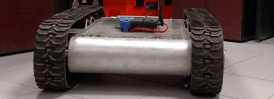
For the implementation of the presented identifier-control scheme, the mathematical model of the HD2® robot is not needed, and the RHONN identifier provides the model. This implementation is achieved by adapting RHONN’s weight vectors using the error between its output and its inputs, which are the measured signal from the robot. For reference, a mathematical model of an all-terrain tracked robot can be found in (Rios et al., 2017), such model is not necessary to design RHONN, however it can be used as a guide.
Test 1: Wireless connection to the all-terrain tracked robot
Test 1 description: The computer that processes the signals and computes the control signal u is connected via wireless communication to the router mounted in the HD2®. The HD2® system sends the information of the measured state variables to the computer using TCP/IP protocol. At the time the controller starts, a command prompt (CMD) window with a ping loop to the HD2® is initialized to record the network behavior with respect to time (Figure 4) in addition to testing the ability of the source computer (the HD2®). A visual representation of Test 1 is presented in Figure 3.

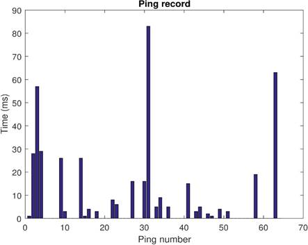
Figure 4: Ping record of Test 1. Ping statistics: Packets: Sent = 64, Received = 64, Lost = 0 (0 % Loss). Approximate round trip in milliseconds: Minimum =0 ms, Maximum =83 ms, Media =6 ms. Please note that in the graphic values of zero represent results of less than 1 ms
Figures 5, 6 and 7 show the comparison of the real measured signals (blue), identified signals (orange) and reference signals (yellow) for position x, position y and position θ, respectively. In these figures, the blue measured real signals are not visible because they are covered by the orange identified signals, visually showing that the errors between them are close to zero. Meanwhile, the errors between the position signals and their references are not zero; however, they are small and bounded.
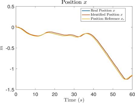
Figure 5: Comparative graph between the measured real position x, the identified
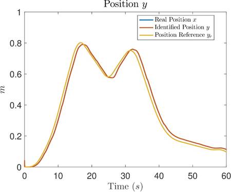
Figure 6: Comparative graph between the measured real position y, the identified
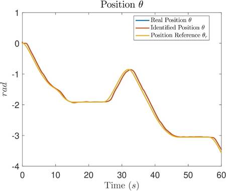
Figure 7: Comparative graph between the measured real position θ, the identified
Table 1 shows the identification root mean square errors (RMSEs) for all state variables of the HD2®. Moreover, Table 2 shows the tracking RMSEs, which are calculated from the identified signals and the reference signals.
Table 1: Identification RMSE of Test 1
| RMSE | |
|---|---|
| Position x | 0.001865 m |
| Position y | 0.001577 m |
| Position θ | 0.005342 rad |
| Velocity v1 | 0.036624 m/s |
| Velocity v2 | 0.038498 m/s |
| Current i1 | 0.131179 A |
| Current i2 | 0.125383 A |
Table 2: Tracking RMSE for Position x, Position y and Position θ of Test 1
| RMSE | |
|---|---|
| Position x | 0.026473 m |
| Position y | 0.030891 m |
| Position θ | 0.072156 rad |
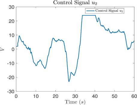
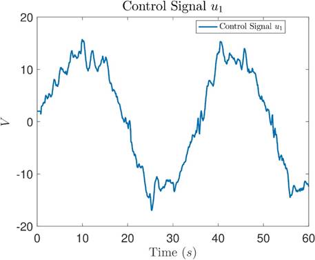
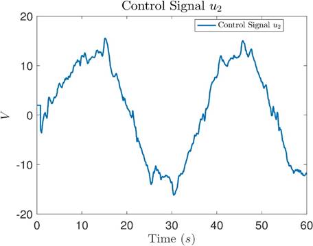
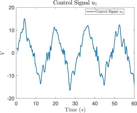
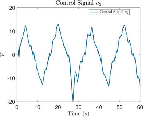
The control signals of Test 1 are shown in Figures 8 and 9.

Test 2: Communication to the all-terrain tank robot through different routers
Test 2 description: The computer that processes the signals and computes the control signal u is connected via wireless communication to a router connected to an inner network. The router mounted in the HD2® is also connected to the same network.
The HD2® system sends the information of the measured stated variables to the computer designated IP address, and the computer responds to the designated IP address for the HD2® using TCP/IP protocol. Similar to Test 1, at the time the controller starts, the CMD window initializes a ping loop to the HD2® to record the behavior of the network with respect to time (Figure 11). A visual representation of Test 2 is presented in Figure 10.

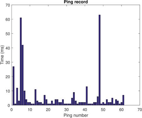
Figure 11: Ping record of Test 2. Ping statistics: Packets: Sent = 61, Received = 61, Lost = 0 (0 % Loss). Approximate round trip in milliseconds: Minimum =1 ms, Maximum =63 ms, Media =6 ms
Figures 12, 13 and 14 show the comparison of real measured signals (blue), identified signals (orange) and reference signals (yellow) for position x, position y and position θ, respectively. In these figures, similar to Test 1, the blue measured real signals are covered by the orange identified signals, showing a close to zero identification error, and the tracking error between position signals and their references is small and bounded.
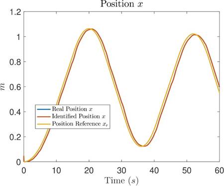
Figure 12: Comparative graph between the measured real position x, the identified

Figure 13: Comparative graph between the measured real position y, the identified
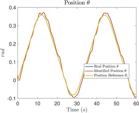
Figure 14: Comparative graph between the measured real position θ, the identified
Table 3 shows the identification RMSEs for all the state variables of the HD2®. Moreover, Table 4 shows the tracking RMSEs, which are calculated from the identified signals and the reference signals.
Table 3: Identification RMSE of Test 2
| RMSE | |
|---|---|
| Position x | 0.002336 m |
| Position y | 0.000807 m |
| Position θ | 0.001393 rad |
| Velocity v1 | 0.034999m/s |
| Velocity v2 | 0.031415 m/s |
| Current i1 | 0.129143 A |
| Current i2 | 0.124773 A |
Table 4: Tracking RMSE for Position x, Position y and Position θ of Test 2
| RMSE | |
|---|---|
| Position x | 0.037489 m |
| Position y | 0.018244 m |
| Position θ | 0.016095 rad |
The control signals of Test 2 are shown in Figures 15 and 16, respectively.
Test 3: Communication to the all-terrain tank robot through different routers
Test 3 description: Test 3 is conducted in the same way as Test 2. The difference between these two tests is the network behavior. This difference can be seen by comparing Figure 11 and Figure 17. It is a fact that the ping loop and the control systems are different programs; however, it has to be noted that they are interacting at the same time with the same devices. Figure 17 shows lost packets, which could be an indicator that in those moments, the network was more stressed.
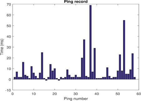
Figure 17: Ping record of Test 3. Ping statistics: Packets: Sent = 58, Received = 56, Lost = 2 (3 % Loss). Approximate round trip in milliseconds: Minimum =1 ms, Maximum =69 ms, Media =8 ms
Figures 18, 19 and 20 show the comparison of real measured signals (blue), identified signals (orange) and reference signals (yellow) for position x, position y and position θ, respectively. In these figures, similar to Tests 1 and 2, the blue measured real signals are covered by the orange identified signals, showing a close to zero identification error, and the tracking error between position signals and their references is small and bounded.
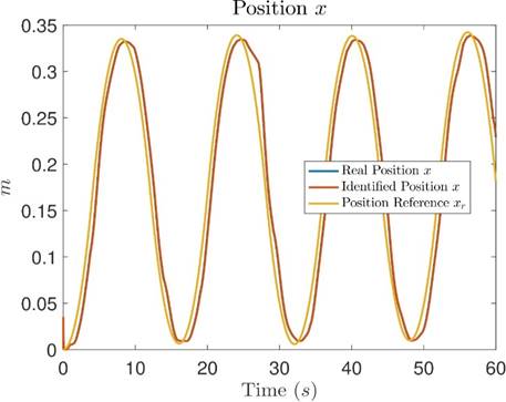
Figure 18: Comparative graph between the measured real position x, the identified
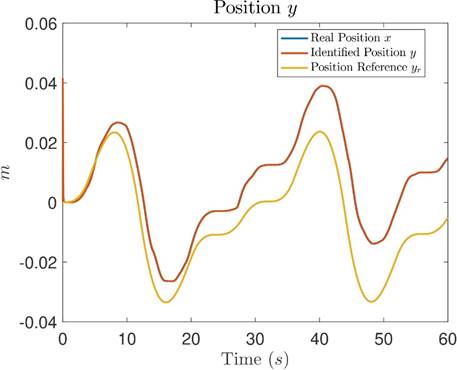
Figure 19: Comparative graph between the measured real position y, the identified
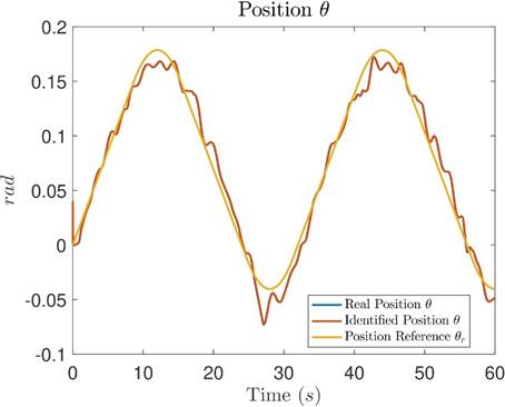
Figure 20: Comparative graph between the measured real position, the identified
Table 5 shows the identification RMSEs for all the state variables of the HD2®. Moreover, Table 6 shows the tracking RMSEs, which are calculated from the identified signals and the reference signals.
Table 5: Identification RMSE of Test 3
| RMSE | |
|---|---|
| Position x | 0.001928 m |
| Position y | 0.000849 m |
| Position θ | 0.001132 rad |
| Velocity v1 | 0.028340 m/s |
| Velocity v2 | 0.028681 m/s |
| Current i1 | 0.130951 A |
| Current i2 | 0.125594 A |
Table 6: Tracking RMSE for Position x, Position y and Position θ of Test 3
| RMSE | |
|---|---|
| Position x | 0.028207 m |
| Position y | 0.013445 m |
| Position θ | 0.011452 rad |
The control signals of Test 3 are shown in Figures 21 and 22, respectively.
Discussion
Results presented in Sections 3.1, 3.2 and 3.3 show the effectiveness of the NIOC for trajectory tracking of unknown discrete-time nonlinear systems subject to uncertainties, disturbances, delays and packet losses, without the need of previous knowledge of models nor bounds. As has been stated in Section 1, there are a lot of similar works reported in literature, however, most of them only have been tested with simulations, results presented in this paper are implemented in real-time for an all-terrain tracked robot controlled using a wireless network with all the communication problems that can be encounter in a real-life scenario. In Villaseñor et al. (2018) it is reported a NIOC for the same kind of system without consider communication problems, then the proposed NOIC represents an improvement of previous results considering communication problems introduced by the network which is a common trouble nowadays.
In this way, intelligent controllers can be a solution to alleviate this kind of problems, in fact fuzzy controllers have been used to deal with control of uncertain nonlinear systems (Aouf et al., 2019; Tong el al., 2020; Pillai & Suthakorn, 2019), however as has been stated in Jiang et al. (2016) neural controllers are better suited to deal with complex control task. Then it is important to remark that the use of RHONN to identify the system to be controlled allow us to use any modern control approach to deal with complex control problems as real-time trajectory tracking, this cannot be done with other intelligent controllers like fuzzy systems (Jiang et al., 2016).
Then in order to perform a fair comparison of the proposed controller with respect to another well-established controller that is designed with a state-space representation, that does not require previous knowledge of the exact mathematical model of the system to be controlled, we implement the real-time trajectory tracking problem for the same robot with super twisting methodology (Rios et al., 2017; Levant, 2011), trajectory tracking results are presented in Table 7. These results are obtained without any network problems due to this methodology do not allow us to handle this kind of problems, this issue has been encountered for the real-time implementation and they are mainly due to the chattering problem associated to sliding mode controllers, besides problems produced by communication networks do not depend of the system state therefore they cannot be compensated by the sliding mode controller. Then, the NIOC represents a better response for the problem considered in this paper.
Table 7: Tracking RMSE for Position x, Position y and Position θ
| RMSE | NIOC | Super Twisting |
|---|---|---|
| Position x | 0.0093 m | 0.03600 m |
| Position y | 0.0069 m | 0.08505 m |
| Position θ | 0.0056 rad | 0.0103 rad |
This paper only considers uncertainties, disturbances, delays, and packet losses, while CPS have a lot of problems that are not considered here as: Saturation, hysteresis, backlash, friction, intrusions, attacks, faults and many others, all of them requires attention individually and as a whole system, therefore all this issues can be considered as future work, as well as implementation issues that require our attention in order to reduce time and cost for real-time applications.
Conclusion
This work presents the designing and implementation of an intelligent controller to solve on-line trajectory tracking problem of a mobile robotic system in a wireless networked environment. It is important to note, that the tests presented in this work show the performance of the NIOC scheme applied to a HD2® all-terrain robot for different network conditions, first in a direct wireless communication channel, and then, in a wireless environment with two networks. Real-time results, show that the identification performance presents errors close to zero and that the tracking performance presents small and bounded errors despite uncertainties, unknown dynamics, delays and packet losses. It is important to note that results are obtained without knowledge of the mathematical model of the HD2®, which is based on the RHONN identifier model; the control is calculated using the neural network model. In this way, the tests show how the NIOC scheme is presented as a good candidate for its robustness against unknown dynamics, unknown external and internal disturbances, unknown communication delays and packet losses.

