


 nueva página del texto (beta)
 Inglés (pdf)
 Artículo en XML
 Referencias del artículo
 Enviar artículo por email
 Citado por SciELO
  Similares en
SciELO
Similares en
SciELO 
 Permalink
Introduction
Vibration and shock isolation are usually achieved by using flexible supports and/or increasing the effective system mass in order to reduce the natural frequency of the isolated item. In the particular case of shock isolation, its transient nature poses a further challenge due to the short duration and usually high amplitudes involved. Nonlinearities can also occur due to the high deformations in the elastic element. Ideally, a shock isolation mount should have a low stiffness during the shock but must be stiff enough to support loads, that deforms it in the elastic zone, when no impact excitation is present. Preferably lightly damped, although damping is necessary to quickly dissipate residual free vibration, as presented by Nelson in 1996.
Recent research in this direction considers different stiffness strategies. The use of nonlinear cubic stiffness (i.e. Duffing isolator) has been studied theoretically by Tang and Brennan (2014) and Liu et al. (2014). These studies demonstrated that the use of cubic nonlinearities in the stiffness is advantageous for reducing absolute acceleration and displacement responses in shock excitation, with a detrimental effect on relative motion. Their findings have been validated experimentally by means of a mechanically suspended permanent magnet located between two electromagnets by Ledezma et al. (2015). By changing the intensity and polarity of the voltage supplied a nonlinear stiffness effect is achieved.
On the other hand, it is possible to improve isolation efficiency at higher frequencies using passive linear elements using a two-stage mount, which is a two-degree of freedom model. When using this intermediate mass system, transmissibility at high frequency rolls off at 80 dB/decade compared to 40 dB/decade for an undamped single degree of freedom system. However, the inconvenience of adding a second stage is evident as the total mass of the system might increase. Even if it is possible to keep the total mass and divide it into two stages, the space or clearance required is increased. Moreover, a two-stage system adds a second resonance, which justifies its use only when high-frequency vibration is a concern.
Although two-stage mounts are well documented and have been applied in practice for many years (Rivin, 2003), their shock isolation properties and response are not properly documented. Snowdon and Parfitt (1959)studied the response of the two-stage mount under an acceleration step. Findings suggested that a large secondary mass leads to a reduced acceleration, while damping does not affect the response as it does on an equally damped simple mount. According to the authors, this is the only study concerned with shock isolation considering a linear two-stage mount, which is limited only to a step excitation and uniform damping. Shekhar et al. (1999)revisited the two-stage mount considering linear spring elements and nonlinear cubic damping. Their finding assumed that nonlinear damping in the primary system leads to better isolation in terms of absolute acceleration, displacement, and relative motion.
In contrast, the response to harmonic inputs considering nonlinear elements in the two-stage mount has been considered in different aspects. For example, Zhu et al. (2004) studied a combination of quadratic damping and cubic stiffness. Their findings suggested that low vibration response could be obtained by adjusting the secondary nonlinear stiffness and damping. Gatti et al. (2010) investigated the analytical response of a two-degree of freedom system where the main stage is a linear oscillator with a nonlinear attachment that has quasi-zero stiffness modelled by cubic nonlinearity.
Research work developed by Lu et al. (2014) analysed a two-stage isolator with hardening nonlinearity and viscous damping. Overall, force and displacement transmissibility are improved in the nonlinear isolator compared to the linear system. Furthermore, Lu et al. (2013) also investigated the effect of nonlinearity in the first, second, and both stages. Their findings suggested that the best combination in terms of isolation is to have nonlinearity in the second stage with high damping, while the first stage is linear and lightly damped. Lu et al. (2017) also developed theoretical studies using bi-stable plates. Their findings assumed an improvement in displacement transmissibility compared with the linear isolator.
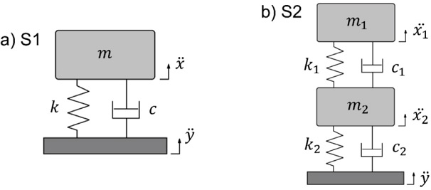
Wang et al. (2017) also found that high damping in the nonlinear second stage and a large intermediate mass attached to a soft spring in the first linear stage is beneficial. According with previous research work the shock isolation properties of the two-stage mount have not been properly documented nor theoretically or experimentally. As a result, this paper aims to present a novel contribution on a known system, performing an analysis of the shock response of the two-stage mount. Obtained results will be compared with the classical single-degree-of-freedom (SDOF) model, as presented in Figure 1 below where the two models considered are depicted (Harris & Piersol, 2002). The isolation properties are discussed, highlighting the advantages and disadvantages of each model studied. Experimental validation is also presented, where a simple two-stage isolation model is tested under harmonic excitation and shock pulses of different durations, analysing the effect of the mass ratio. Because response depends on mass ratio, first stage mass can be reduced when adding the second stage.
Background
The standard approach for predicting the shock response of a linear system is to consider a pulse function as an external signal excitation. Different types of signal can be employed for this case of study, such as: a half sine, versed sine, rectangular, triangular, or another pulse function. And also, evaluating a particular response parameter as a function of the relative duration of the shock. The duration of the pulse and the natural period of the system are related by the period ratio τ T , where τ is defined as the shock duration and T is the natural period of the system. The equation of motion of system S1 is:
And will be subjected to a versed sine acceleration pulse
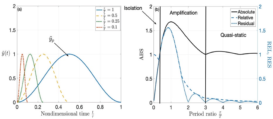
Figure 2: a) Versed sine pulse for different durations, b) shock response
spectra corresponding to a SDOF system under a half sine pulse
acceleration input of maximum amplitude yp. Responses are
normalised considering the maximum acceleration amplitude and its
resulting input displacement,
The response of the system is usually separated in two-stage, namely the forced
response during the input, and the subsequent free, or residual vibration. The Shock
Response Spectra (SRS) is a representation of the non-dimensional response, as a
function of the period ratio
Shock response of linear two-stage isolator
Mathematical model
Consider a two-stage system S2 as depicted in Figure 1b. The mass ratio μ is defined as a relationship between the additional stage mass m2 and the isolated mass m1. Each isolation stage has a combination of stiffness k1, k2, and viscous dampers c1, c2 respectively.
Where 𝑧 represents relative motion defined by z1 = x1 - y and z2= x2- y
Introducing the parameters,
Where
Effect of mass ratio over SRS
The shock response spectra for absolute acceleration and relative motion are
showed in Figure 3, comparing the isolation
properties of the single mount S1 and the two-stage mount S2. Figure 3a resents absolute acceleration and
Figure 3b is for relative motion. Mass
ratio cases studied are μ=0.2, μ=1, μ=2, and μ=5. For all cases, damping is
considered to be light and proportional, i.e. 1 % of the critical value for both
stages. For the case when the secondary stage mass m2 is a fraction
of the main mass m1, 20 % in the example considered, a small
reduction in absolute response is observed for very short pulses, up to the
maximum response zone, i.e. approximately
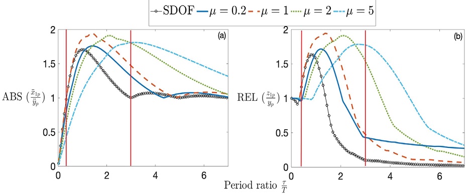
Figure 3: Shock response spectra for the two-stage mount S2 compared with
the single mount S1, for different values of the mass ratio, a)
absolute acceleration response
Furthermore, consider now Figure 4, which
shows time histories for period ratios of
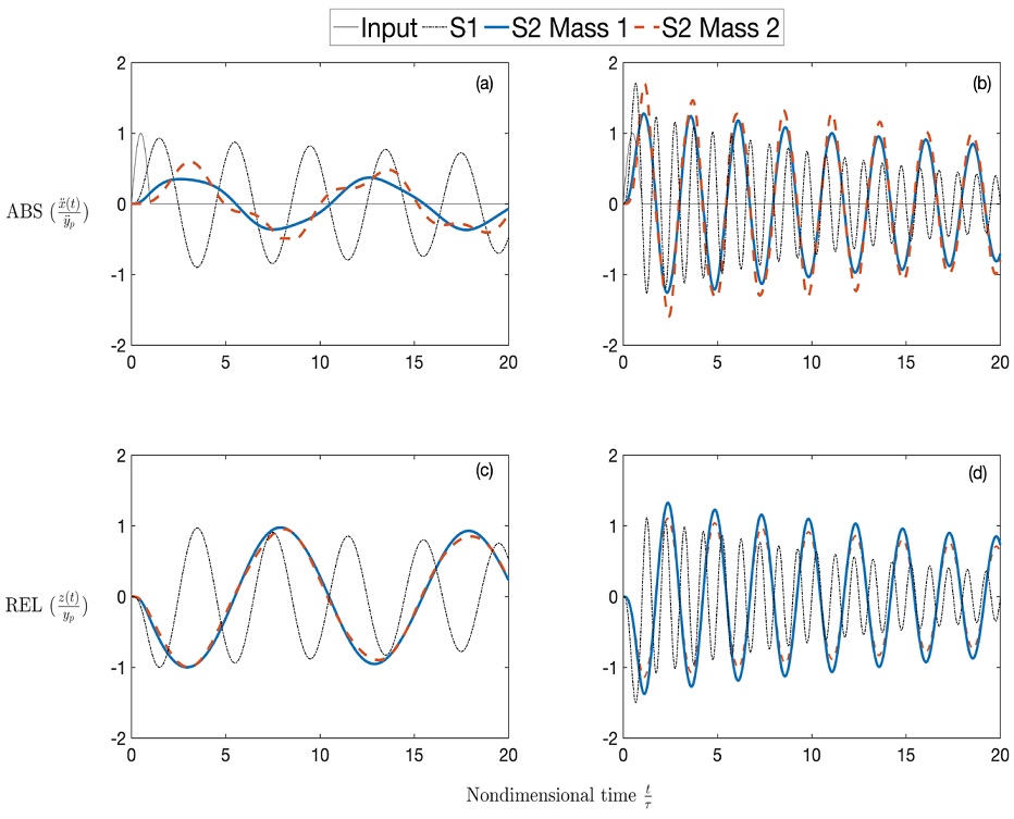
Nevertheless, these advantages of the two-stage mount imply a larger space is
required for the additional mass and stiffness element and are justifiable only
if a large mass ratio is allowed, even if the total mass is kept constant and
divided between the two stages. This can be particularly beneficial for short
impacts as their frequency content is higher. The benefits are then similar to
those observed in harmonic excitations where the high-frequency isolation
performance is increased when using a two-stage mount. When
A further insight into the effect of the mass ratio can be obtained by analysing the response contribution from each stage in the isolation system. As shown in Figure 5.
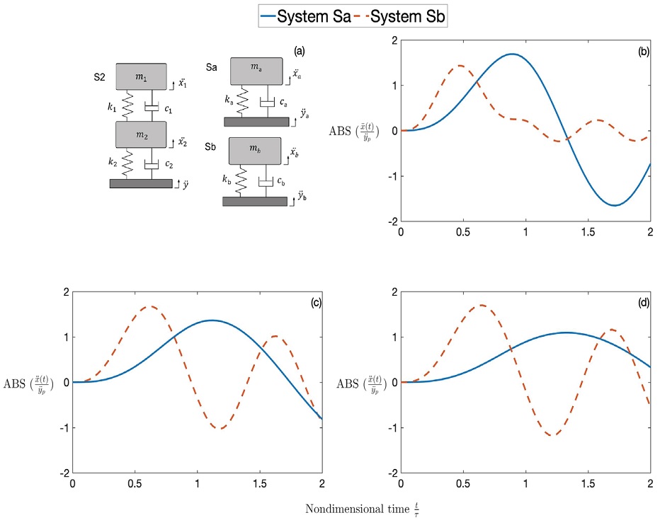
Figure 5: Absolute acceleration response
Using the orthogonality properties of the mass and stiffness matrices of the system with the modal matrices, it is possible to decompose the 2 degree of freedom system into two equivalent single degree of freedom systems. This analysis is well known in structural dynamics and it is performed by solving an eigenvalue problem where the frequencies and mode shapes of the system are found. Then a linear transformation is applied using the orthogonality of the matrices to obtain the diagonal matrices of the decomposed system in a new set of modal coordinates. As a result, the two resulting systems can be analysed independently and their contributions added to find the global response using the linear superposition principle. It is beyond the scope of this paper to discuss the process as it is well known, but the reader can refer to the comprehensive book of He and Fu (2001) for further information.
Figure 5 presents the modal decomposition
of system S2 for
Effect of viscous damping
The effect of adding viscous damping in the two stages is analyzed in this section. Three cases have been studied in order to find the optimum scenario in terms of isolation:
Damping added to the secondary stage.
Damping added to the primary stage, and finally.
Damping added to both stages.
Figure 6 shows results of the shock response spectra for the three scenarios studied considering a mass ratio of μ=5 since with this value it is possible to obtain appreciable improvements in the shock response. The obtained response is compared with a viscous damping in a single mount. The values of damping percentage studied were: 1 %, 10 % and 30 %, which are values of common commercial isolators. For the case of the effect of damping on the secondary stage (Figure 6a) compared to the single mount, results suggested that increasing the damping further enhances the isolation in the two-stage mount around the amplification region, but below a period ratio of 1. The actual difference of response as a function of damping is marginal. After this period ratio, the addition of damping helps to reduce the absolute response, but it is still higher compared to the one with a single mount. In contrast, for the case of adding damping on the primary stage (Figure 6b) results showed almost no difference. Consequently, for the case of the adding of damping in both stages, results (Figure 6c) showed a similar behavior to the case of damping on the secondary stage. Figure 6d shows the relative response considering damping on the secondary stage, demonstrating a reduction of relative motion during amplification. However, the response does not change for very short pulses regardless of damping. By comparing the undamped systems presented in Figure 6, it easily confirmed that the response of the two-stage mount is much smaller compared to the single mount. When adding damping, the benefit is smaller compared with the single mount. As it was stated before, the effect of damping is small for short pulses. However, the benefit of adding damping in the primary mass is a quick suppression of the residual vibration.
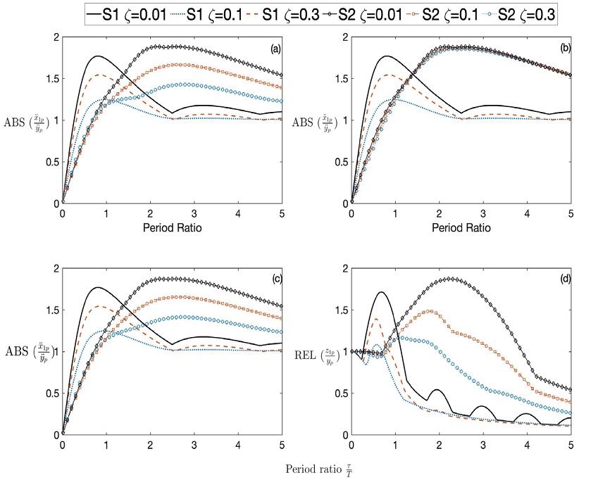
Figure 6: Shock response spectra of absolute acceleration
Experimental validation
In this section, experimental validation of the vibration and shock isolation of the two-stage mount is presented. A simple experimental rig was performed, employing two commercially available helical spring isolators of the same characteristics. Each spring has a mass of 268 grams, and a stiffness constant of 43 N/mm. For the reference single-stage mount, referred as case A, a mass of 1.2 kg was employed. Then, the two-stage mount was assembled with secondary mass of 1.7 kg, 3.4 kg, and 5.1 kg resulting in mass ratios of μ=1.41, μ=2.83 and μ=4.25. These values were chosen based on availability and to keep the system stable for lateral vibrations. Only the inherent internal and structural damping of the springs is considered, and its effect is not studied since the damping is considered light for engineering purposes (less than 5 % of critical damping as presented later). The isolation systems were mounted on a LDS V721 electrodynamic shaker, for vibration transmissibility and shock response testing. Acceleration was monitored on the shaker base and on the masses with PCB accelerometers of 100 mV/g. The signals were recorded in a LDS LASER USB vibration controller. Figure 7a presents a schematic diagram of the experimental test set-up, while Figure 7b shows the experimental-laboratory test rig.
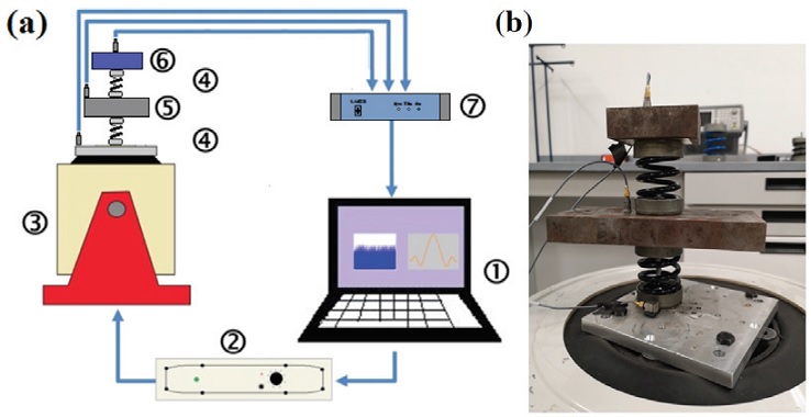
Figure 7: Experimental test setup used on the transmissibility and shock response measurements, a) shematic diagram of the complete system, b) the two-stage isolation system laboratory test rig (1. PC, 2. Amplifier, 3. LDS V721 Shaker, 4. Helical springs, 5. Secondary mass, 6. Main mass, 7. Shaker control system)
Two different set of tests were performed. First, vibration transmissibility was measured using a broadband excitation from 5 to 200 Hz. This is common practice in vibration testing in order to excite all the natural frequencies within the frequency band of interest (Harris & Piersol, 2002; He & Fu, 2001). Shock response was measured considering a displacement compensated half sine acceleration pulse applied to the base. The amplitude of the pulse was kept constant at 1g, and the pulse durations were 5 ms, 10 ms and 20 ms. Pulse durations were selected considering pulses around the natural periods of the mounts, and the physical limits of the testing facilities. These pulse durations result in approximate period ratios of 0.135, 0.25, and 0.5, comparable with short duration pulses where the differences between the single and the two stage mount are easier to appreciate. Figure 8 shows the experimental transmissibility of the single and two-stage mount, compared with the theoretical curve. The well-known effect of isolation improvement at higher frequencies is easily observed, which is better as the secondary mass increases. The natural frequencies values measured and damping ratios calculated using the half bandwidth method for each corresponding resonance peaks are presented in Table 1.
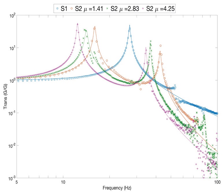
Figure 8: Absolute transmissibility of the two stage mount S2 considering different mass ratios, and the single stage mount S1. The lines represent the theoretical curves whilst the markers represent the experimental result for the different cases
Table 1: Values of natural frequencies and damping ratios for the studied mounts
| System | Natural frequencies (Hz) | Viscous damping ratio |
| Single stage S1 | 27 | 0.017 |
| Two stage S2 μ=1.41, | 16, 43 | 0.017, 0.005 |
| Two stage S2 μ=2.83 | 13, 37 | 0.015, 0.007 |
| Two stage S2 μ=4.25. | 12, 34 | 0.013, 0.007 |
Results of the shock response are presented in Figure 9. In this case, the response of the different mounts is compared with the single mount (Figure 9a), and the two-stage mount with the three mass ratios studied i.e. 1.41, 2.83 and 4.25 (Figures 9b, 9c and 9d, respectively). The curves on each figure represent the different pulse durations of 5 ms for the continuous line, 10 ms for the dashed line, and 20 ms for the dotted line.
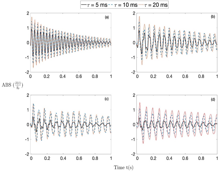
Figure 9: Experimental acceleration time response
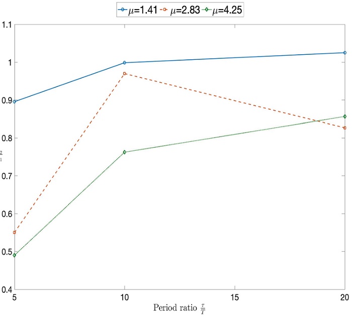
Comparing the response of the different two-stage systems with the single-stage mount in Figure 9, it is concluded that the main reductions in the absolute shock response while not increasing relative motion, was obtained for the case of the shorter pulse of 5 ms. In terms of maximum amplitude the response obtained of the two-stage mount with mass ratio of 1.41 is very similar to the response obtained by the single-mount. However, a reduction in maximum shock response begins to be noticeable for the case C in the Figure 9c with a mass ratio of 2.83. There are some marginal improvements for the longer pulses of 10 ms and 20 ms in the same system. Furthermore, higher response reductions were obtained for the larger mass ratio of 4.25, where the maximum response for the 5 ms pulse is greatly reduced. For a quantitative analysis, the response of the different systems can be easily compared by considering the natural period of the single-stage system as a reference T=37s. The maximum response of the two-stage mount compared to the maximum of the single-stage is presented in Figure 10, for the different cases. In this graph, the horizontal axis represents the ratio between the shock duration and the natural period of the single-mount. It is evident that when the masses are equal, the benefits are small for the case of short pulses compared to the natural period of the reference system. The response is even amplified for longer pulses. As the secondary mass increases, the reduction in maximum response is greater and although better for short pulses, there are still some benefits in longer pulses. These effects were also observed in the theory, especially on Figure d, where the theoretical SRS demonstrates that isolation is improved for shorter pulses up to the amplification region. However, in the case of lower secondary masses the benefits are not evident and the response can be even amplified. It can be concluded that although the benefits of a second mass are achievable and significant, it is only justifiable when volume requirements and weight is not an issue. Since for shock isolation, the secondary mass needs to be at least three times greater than the main mass to provide better shock isolation.
The analysis presented in this paper reflects the validation of a theoretical model, including its shock response showing that it is possible to reduce acceleration response while maintaining relative motion, by using a two DOF mount. The experimental validation was performed with a simple model trying to be as closest as possible to the mathematical model. Further research is recommended to include important effects of actual isolators such as nonlinear phenomena and the implement of a practical realization of a shock absorber with two stages, such as the twin absorber presented by Jadhav et al. (2012).
Conclusions
Two-stage isolation mounts are well known for its improved high frequency isolation in harmonic and random vibration, at the disadvantage of adding a second resonance and increased mass, however, their shock response and isolation properties are not well documented. This paper presented a theoretical and experimental study of the shock response and isolation of a two-stage isolation mount, which was compared with a single-stage mount. The effect of mass ratio and viscous damping was analysed. The theoretical analysis considered the response under an ideal base acceleration pulse of different durations, and the shock response was quantified. It was found that adding a large secondary mass compared to the main mass improves the system reducing the absolute shock response, with the disadvantage of potentially increasing the mass and volume. This effect is only significant as long as the secondary mass is at least five times greater than the main mass for the case of short pulses compared to the fundamental natural period of the system. The experimental validation was performed using two commercial isolator and different masses. Experimental results obtained demonstrated the theoretical findings. Improvements were obtained in terms of shock isolation for the case of short pulses when the secondary mass is larger than the main mass while maintaining the same relative motion when compared to the single mount. It can be concluded that the benefits of using a two-stage mount are justifiable when there are no volume and weight restrictions. Further research work in this direction is recommended in order to investigate the use of nonlinear springs in a two-stage mount that might help to reduce the weight of the isolation system.

