


 nueva página del texto (beta)
 Inglés (pdf)
 Artículo en XML
 Referencias del artículo
 Enviar artículo por email
 Citado por SciELO
  Similares en
SciELO
Similares en
SciELO 
 Permalink
Introduction
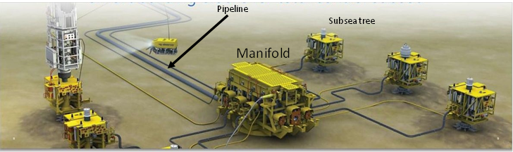
Oil and gas exploitation in deep water sites required the installation of offshore infrastructure that usually consists of floating production systems (floaters) and subsea systems. Subsea production systems are all the components that permit to explode hydrocarbons, which are installed on the sea floor. They are commonly composed by the all the equipment, flow lines and accessories that allow the hydrocarbon exploitation. The main subsea systems are: manifolds, pipeline end termination (PLET), pipeline end manifold (PLEM) and umbilical termination assembly (UTA). Figure 1 shows a typical subsea system deployment that includes a manifold.
Subsea systems required a foundation system in order to be anchored into the marine soil deposits and suction caissons represent a pragmatic option (Figure 2a). There are well-documented references that report the extensively use of suction caissons in floaters and subsea systems (Andersen et al., 2005; Valle et al., 2008; Silva et al., 2013; Foresi & Bughi, 2015; Kay, 2015).
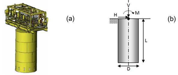
Figure 2 a) Manifold and suction caisson (Palix et al., 2010), b) geometry of the suction caisson and loading applied at the head
One of the main relative benefits for using suction caissons is the shorter timing required for their installation in comparison with other options such as driven piles. In addition, suction caissons are easier to be positioned in production areas with limited space since there are dense number of infrastructure. Finally, they could be used in a wide range of water depth.
Suction caissons are large diameter cylinders typically made with steel ranging from 3m to 20m with aspect ratios (L/D) varying from 0.5 to 6 (Kay, 2015). They are also denominated in the industry as suction piles or suction anchors; the portion of the name “suction” came from the installation process of this type of foundations, which consists in two steps:
Evaluations of the capacity of the foundation are required to ensure the stability of subsea systems, in the case of subsea systems, the foundations are subjected to combined, general or multiaxial loading, which consists in applying combinations of horizontal and vertical loading (H,V) with driving moments (M) as seen in Figure 2b. Loads on subsea foundations are generated by self-weight, thermal expansion of attached pipelines or other actions of the equipment connected (Gouvernec & Feng, 2014). Thus, the stability and safety of the subsea system depends directly on estimating the failure or yield surface for different loading and moment combinations (VHM).
The idea of obtaining failure envelopes or yield surfaces was adopted from early works by Roscoe & Schofield, (1957), and the application to design offshore foundations was one of the main triggers for calculating different VHM capacity surfaces (Salgado et al., 2008). The use of failure envelopes permits to evaluate the interaction of horizontal, vertical and moment load in an integrated manner.
This work addresses a study of the combined capacity of suction caissons by means of numerical modeling using finite element method. Numerical analyses were executed for short-term conditions of the soil (undrained scenario) and the caisson is assumed as “wished-in-place”; thus, no effects of installation process are considered.
Background
Failure envelopes for combined capacity of suction caissons
Failure envelopes or yield surfaces represent the boundary of the combination of loading that the pile-soil can withstand. The failure envelopes for suction caissons under multiaxial loading (VHM) reported by Kay & Palix (2010) and Kay (2015) have exhibited elliptical shapes in the MH plane and a “thong-shape” failure envelope in the VHM space, as presented in Figures 3a and 3b, respectively. The envelopes were obtained through numerical modeling of suction caissons in offshore clay with aspect ratios (L/D) greater than 1.5 and general loading applied at the caisson head.
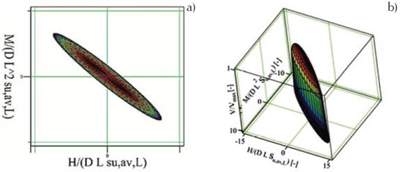
Figure 3 Failure envelopes for suction caisson subjected to combined loading at the caisson head: a) envelope in the MH plane, b) VHM envelope for caissons with ratio L/D>1.5 (Kay, 2015)
Mechanisms of failure for suction caissons under combined loading
Former studies of suction caissons subjected to lateral loading applied at the caisson head have reported that the type of mechanism or mode of failure depends directly on the aspect ratio of the caisson. Caissons with short aspect ratios (L/D>1) develop active and passive wedges along the caisson shaft and circular shear planes inside de caisson, as seen in Figure 4a (Kennedy et al., 2015); this type of failure is denoted as short-caisson mechanism.

Figure 4 Mechanisms of failure of the suction caissons under lateral loading at the top: a) short-caisson mechanism (L/D>1), b) flow-around mode and c) external-scoop mechanism (Kennedy et al., 2015)
Caissons with slightly larger aspect ratios, which are also subjected to horizontal load at the top fail with the flow-around mechanism (Figure 4b). This type of failure is similar to the short-caisson mode but the wedges do not extend to the base of the caisson.
Moreover, caissons with greater aspect ratio and lateral loading applied at the top exhibit clockwise rotation of the whole caisson (if horizontal load is applied from right to left direction) and wedges along the upper zone of the caisson (Figure 4c). This type of mechanism is denoted as external-scoop, which usually has the following unknown parameters: the position of the center of rotation, the size of radius of the rotational zone of failure and the distance of the wedges between the mud line and the center of rotation.
On the other hand, Figure 5 shows the adjusted H*M* capacity envelope for combined loading and the corresponding failure modes reported by Palix et al. (2010). H* is the adjusted lateral capacity defined by
As seen in Figure 5, the mechanisms of failure also depend on the directions of the loading and moment applied. Horizontal loading form left to right direction, vertical compression load and moments in clockwise direction are considered positive sign. This sign convention was also adopted in this research.

Figure 5 Failure modes of a suction caisson (L/D=1) under combined loading at the top (Palix et al., 2010)
The results in the first quadrant (H* and M* positives) and fourth quadrant (H* positive and M* negative) are presented in Figure 5. In the first quadrant, the modes of failure under pure moment and pure horizontal loading exhibit the external-scoop mechanism.
Otherwise, the mechanism for combined loading in the fourth quadrant under horizontal load H* nearby to 9 and M* of about 6 exhibits a clear translational failure, while a rotational failure of the whole caisson is observed for the combination M* of about 5 and H* equal to 6.
Axial capacity
Calculation of the axial vertical capacity (compressional or tensional) of a suction caisson may involve the use of alpha method (α) that considers the shaft and tip capacity components. The alpha method is also known as the API method and has been extensively used to design offshore driven piles. This method was conceived in terms of total stresses and was calibrated by Randolph & Murphy (1985). The portion of the shaft capacity or skin friction of the caissons is expressed as follows:
where:
For normally consolidated clays, α is usually near to 1.0, more precisely in the range from 0.8 to 1 (Randolph & Gouvernec, 2011). El-Sherbiny (1999) found from four tests in a 1-g physical scale model of suction caissons installed in kaolinite that an average α of 0.78 was mobilized at the failure load. Also, results of a 1-g physical model that mimic piles of fixed platforms installed in clayey soil of the Campeche Bay offshore Mexico indicate that alpha was equal to 0.83 (Rufiar et al., 2011). In contrast, α ranges from 0.4 to 0.6 if soil exhibit high values of overconsolidation ratio (OCR) as reported by Randolph & Gouvernec (2011).
Regarding the vertical capacity in compression and extension at the tip, this portion of the axial capacity can be estimated as:
where Atip is the area of the caisson tip and Nc is the end bearing capacity factor, which has been reported typically equal to 9 in compression loading (Randolph & Gouvernec, 2011). The factor Nc for vertical pullout has been suggested equal to 7 for suction caissons by Clukey & Morris (1993). However, other model tests have reported similar values of Nc= 9 no matter if the vertical failure occurs in compression or extension. Nevertheless, it is important to note that in the numerical model of this research only the shaft portion of the axial capacity is reproduced through the interface elements by means of the adherence factor.
Geotechnical conditions of the deep Gulf of Mexico
Typical soils in deep water sites of the Gulf of Mexico consist in normally consolidated fine soils with linear variation of the undrained shear strength Su with depth (Yun et al., 2006; Randolph & Gouvernec, 2011). Kay & Palix (2010) defined three possible undrained shear profiles to cover the offshore conditions: a) constant value of Su, b) linear variation of with depth Su and c) stepped Su profile. In this study, the constant profile were considered exclusively to verify the results of the model, while the results correspond to a caisson in soil with the linear variation of Su as 1.25z (kPa) where z is the depth in meters. In other words, this work pursues to estimate and study the combined capacity of caisson in geotechnical conditions of the deep Gulf of Mexico.
Numerical models
The suction caissons models have a diameter of 5 m and length equal to 7.5 m (L/D= 1.5) and 15 m (L/D= 3). They are steel made with Young´s modulus of 2.1 x 10⁸ kPa and Poisson´s ratio equals to 0.3. The thicknesses of the caisson walls are 3.5 cm and the cap equal to 5 cm. The model with bigger aspect ratio was used to compare and verify the results by comparing them with numerical data reported by Palix et al. (2010).
The caisson-soil system was represented by a cylindrical mesh formed by concentric elements, which are divided in radial and angular units, as shown in Figure 6. Also, the three-dimensional mesh presented in Figure 6a could be split in two parts taking advantage of the symmetry of the model, in order to optimize the computation timing during the analyses.
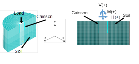
Figure 6 Finite element mesh of caisson-soil system under combined loading: a) half of the 3D cylindrical mesh and the model of the suction caisson, b) caisson-soil model and the combined forces and moment applied
The boundary conditions consider:
Fixed nodes located at the bottom of the model that restricts the displacements in vertical direction of the mesh.
The nodes along the perimeter of the cylindrical mesh (border side) are restricted to move in horizontal direction.
The top side of the mesh includes elements with nodes, which are free to move in all directions.
Nodes in the plane of symmetry are restrained from displacements in the normal direction.
The suction caisson and the soil deposit were modeled using ANSYS® SOLID45 eight-node brick and prism elements. Point-to-surface elements were considered for the external and internal soil-caisson interfaces along the caisson shaft, while surface-to-surface elements were used for representing the head and tip of the caisson. The adherence factor or side shear factor (α), used to evaluate shaft capacity portion of the axial capacity of piles, is considered in the interface elements along the wall of the caisson to reproduce the frictional shaft capacity. The Von Mises yield surface was used in the model with no dilation and undrained conditions. The undrained shear strength profile considered varies linearly with depth. The loading applied at the head of the caisson and the convention of the direction considered are shown in Figure 6b.
Results of the FEM were compared with similar results reported by Palix et al. (2010) using the program Plaxis 3D® for a caisson model with 5m diameter and 3m long (L/D = 3), and considering a clayey soil profile with undrained shear strength of 10 kPa constant with depth and side shear factor α= 0.65. They consider also the ratio E/Su of 500 and unit weight of the soil equal to 5 kN/m3. As seen in Figure 7, the horizontal component of capacity varies from 0 to about 8 MN, while the moment ranges from -27 MN-m to 27 MN-m. It can be seen that the envelop exhibits an ellipsoid shape, despite that only information of the first and fourth quadrant are shown (positive values of the horizontal capacity).

Figure 7 Comparisons of the results finite element results between this study and reported values (Gomez, 2014)
It is evident that the FEM results of ANSYS meet very well with Plaxis 3D results. The values obtained with the ANSYS model were always greater than the results reported by Palix et al. (2010). The differences between the results ranges from 5% to 14%.
Results
In this section, the numerical results of the suction caisson with 5 m of diameter and 7.5 m of length (L/D= 1.5) subjected to combined loading are presented. The model of the caisson considers the mechanical properties of steel with similar values of the parameters presented in Section 3. The soil deposit considered exhibits a linear variation of the undrained shear strength Su given by a value of 0 kPa at the mud line and a gradient of 1.25 (kPa/m) was employed. The ratio E/Su of 500, unit weight of the soil equal to 5 kN/m3 and Poisson´s ratio of the soil equal to 0.49. The first part of the results covers the curves of force and moment varying with displacement and angle of rotation, respectively; and the mechanisms of failure of the caisson. The second part includes the failure envelopes obtained in this study.
Combined caisson capacity
Evaluations of the capacity of the suction caissons, under combined loading applied at the top were obtained through the results of the FE analyses by means of curves of loading varying with displacements and moment changing with rotation angles. The failure criteria for the caisson-soil system subjected to lateral and vertical loading was defined when the displacement reached 10 percent of the caisson diameter. For the rotational capacity, the moment of failure was selected as the curve exhibits asymptotical tendency.
Figures 8a and 8b depict the load-displacement curves for horizontal and axial loading, respectively. In addition, Figure 8c shows the driving moment varying with the angle of rotation in degrees. The curves present also the variations of the capacity with the adhesion factor (α) ranging from 0.5 to 1. It is evident that the curves and capacity increase as augments α and the curves exhibit clear asymptotic tendency for lateral loading and pure driving moment. The moment of failure was well identified beyond about an angle of 1°, which is consistent with the results presented by Chen et al. (2015).

Figure 8 Variation of loading with displacements and driving moment with angle of rotation: a) axial loading, b) horizontal loading and c) driving moment
Figure 9 shows the mechanism of failure for pure horizontal loading and the different regions of failure that surround the caisson, which corresponds clearly to the external scoop type. The components of the external scoop mode are identified in Figure 9a. In addition, Figures 9b and c show the external scoop mechanisms obtained for shear factor (α) of 0.5 and 1, respectively.
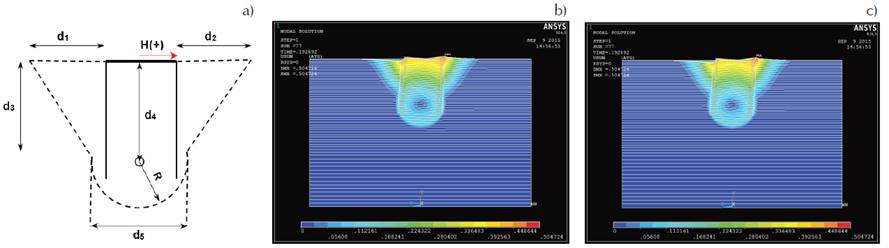
Figure 9 Mechanism of failure of the suction caissons under horizontal loading at the top: a) parts of the mechanism, b) external-scoop mechanism for soil with α = 0.5, c) external-scoop mechanism for soil with α = 1
The dimensions of the different components of the failure regions varying with the adhesion factor are presented in Table 1. As seen, each soil wedge extend horizontally at the sea floor up to one diameter (D) and reach a depth of about also one diameter (D). The center of the radius of the rotation failure at the caisson tip is located in the caisson at a depth of about1.2 D. The radius of rotation of the caisson-soil system is about half of the diameter.
Table 1 Dimensions of the components of the mechanism of failure of the caisson-soil system under lateral loading
| α | R | d1 | d2 | d3 | d4 | d5 |
|---|---|---|---|---|---|---|
| Adimensional | m | m | m | m | m | m |
| 0.50 | 0.585D | 1.025D | 1.025D | 0.98D | 1.200D | 1.325D |
| 0.65 | 0.585D | 1.025D | 1.025D | 0.98D | 1.200D | 1.350D |
| 0.80 | 0.585D | 1.05D | 1.025D | 0.937D | 1.195D | 1.375D |
| 0.90 | 0.633D | 1.05D | 1.025D | 0.937D | 1.195D | 1.375D |
| 1.00 | 0.633D | 1.05D | 1.025D | 0.937D | 1.195D | 1.375D |
Note: D is the diameter of the caisson
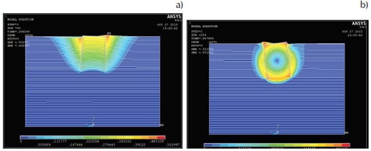
In addition, Figure 10 depicts the mode of failure of the caisson-soil system under pure positive moment (applied in clockwise direction). The failure mechanism identified corresponds also to the external-scoop type. Sizes of the different components of the failure zone varying with the adhesion factor are presented in Table 2. In this case, soil wedges extend horizontally up to 0.8 D along the sea floor level and reach a depth of about 0.8 D. The center of the radius of the rotation failure at the caisson tip is located in the caisson at a depth of about1.2 D. The radius of rotation of the caisson-soil system is about half of the diameter (0.5 D).

Figure 10 Mechanism of failure of the suction caissons under pure clockwise driving moment at the caisson head: a) parts of the mechanism, b) external-scoop mechanism for soil with α = 0.5, c) external-scoop mechanism for soil with α = 1
Table 2 Dimensions of the components of the mechanism of failure of the caisson-soil system under pure positive moment
| α | R | d1 | d2 | d3 | d4 | d5 |
|---|---|---|---|---|---|---|
| Adimensional | m | m | m | m | m | m |
| 0.50 | 0.73D | 0.80D | 0.78D | 0.80D | 1.10D | 1.52D |
| 0.65 | 0.73D | 0.80D | 0.78D | 0.80D | 1.08D | 1.50D |
| 0.80 | 0.76D | 0.80D | 0.77D | 0.75D | 1.08D | 1.55D |
| 0.90 | 0.76D | 0.80D | 0.77D | 0.73D | 1.08D | 1.55D |
| 1.00 | 0.77D | 0.79D | 0.77D | 0.70D | 1.07D | 1.55D |
Note: D is the diameter of the caisson
Moreover, Figure 11a shows the mode of failure of the caisson-soil system under the combination of negative moment M=-10206 kN-m (moment in counterclockwise direction) and lateral force H = 2041 kN, which gives a ratio M/H=5. The mechanism of failure correspond to a translational mode slightly rotated with clockwise orientation. In contrast, the clear counterclockwise rotational manner of failing of the caisson-soil system under the simultaneous application of a negative moment M=-10179 kN-m and H = 1272 kN (M/H=8) is observed in Figure 11b. The failure mechanisms found in this work of combined loading with negative moments and positive lateral loads are in good agreement with failure modes reported by Palix et al. (2010).
Envelopes of failure
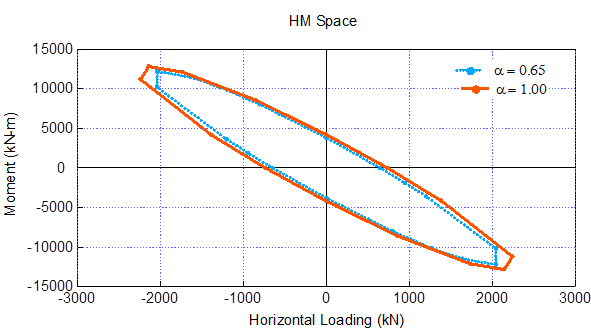
The envelopes of failure in the HM and MV planes were obtained numerically and presented in Figures 12 and 13. The rotated elliptical envelopes in the HM plane are shown in Figure 12 for two different side shear factors. The envelope associated with α = 1 encloses the surface of α = 0.65 and both are symmetrical. The surrounding envelope (for α = 1) varies in lateral capacity from -2239 to 2239 kN and exhibit rotational capacity ranging from 12230 to -12230 kN-m. The discrepancies between the yield surfaces for α = 1 and α = 0.65 ranges from 5% to 15%. It is important to note that the differences observed in the failure mechanisms associated with the direction of the applied driving moment (Figure 11) do not have any impact on the symmetry of the yield surfaces.
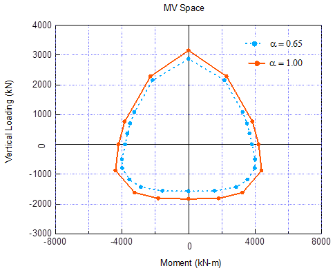
In addition, Figure 13 shows the thong-shape failure envelopes in the MV plane for two different side shear factors. Once again, the yield surface associated with α = 1 surrounds the envelope of α = 0.65. In this case, symmetry appears only with respect to the driving moment axe and vertical capacities are clearly no symmetrical for compressional and extensional loading. The envelope for α = 1 varies in vertical capacity from 3155 to -1828 kN, while rotational capacity exhibits symmetry in the range from 4387 to -4387 kN-m. Differences between the yield surfaces for α = 1 and α = 0.65 ranges from 10% to 16%. Pure compression capacity is 72% higher than pure pull-out capacity.
It is important to point out that the maximum values of vertical capacity in compression and extension correspond to the condition of zero moment applied. In contrast, the maximum positive and negative rotational capacities (4387 and -4387 kN-m) correspond to the extensional vertical capacity of -877 kN.
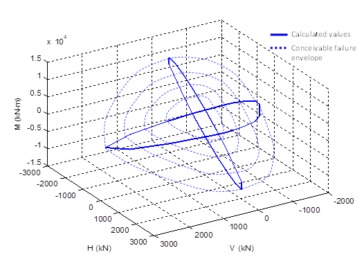
Finally, the complex interaction of the vertical, horizontal and moment loads acting simultaneously on the suction caisson is presented in Figure 14. It can be seen the three-dimensional view of the coupled HM and MV failure envelopes for α = 1.
Conclusions
Application of suction caissons is widely used to anchor floating and submarine systems to exploit hydrocarbons at deep water sites. Suction caissons used for fixing subsea systems to the sea floor are subjected to combinations of lateral and vertical loading (H and V, respectively) and moments (M).
The combined capacity of the caisson was evaluated using numerical modeling to obtain the coupled failure envelope for VHM loading. Finite element models of suction caissons with 5 m of diameter and aspect ratios of 1.5 and 3 were developed using the program ANSYS® 14.5.
Capacity of the caisson was evaluated by means of the load-displacement curves and the failure criterion for lateral and axial loading was defined when displacements reach 10% of the diameter size. In the case of rotational capacity, the moment of failure was identified as the curve exhibits asymptotical behavior (beyond about 1° of rotation angle). The HM capacity results of model with aspect ratio 1.5 met successfully with similar results reported by Palix et al. (2010).
The mechanisms of failure of the suction caissons loaded at the head depend on the aspect ratio and loading orientation. Caissons subjected to horizontal and moment loads in positive convention might exhibit external-scoop mechanisms, while caisson under positive lateral loading and negative moments might exhibit translational or rotational failure modes.
Failure envelopes in HM space have elliptical rotated shapes and envelopes corresponding to adherence factor α = 1 were always the biggest; discrepancies between the yield surfaces for α = 1 and α = 0.65 ranges from 10% to 16%. Otherwise, yield surfaces of MV plane exhibit thong-shape failure and are clearly non-symmetrical, being the compression capacity 72% higher than the extension capacity.

