


 text new page (beta)
 English (pdf)
 Article in xml format
 Article references
 Send this article by e-mail
 Cited by SciELO
  Similars in
SciELO
Similars in
SciELO 
 Permalink
Introduction
The car following situations had been studied over the years because of its importance in understanding and predicting human behavior to accelerate and brake (Carrillo et al., 2015). Brakes are one of the most important safety systems in a motor vehicle. The main functions are to decelerate, to maintain the speed during downhill operation, and finally to park the vehicle stationary either a flat or sloped road condition. The first two functions are related to the service brakes, while the last function is referred to the secondary or parking brakes (Limpert, 1999). The basic principle of the brake system is to provide the clamping force between the disc/pad and drum/lining. Insufficient clamping force may cause the vehicle to fail to decelerate or stop as intended. This may cause danger to the vehicle, driver, passengers, pedestrians and other road users. In ground vehicles, mechanical parking brake is a mechanism to hold the vehicle stationary either a flat or sloped road. It consists of a cable that is directly connected to the brake unit on one end and to an actuating lever on the other end. Several mechanical configurations have been tested via computer simulation (Bortoni et al., 2013). This actuating mechanism is often a hand-operated lever or a pull handle, or a foot-operated pedal (Limpert, 1999). The European Economic Community (EEC) regulation (U.N. Inland Transport Division, 2008) specified that the handbrake system of a laden vehicle in class M1 (passenger cars comprising no more than eight seats in addition to the driver’s seat) must be able to hold the vehicle in 20% gradient. Thiessen (1987) suggested that the parking brake is designed to hold a vehicle stationary over any desired time period. In addition, the parking brake should be able to hold a vehicle stationary for 30% gradient with a maximum applied force on the parking brake pedal of 445 N for a vehicle with the hand-operated parking brake lever. Federal Motor Vehicle Safety Standard (FMVSS) 135 (U.S. National Highway, 2005) specified that, for standard passenger vehicles with weight of 3500 kg and below, the vehicle should be able to stay stationary on 20% grade road for 5 minutes in both forward and reverse directions, with 400 N or less force applied at the hand control of the parking brake mechanism. To date, a lot of literatures have discussed the braking performance of the service brakes (Limpert, 1999, Xiaoyan et al., 2012; Tirovic et al., 2011; Hwang et al., 2009; Koylu and Cinar, 2012; Zhang et al., 2012; Belhocine and Bouchetara, 2012; Tao and Chang, 2003; Aleksendric and Barton, 2009; Bao et al., 2012; Mutlu et al., 2005), but only a handful have been done on the parking brakes. For instance (McKinlay et al., 2003; McKinlay et al., 2006); investigated conventional parking brake performance in term of vehicle roll away for the disc brakes through laboratory tests and theoretical approaches. In the theoretical approach, one-dimensional (1-D) lumped parameter model of disc-type parking brake system using simple linear spring element had been proposed to predict the clamping force. A laboratory parking brake test rig was then developed to measure the clamping force of the parking brake system, which is used to validate the results from the 1-D model. In their study, they had been considered the thermal effects on the braking torque and vehicle roll away. Recently, Rozaini et al. (2013) investigated fully mechanical parking brake system in terms of torque performance using combined analytical-experimental approach without considering thermal effects. They developed one dimensional rigid parking brake model and validated the model by comparing brake torque versus hand-brake lever force over measured data. To the authors’ knowledge, there is no information available in the public domain to investigate the torque performance of a drum-type parking brake system with thermal effect. Thus, the current work attempts to establish a theoretical model of the drum parking brake and validate the results against test results measured from the parking brake test bench.
Parking brake tests
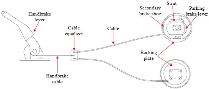
In this work parking brake test bench (Rozaini et al., 2013) for a typical full mechanical hand lever operated, drum-type parking brake system as shown in Figure 1 was used. The test bench consists of a set of parking brake mechanism connected to a pair of rear-drum brake unit, two hydraulic pumps, an actuator, a flywheel, a 5.5 kW DC motor with speed controller, and one load cell. One of the hydraulic pumps is used to supply brake pressure to the drum brake to simulate the brake in normal operations, which heat up the brake unit, whilst the other one is connected to the actuator, which is used to pull a cable that connects to the flywheel and the load cell. This will measure brake torque produced by the drum brake unit when the hand lever is being pulled (McKinlay et al., 2004). To engage the parking brake, force on the hand lever is applied using deadweight that is connected to the hand lever using cable and pulley. The DC motor rotates the drum brake and as the drum rotates, the friction force will create heat and will increase it over a time period.

After the test bench is being developed, verification and calibration process is carried out by comparing the force of the load cell with the applied force to lift the hand lever of an actual car. Having been satisfied with the calibration process, the test bench was ready to be used. In this work, the test was conducted by heating up the drum brake for different hand-brake applied forces until it reached the maximum temperature of 2500C. Standard initial temperature to test the effect vehicle roll away phenomenon stated by McKinlay et al. (2004) is 300°C. However, using the available motor, that temperature level is difficult to be achieved. This is because, during the dragging process, drum and lining temperature will increase drastically so as the coefficient of friction at lining’s/drum’s interface. When the friction coefficient is too high, the torque produced by the drum brake is much higher than the torque of the DC motor. This causes the DC motor to stop. Due to this problem, dragging process can only be executed until the drum surface temperature achieves around 250°C. After the dragging process, delay time is allocated to set up the cable actuator to drive wheel so that external torque could be applied to drive shaft after the rear drum unit heated. The delay time causes the drum temperature drops. Therefore, this test is run with the initial temperature at 200°C. The temperature of the outer surface of the drum is measured using a non-contact temperature sensor (Brand: Cole-Parmer N-08406-00). Since the outer surface of the drum is exposed to the ambient air, it is expected that the drum will be cooled down much faster than the shoes and hence, the drum will be shrinking early than the shoes. Then, the parking brake torque was measured five minute intervals (Day et al., 1984) up to one hour.
Cooling model
Temperature change ΔT is the increment of drum temperature Tt at the specific time t in relation to its initial temperature, too, which is the temperature when the hand-brake lever was initially applied. Thus, the temperature change will be
With the assumption of convection is dominant in the cooling process (Wolff, 2010), the temperature at certain times Tt is
Analysis of brake torque
In the parking brake analysis, two models are used, i.e. parking brake model and on-slope vehicle model. The first model is employed to calculate brake torque produced by the parking brake system whilst the vehicle model is used to determine torque that needs to hold the vehicle stationary. The vehicle is said to be rolled away if the torque from the vehicle model exceeds the torque from the parking brake model.
Parking brake model
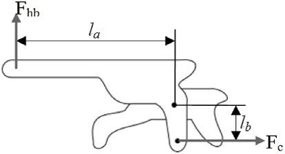
Figure 2 shows the arrangement of a parking brake system used in this work. This arrangement is schematically represented as one dimensional model using linear spring as shown in Figure 3. The model is based on McKinlay model (McKinlay et al. 2004) and it has been modified to suit this study. The derivation of the parking brake torque starts from hand-brake lever and it is transmitted through the brake cable. Engagement of the hand-brake lever cause tension Fc in the cable (Figure 4), which always depend on the force applied Fhb to the lever and the hand lever arm length, la. This is reacted by the force in the cable and the cable lever arm length, lb. Figure 4 illustrates the forces on the hand-brake lever, the length of hand lever arms, la and the length of the cable lever arm, lb.

Then from Figure 5, ratio of reaction forces at the brake shoe is
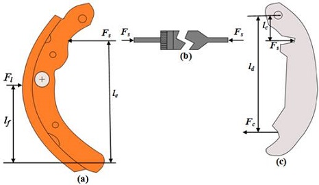
When the brake shoe pushes the drum brake, the deformation of the lining (u6) and the drum (u7) will be occurred. This deformation can be used to find the relationship between the force and the deformation of the lining and the drum. The force of deformable component is generally given by
where
Fc (N) |
= cable load |
Ac (m2) |
= cross sectional area |
Ec (Nm-2) |
= modulus of elasticity |
δc (m) |
= linear deformation and |
lc (m) |
= is the initial thickness of the component |
When the reaction force between the brake lining and drum brake interface is equal and the deformation of both parts formed due to force reaction and thermal effect, the force between the interfaces will be derived as
where
When the radial load
By substituting F from Eq. (4) into Eq. (6), the equation will expand to
where
δl,d and δT,d |
= drum displacement due to radial load and thermal reactions respectively |
δl,l and δT,l |
= displacements of lining due to radial and thermal loads, respectively |
As illustrated in Figure 3, the radial deformation against the lining is u6 and the radial deformation at the drum/lining interface is u7. Assuming that the drum and lining are homogeneous, the deformations of both components in relation to the thermal change δT is proportional to both the temperature change and the thickness of the component. Hence
where
Temperature change ΔT is the increment of drum temperature Tt at the specific time t in relation to its initial temperature, too, which is the temperature when the hand-brake lever was initially applied. Thus, the temperature change will be
With the assumption of convection is dominant in the cooling process (Wolff, 2010), the temperature at certain times Tt is
where
Tamb |
= ambient temperature |
h |
= heat transfer coefficient |
A |
= surface area where heat being transferred |
ρ |
= density of the drum |
cp |
= drum specific heat capacity per unit mass |
V |
= volume of the drum |
After all the deformations in Eq. (7) are substituted, the equation becomes
To cancel out the denominators in Eq. (11), lol lod is multiplied to the equation. A new force equation is formed as follows
By rearranging Eq. (12) to solve for u7 which is the displacement between brake shoe/drum brake interfaces, can be represented by
With equation of deformation, the radial force at the frictional interface is represented by
By replacing the thermal deformation and force deformation into the equation, the force at the interface becomes
Cancelling out the original drum thickness in the equation, the normal force without installation gap will be given as
If the installation gap
In order to calculate the torque generated at drum brake, Tqgen the radial force at the interface, Ff is multiplied by the radius of the drum brake, rd.
Due to design configurations of the drum brake, the applied force at the handbrake lever is different when the vehicle is parked facing uphill or downhill. This can be seen from the forces acting on the brake shoe as depicted in Figures 6a and 6b.

From the Figures 6a and 6b, it can be formulated that the total moment at point 0 is
By substituting Eqs. (1), (2) and (3) into Eqs. (18) and (19), The hand-brake applied force Fhb can be given as
Vehicle model on a slope
Figure 7 shows a vehicle of certain mass m is parked on gradient θ. The weight (mg) of the vehicle is located at the centroid of the vehicle. The weight (mg) of the vehicle acts through its center of gravity (CG). Depending on the incline angle, the weight pulls the vehicle to the ground and pulls it either backward or forward. The weight and the reaction forces are resolved along the road, x´ direction and perpendicular to the road, y´ direction. Normal force, N, at each tyre is perpendicular to the road. The frictional force is assumed only at the rear tyre because the parking brake system is attached at the rear wheels. Thus, the force equation in x´ direction is

As the braking torque of the tyre is equal to the multiplication of frictional force at the tyre and the radius of the wheel, the torque required at the center of the rear wheel to hold the vehicle stationary is
Results and discussion
In this section, the results are discussed; starting with the verification of the test bench, followed by the prediction of temperature and torque generated by the drum brake. Finally, the parametric study is carried out.
Verification of the test bench
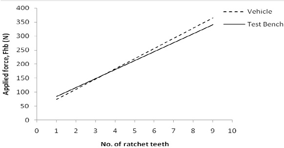
Prior to carrying out the experiment on the test bench, the test bench must closely behave as the actual parking brake performance. This is done by comparing the applied force on the actual hand lever in the vehicle with the dead weight applied on the test bench. The applied forces on both hand-brake levers were based on the number of ratchet teeth the arm went through. The in-vehicle hand-brake force is measured using a spring scale, which is hooked to the handle of the hand-brake and the scale is positioned perpendicular to the lever. The reading was taken once the ratchet pawl slips. In the test bench, deadweight is used to pull the hand-brake lever up to 340N. Figure 8 shows result of the two tests and the results show there is a close correlation between them. This indicates that the test bench can be used in replacing the vehicle test.
Prediction of temperature and parking brake torque
Predictions of temperature and parking brake torque are made based on Eq. (10) and Eq. (17), respectively. All the parameters and their values used to predict the temperature and torque are given in Table 1. Most of the parameters are measured values of the brake components and some of them are taken from other resources as stated in Table 1.
Table 1 Parameters and values used in the parking brake model
| Parameters | Value | Unit | Parameters | Value | Unit |
|---|---|---|---|---|---|
| Ambient Temperature, Tamb | 27 | °C | Modulus Young of lining, El | 2.1 x 10⁸ (Wolff et al. 2010) | Nm-2 |
| Mass of vehicle, m | 1250 | kg | Surface area of drum, Ad | 2.2×10⁻³ | m2 |
| Mass of driver, md | 70 | kg | Surface area of lining, Al | 4.8×10⁻³ | m2 |
| Volume of drum, V | 7.7 x 10⁻⁴ | m3 | Thermal expansion coefficient of drum, αd | 1.1 × 10⁻⁵ (Limpert,1999) | °C-1 |
| Radius of drum, rd | 0.09 | m | Thermal expansion coefficient of lining, αl | 1.2 × 10⁻⁵ ( see.ref,1998) | °C-1 |
| Specific heat capacity of drum, cp | 586 ( see.ref,1998) | J kg-1 °C-1 | Drum thickness, lod | 0.008 | m |
| Density of drum, ρ | 7100 (Day et al.,1984) | kg m-3 | Lining thickness, lol | 0.004 | m |
| Radius of wheel, Rwheel | 0.3 | m | Friction coefficient (shoes/drum) | 0.3~0.6 | |
| Modulus Young of drum, Ed | 1.1 × 10¹¹ (Wolff et al., 2010) | Nm-2 | Initial gap between lining and drum | 1 | mm |
Figure 9a shows that the temperature varies with cooling time after the wheel was run with the brake applied until a temperature of 200oC was reached. It is seen that a quick temperature drop occurs at the start of cooling time before 500s and then, the temperature drop is more gradual. It is also observed that there is no significant difference in the cooling temperature curve for all cases of hand-brake applied forces. In addition, similar temperature curves are also predicted for the downhill and uphill direction. These prediction results are almost identical to the results obtained in the experiment as shown in Figure 9b. From the cooling temperature curve, the normal force in Eq. (16) can be calculated and later, the parking brake torque can also be predicted. From the experiment, it is found that u6 in Eq. (16b) can be represented by

Having known the relationship of temperature change and cooling time, the torque generated by the parking brake can be obtained for various hand-brake applied forces. Figure 10 depicts parking brake torque curves calculated from Eq. (17) in the downhill direction and it can be seen that a good correlation is achieved against measured data. From this correlation, parking brake torque for FhbC = 400N can be predicted using the same equation. A good correlation is also achieved for the uphill direction as plotted in Figure 11. From these two plots, it shows that the parking brake torque generated is much higher in the downhill direction than the uphill direction with the same applied force of Fhb = 400N. This is due to the design of the drum brake leading-trailing shoe mechanism (Limpert, 1999) and is also supported by Eqs. (20) and (21). The significant observation in the results as shown in Figure 10 and Figure 11 is that the drum brake torque is not very much affected by temperature variations of the brake. This is differed with the finding of McKinlay et al. (2004) for the disc brake. The reason can be due to the curved shape of the brake shoes and drum compared to the flat shape of the brake pads and disc. The brake pad can easily be detached from the disc surface during the cooling process. Another possible reason is that the normal brake pad movement is much smaller compared to the brake shoes, thus would have a larger ratio of disengagement when the disc cools off. For these two reasons, the clamping force and brake torque will be reduced significantly.


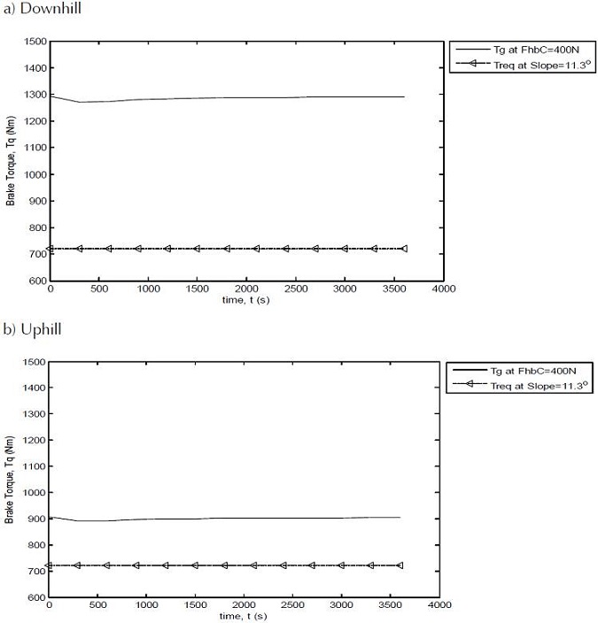
According to FMVSS 135 (U.S. National Highway, 2005), a vehicle weighing 3500 kg and below should be able to remain stationary on 20% or 11.3o grade roads for 5 minutes in both forward and reverse direction when 400N or less force is applied at the hand control mechanism. From Figure 12, the torque generated by the parking brake in the downhill and uphill direction at Fhb = 400N is much higher than the torque required for a slope of 11.3o. This indicates that the current parking brake design that is used in this work complies with FMVSS 135 regulation.
Parametric studies
After the parking brake model is validated, the model can be used to predict brake torque performance due to changes in some of the parameters of the brake components and the vehicle. They are the drum/lining coefficient of friction and the vehicle weight. The effect of the installation gap between the shoes and the drum is not considered because the motivation of this work is to investigate thermal effect which is required the shoes always in contact with the drum. To ensure a vehicle in a stationary state, the torque generated by the parking brake must always be higher than the torque required for certain road slope (Tgen > Treq). This is shown in Figure 13 that the vehicle is in a stationary condition on the slanting road when the friction coefficient between drum and lining is above 0.2.
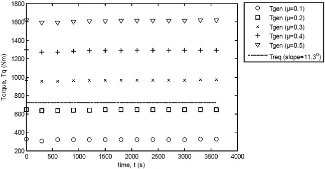
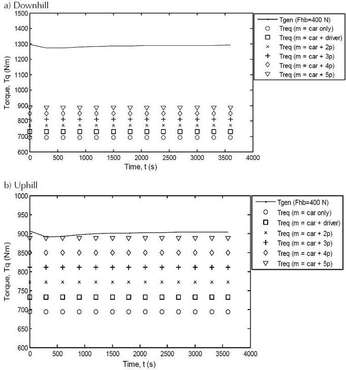
Figure 14a and Figure 14b show the brake torque performance with various vehicle weights in the downhill and uphill direction, respectively. As stated in Table 1, the weight of the vehicle is 1250 kg and the passenger weight is assumed to be 70 kg per person. It shows that the vehicle will not roll away in the uphill and downhill direction, even though there are five passengers inside the vehicle. This is because the torque generated by the parking brake is much higher than the torque required with five passengers.
Conclusion
This paper attempts to find the validated parking brake model in order to predict its torque performance with the aim to avoid vehicle roll away phenomena from the parked condition. In doing so, parking brake test bench was firstly developed with the intention to validate the parking brake model. To ensure the validity of the bench, a comparison was made against vehicle test data and a better agreement was demonstrated between them. Then, one dimensional parking brake model with consideration of the temperature effect is proposed. A good correlation of temperature change and parking brake torque between the model and the test bench was also demonstrated. In addition, the parking brake unit used in this work was identified as comply with the FMVSS 135 regulation. The result also shows that the torque generated by the parking brake in the downhill direction is much higher than in the uphill direction. This is due to the leading-trailing shoe type used in the drum brake mechanism. It is observed that the drum brake torque is not very much affected by temperature reduction. Thus, temperature effect on the drum parking brake is not an issue for vehicle roll away. From the parametric studies, it is seen that the vehicle will not roll away when the friction coefficient of the brake lining is above 0.2 and that the parking brake can hold the vehicle stationary with five occupants inside it.

