


 nueva página del texto (beta)
 Inglés (pdf)
 Artículo en XML
 Referencias del artículo
 Enviar artículo por email
 Citado por SciELO
  Similares en
SciELO
Similares en
SciELO 
 Permalink
Introduction
In the soft soils of Mexico City, friction piles have been used to reduce settlements (the design is in terms of deformation), most commonly as part of a box-type foundation. Less frequently, they have been used to support the total load of the structure and ensure the stability of the foundation (the design is in terms of bearing capacity). In all cases, a complex interaction develops between the subsoil, the piles and the structure. The subsoil is subjected to a double consolidation process: one of them is induced by the weight of the structure and the other is due to the decrease of pore water pressures caused by the intense pumping of the groundwater of the city that induces regional subsidence. The analysis and the design of foundations with friction piles in these difficult conditions is further complicated when the effect of transient loads such as seismic or wind loads is considered.
Worldwide, a substantial number of field studies related to the development of negative skin friction in individual piles have been performed (Plomp and Mierlo, 1948; Bjerrum et al., 1969; Endo et al., 1969; Walker and Darvall, 1973; Auvinet and Hanel, 1981; Bozuzuk, 1981; Clemente, 1981; Fellenius, 1998), while only one publication with respect to laboratory studies of individual piles (Leung et al., 2004) has been found in the literature.
Zeevaert (1957; 1963), Reséndiz and Auvinet (1973), Auvinet and Díaz-Mora (1981), Alberro and Hernández (2000) and Rodríguez (2011) have proposed analytical models for the analysis and design of friction piles foundations interacting with regional subsidence. Nowadays, numerical models such as the Finite Element Method (FEM) offer new possibilities for the analysis of foundations subjected to negative skin friction (Jeong et al., 1997; (2004; (Auvinet and Rodríguez, 2001; 2002; Lee and Charles, 2004; Comodromos and Bareka, 2005; Rodríguez 2011; Rodriguez et al., 2015). These models allow a detailed evaluation of the magnitude of the developed stresses at the piles tips and shafts, as well as the consequent deformations.
In this paper, the results of numerical analyses developed by the authors, based on two dimensional (2D FEM, axisymmetric) and three dimensional (3D FEM) finite element method, of friction piles in typical Mexico City soil and piezometric conditions, are presented. From these results some criteria for the design of this type of foundation have been developed and proposed to be included in the new Mexico City building code.
In the first part of this work, the analysis of the behavior of an individual friction pile subjected to negative skin friction and transient loads (seism or wind) using 2D FEM, is presented. This analysis reproduces field and laboratory research on individual point bearing piles developed by Fellenius (1998), Bozuzuk (1981) and Leung et al. (2004). In the second part, the study of an internal pile within a pile group subjected to the weight of the structure and to negative skin friction using also 2D FEM, is shown. Finally, for the same conditions, some 3D FEM analyses are presented in order to describe the behavior of border and corner piles. Some design criteria are presented regarding design loads and negative skin friction for internal, border and corner piles.
Negative skin friction
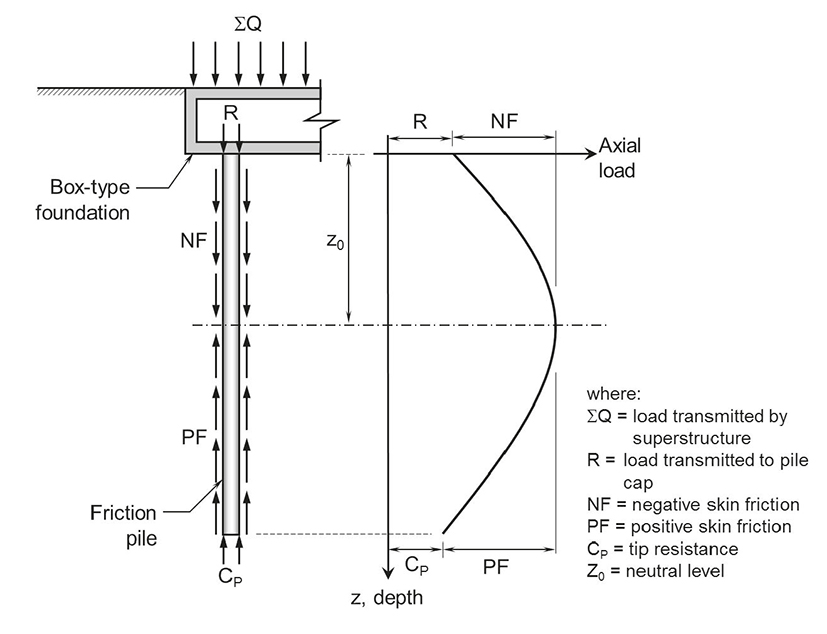
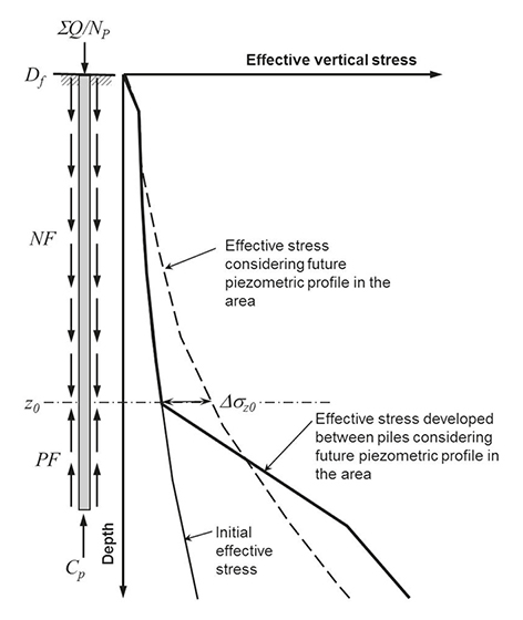
Negative skin friction (NF) can be defined as the downward traction that develops along the piles shaft when the surrounding soil consolidates due to piezometric drawdown or to surface loading. The forces that resist the penetration of piles are the positive skin friction (PF) and the tip resistance (CP), Figure 1. The depth where the relative displacements between pile and soil are nil and where skin friction changes from negative to positive is called neutral level (z0).
Single friction pile subjected to NF and transient loads
Field tests results
Fellenius (1998) presents the results of more than seven years of measured NF developed in two 30cm diameter driven concrete piles (Figure 2a). These piles were driven through a 40m thick compressible layer formed by clays and silts. Their tips are located at a depth of 52m in compact silty sand. The developed NF was due both to a slight regional subsidence and to an external load placed around the piles caps.
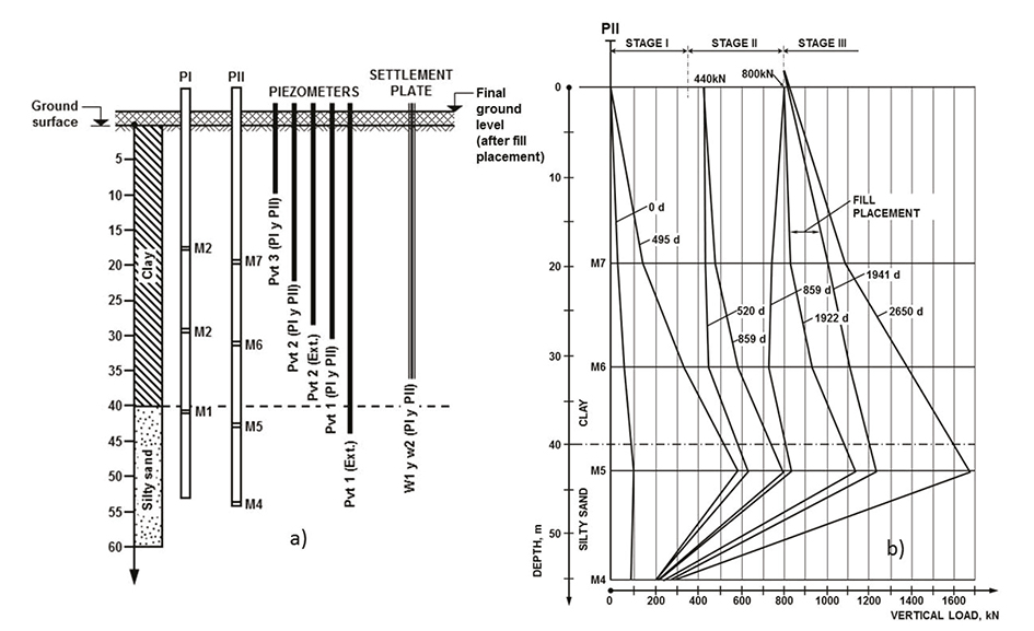
Figure 2 a) Soil conditions and pile and site instrumentation, and b) vertical distribution of load in Pile II (obtained and modified from Bjerin, 1977)
In Figure 2b the results of seven years of measurements made on one of the instrumented piles (pile II) for different stages of the tests, are shown. During pile installation (after driving, t=0d) an increase of axial load due to the soil re-consolidation induced by the excess pore pressure dissipation was observed. After 495 days (Stage I, t=495d) NF developed along the pile shaft due to regional subsidence down to gauge M5. At Stage II (t=520d), NF between the surface and gauge M6 practically disappeared when a 440kN load was applied at the pile cap and a negligible increment of the maximum axial load (gauge M5) was observed. After 330 days (t=850d) NF had recovered and a substantial increment of the maximum axial load was measured. At Stage III (t=850d), when a new 360kN load was added on the pile cap, NF disappeared and even became positive from surface through gauge M6 and again no significant increment of the maximum axial load was observed. After 1072 days (t=1922d), for a second time, NF recovered and the maximum axial load substantially increased.
Meanwhile, in 1981, in Canada, Bozuzuk showed the results of a ten years field test developed in a 49m long and 32.4cm diameter steel pile, which was subjected to NF due to consolidation of a 73m thick marine clay, generated by a 10m high sandy embankment (Figure 3a).
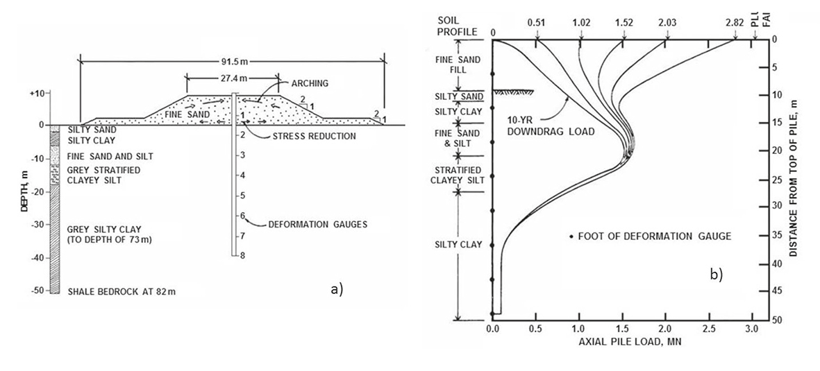
Figure 3 a) Installation of steel-pipe pile through sand embankment and b) load distribution in teste pile (Bozuzuk, 1981)
In Figure 3b the variation with depth of the developed axial load in the pile is presented. It can be seen that, after ten years of pile driving, the maximum developed axial load (Qmax) was about 1.52MN. Then, a two stages bearing capacity test was performed. At the first stage an external load equal to Qmax was applied in three increments, in a total period of 11 days. After this period the load was removed, letting the pile to rest for three days. For the second stage the load was increased to 2Qmax, also in three increments but in a total period of seven days.
It is possible to observe that the obtained results are similar to those reported by Fellenius, since when the incremental external load is applied, NF decreases and even turns to positive and Qmax remains almost the same.
In both field tests it was shown that piles who developed negative skin friction behaved as preloaded elements that are able to carry on external loads (such as transient loads due to seism or wind) with no increase of the developed maximum axial pile load.
Laboratory test results
In 2004, Leung et al. (2004) present the results obtained from a scale centrifuge model developed in order to investigate the NF in piles installed in soft clays which consolidate due to their own weight and the weight of a shallow sand fill. Also, the behavior of the pile under the combined effect of the developed NF and an external load applied on the pile cap was studied.
The study consists in modeling the behavior of an instrumented hollow pile 18.5m long and 1.6m in diameter, placed through a 16m thick soft clay layer and resting on a compacted sand (Figure 4a).
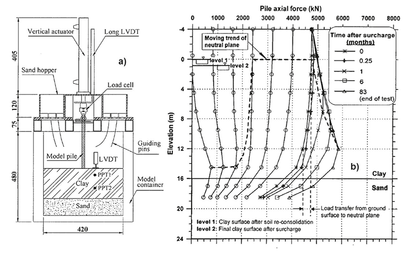
Figure 4 a) Centrifuge model setup (units in mm), b) effect of applied load on the shifting of neutral plane (Test A1) (Leung et al., 2004)
Figure 4b presents part of the published results of the tested model in which the combined effects of NF and external load on the pile cap were evaluated. The first curve from left to right represents the measured axial load along the pile at the end of the consolidation of the clay by own weight. The following six curves show the developed axial load due to an external load of about 4.750kN, equivalent to 50% of the ultimate strength of the pile, applied in six increments. Immediately afterwards, the sand fill was placed and left in the hopper until the end of the consolidation of the clay (83 months).
The results obtained in the field tests were confirmed: the developed NF is gradually replaced by the applied external load and becomes positive. Additionally, it can be observed that the elevation of the neutral level changed when the sand fill was placed, because the initial load conditions were modified.
Numerical modeling
In order to simulate conditions analogous to the field and laboratory studies presented above, a numerical axisymmetric FEM model was developed using PLAXIS 2D finite element code, to analyze the behavior of a single friction pile subjected to NF and transient loads (seism or wind). The study was conducted considering typical stratigraphic and piezometric conditions of Mexico City lacustrine zone.
A 50cm diameter and 25m long friction pile was modeled. The problem was discretized using a finite element mesh (Figure 5) with fifteen-noded triangular elements. The pile-shaft interaction was simulated and discretized using five pair-noded interface elements. The lateral boundary was placed at 10m from pile axis and fixed in the horizontal direction, and the bottom boundary was placed at 31m depth (beneath the hard layer) and fixed in both directions. Sensitivity studies showed that the mesh was dense enough to give accurate results.
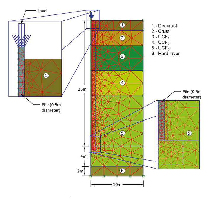
For simulation of the clay behavior (Upper Clay Formation, UFC, Figure 5) the Soft Soil model (a isotropic hardening elasto-plastic model included in PLAXIS code) was used and the crust, dry crust and hard layer were simulated with the Mohr Coulomb model. The stages of the analysis were as follows:
Stage 1: Consolidation due to pile self-weight.
Stage 2: Consolidation due to a typical future pore pressure drawdown (Hypothesis #1, Figure 6).
Stage 3: A total load of 500 kN was placed on the pile cap in undrained conditions (transient load) and in five increments.
Stage 4: Consolidation due to the load of 500 kN.
Stage 5: Consolidation due to a second pore pressure drawdown (extreme but possible condition, Hypothesis #2, Figure 6).

As part of the obtained results, Figure 7 shows the variation with depth of the axial load transmitted by the pile (Q pile) during the different stages of the analysis. From these results, it can be observed that:
For Stage 1, the pile self-weight induces an axial load that increases with depth with a maximum value of 90kN.
In Stage 2, for the different consolidation degrees of the pore pressure drawdown (U = 20 to 100%), the neutral level remains at a depth of about 20m (neutral level #1).
As the transient load is gradually placed (load applied in undrained conditions, Stage 3) the NF is progressively replaced by the applied load, even for values greater than 300 kN, and a second neutral level develops at a depth of 4m (neutral level #2).
As the second pore pressure drawdown develops (Step 5), the positive skin friction generated at the pile top due to the transient load tends to disappear and the neutral level stabilizes at a depth of 16.5m (neutral level #3).
There is a significant shift of neutral level depth from Step 2 (neutral level #1) to Stage 5 (neutral level #3), because the initial loading conditions for both steps are different.

Important similarities are found between the results obtained for friction piles by FEM with those reported by Bjerin, Bozuzuk and Leung for point bearing piles in the field. One of the most important is that a huge part of the developed NF can be replaced by transient loads and NF can even become positive. Therefore, for the design of piles under these conditions, it would be too conservative to add the effects of the NF and transient loads.
The analysis also confirms that (Reséndiz and Auvinet, 1973) the depth of the neutral level tends to stabilize as the consolidation process due to pore pressure drawdown develops; it is also demonstrated that the depth of such level depends significantly on the initial pile load conditions.
Additionally, in Figure 8 the variation of the pile cap displacement with the applied transient load for a pile previously subjected to NF due to pore pressure drawdown and for another pile not subjected to this condition is shown. It can be seen that, in the first case, the pile develops an elastic behavior (linear load-displacement relationship) until the 500 kN, i.e., until the applied force exceeds the maximum NF developed in the pile. This can be compared to the behavior a pre-loaded element (Fellenius, 1998). Accordingly, the displacements obtained are considerably lower than those obtained when pore pressure drawdown is not considered.

Internal pile within a pile group
The numerical modeling of the behavior of an internal pile within an infinite pile group can be carried out considering that approximately axisymmetric conditions prevail around each pile, Figure 9 (Auvinet and Rodriguez, 2001). For finite pile groups, this assumption is not valid for border and corner elements but for large pile groups the boundary condition loses relevance.
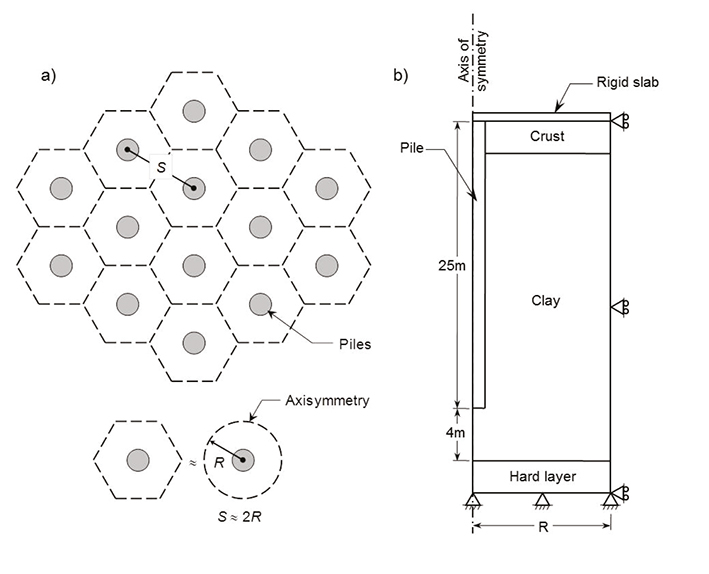
Figure 9 Model of a pile raft, a) infinitely large pile raft supported by friction piles, b) numerical model (not at scale) (modified from Auvinet and Rodriguez, 2001)
The analysis was conducted considering the same stratigraphic and piezometric conditions of the single pile study presented before (Figures 5 and 6 ), but in this case the analysis stages were as follows:
Stage 1: Consolidation due to a 75kPa external load (representing the weight of the structure), applied directly under the foundation slab.
Stage 2: Consolidation due to typical future pore pressure drawdown (Figure 6).
Stage 3: Consolidation due to a second pore pressure drawdown (extreme but possible condition, Figure 6).
Figure 10 presents the increments of the vertical effective stresses developed around the pile, for Stages 2 and 3 and for 1.5 and 4m pile spacing. It can be seen that, in all cases, the higher values of the effective stress increment develop near the pile tip.
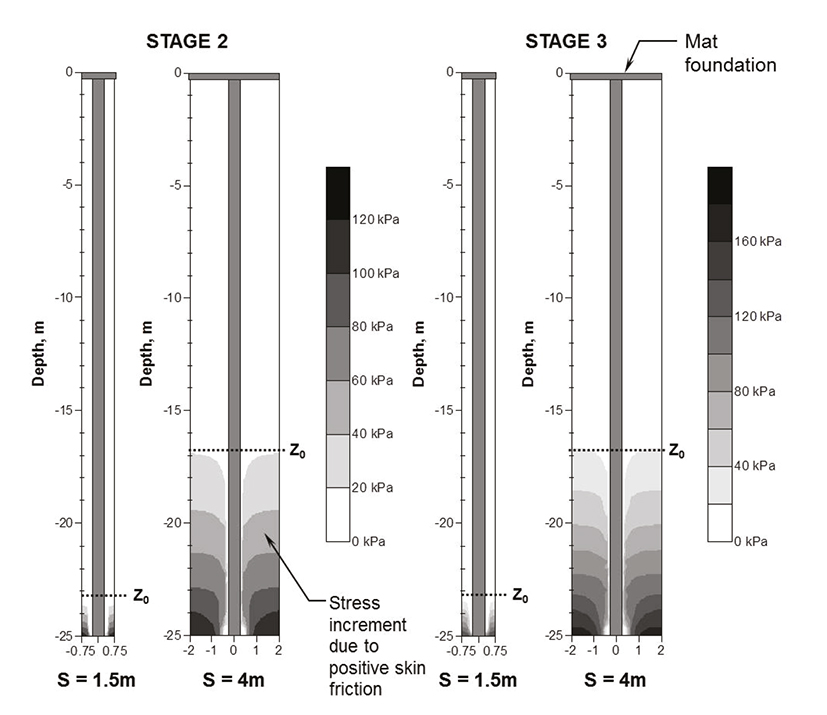
Figure 10 Predicted effective vertical stress increment in soil mass for Stages 2 and 3 and for spacing S = 1.5 and 4.0m
Figure 11a shows the increment of the effective vertical stresses developed in the medium in presence (σ’WP) and absence (σ’WoP) of piles with 1.5m pile spacing and for Stage 3, while Figure 11b shows the increment of effective stress obtained from σ’WP - σ’WoP. The σ’WP - σ’ WoP < 0 condition represents the unloading of the reinforced soil with respect to the surrounding medium. It is possible to see that, above z0 the value of the developed effective stress without piles due to pore pressure drawdown (σ’WoP) decreases almost to zero when the piles are included in the analysis (σ’ WP), i.e. above z0 the soil practically stops consolidating because σ’WP has almost the same value as the initial effective stress (σ’0). This is due to the fact that, the effective stress increment is transmitted almost completely to the pile when the soil hangs from its shaft (σ’WP - σ’ WoP = σ’0 - σ’WoP). Below z0 the soil keeps consolidating due to the σ’WP - σ’0, term in which are included the loads due to the pore pressure drawdown and the weight of the structure.
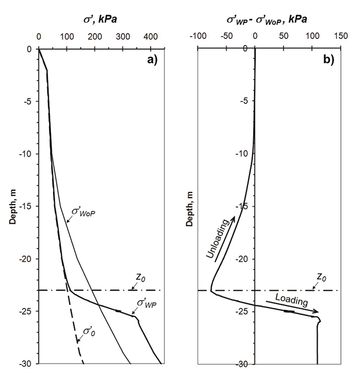
Figure 11 Predicted effective stresses in the soil mass for with and without pile conditions (σ’YWP and σ’ YWoP, respectively), for 1.5m pile spacing and for Stage 3
The pile-soil interaction analysis demonstrates that NF on central piles in consolidating soils cannot be larger than the apparent increase of the submerged weight of the mass of soil surrounding the pile above the neutral level, induced by seepage forces associated to the head gradient caused by pore pressure drawdown.
Border and corner piles
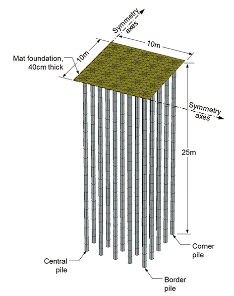
To study the behavior of border and corner piles a three-dimensional model has been developed using PLAXIS 3D finite element code. A square mat foundation of 20m side, representing a typical 5 to 10 stories building surface located in the lacustrine zone of Mexico City, with a total of 100 friction piles uniformly distributed with a 2m spacing, was considered. Due to the symmetry of the problem, it was only necessary to model a quarter of the building surface, so only 25 piles were considered, allowing an adequate mesh refinement, Figure 12. The problem was discretized using a finite element mesh with fifteen-noded wedge elements. The pile-shaft interaction was simulated and discretized using eight pair-noded interface elements. The lateral boundaries were placed at 40m from the symmetric axes and fixed in the horizontal direction, and the bottom boundary was placed at 31m depth (beneath the hard layer) and fixed in both directions. Sensitivity studies showed that the mesh was dense enough to give accurate results. The considered stratigraphy, pore pressure conditions, constitutive soil models and analysis stages were the same as those of the internal pile study presented above.
The variation with depth of the axial load developed in the center, border and corner piles are shown in Figure 13. For Stage 1, the load transmitted by the border piles is larger than for central ones (1.4 times ∑Q), while in the corner values up to 1.74 times ∑Q are attained. Due to the mat stiffness, the transmitted loads tend to concentrate on the borders, and further, at the corners of the mat foundation.
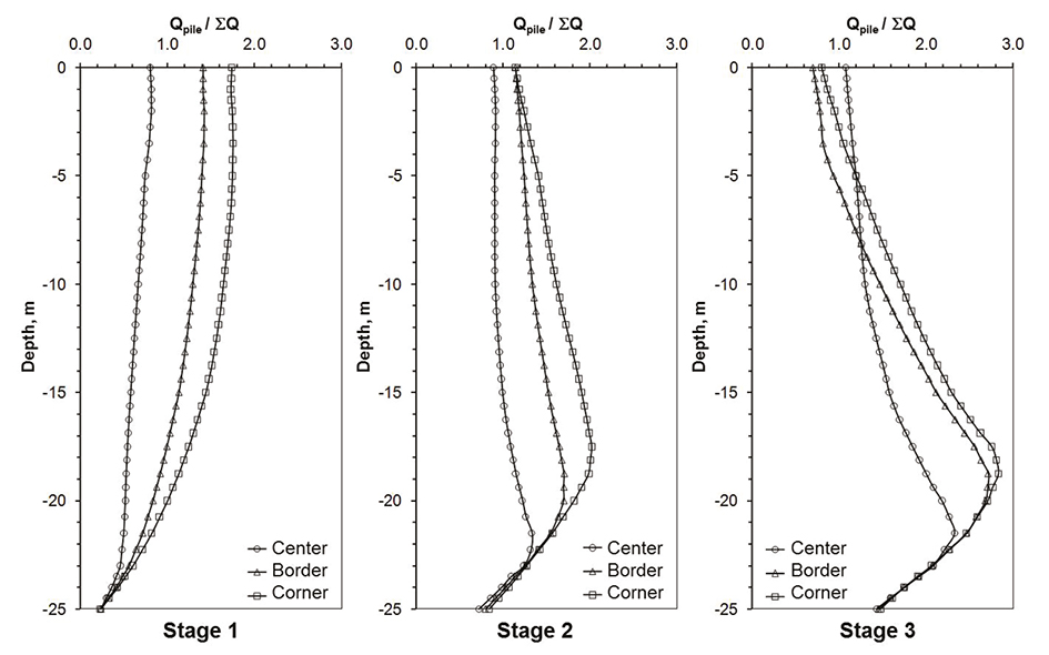
Figure 13 Predicted axial loads in center, border and corner piles, for the three stages of the analysis
For Stages 2 and 3, the settlement developed by pore pressure drawdown has a greater influence on the behavior of the corner piles than on the border and center ones. This can be attributed to the fact that the area of influence of the corner piles is considerably larger than for the others leading to higher NF values.
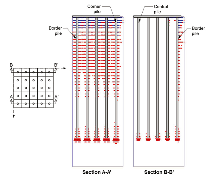
For Stage 3 (Figure 13), small differences in the developed axial loads can be appreciated between border and corner piles, this is due to the fact that, as illustrated in Figure 14, limit shear conditions for NF have been developed for all of the perimeter piles of the group. These limit conditions were not reached for central piles even for stage 3 (extreme pore pressure drawdown).
It is possible to conclude that limit shear conditions for NF can develop for border and corner piles but very unlikely for central ones.
Design criteria for friction piles
Considerations for design loads
This research established that, when pore pressure drawdown occurs, large values of NF can develop. However, under the effect of transient loads (seism or wind) a large part of the developed NF disappears and NF can even become positive. Therefore, for the design of piles under these conditions, it would be too conservative to add the effects of NF and transient loads. Also, for long term conditions, the stiffness of the pile increases because the pile behaves like a preloaded element. Hence, the effect of the NF should be considered only for the structural safety review and for the estimation of the long term displacements (settlements or apparent emersion) of the foundation.
According to the above and adopting the definitions established in the Mexico City standards for foundations (GDF, 2004), for the structural safety review and for the estimation of the long term displacements of friction pile foundations, the loads to be considered should be: permanent loads (AP), live loads with medium intensity (AVmed.) and the effect of the NF developed on piles shafts.
As the NF estimation is a complex problem, it is recommended to have recourse to the explicit numerical modeling of the problem. Conservative assumptions should be adopted regarding the future evolution of the pore pressure drawdown. Alternatively, this estimation can be done as proposed below.
NF for internal piles
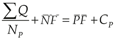
As shown before, for large pile groups, the NF above the neutral level (z0) cannot be greater than the apparent increment of the submerged weight of the soil mass that surrounds the pile. Hence, the magnitude of the NF can be estimated by trial and error, varying the depth of z0, until the following equation is satisfied (Figure 15)
 (1)
(1)
where
∑Q = |
permanent loads plus the live loads with medium intensity |
NP = |
number of piles |
positive skin friction, equal to the lateral bearing capacity developed from z 0 to the depth of the pile tip (Df + LP), considering a unitary strength factor |
|
Cp = |
point bearing capacity, considering a unitary strength factor |
LP = |
pile length |
Df = |
depth of the mat or box-type foundation |
NF = |
negative skin friction |
equal to
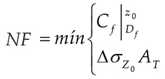 (2)
(2)

Conclusions
The results of numerical analyses developed by the authors, based on two dimensional and three dimensional Finite Element Method (FEM), of friction piles in typically Mexico City soil and piezometric conditions, are presented.
From the analysis of the behavior of an individual friction pile subjected to negative skin friction (NF) and transient loads using 2D FEM, it is concluded that:
There are important similarities between the results obtained for friction piles using FEM with those reported by Bjerin, Bozuzuk and Leung for point bearing piles field. One of the most important results is that a large part of the developed NF can be replaced by transient loads and NF can even become positive. Therefore, for the design of piles under these conditions, it would be too conservative to add the effects of the NF and transient loads.
The depth of the neutral level tends to stabilize as the consolidation process due to pore pressure drawdown develops, also it is demonstrated that the depth of such level depends significantly on the initial pile load conditions.
The behavior of a friction pile, when the pore pressure drawdown is considered, can be compared to a pre-loaded element and therefore, the displacements obtained are considerably lower than those obtained when the pore pressure is not taken into account.
The 2D FEM study of an internal pile within a pile group subjected to the weight of the structure and to negative skin friction shows that NF on central piles in consolidating soils cannot be greater than the apparent increase of the submerged weight of the mass of soil surrounding the pile above the neutral level.
On the other hand, from the 3D FEM analyses it was concluded that limit shear conditions for NF can develop on border and corner piles but are very unlikely to occur for the central ones.
Finally, based on these conclusions, some design criteria were presented in order to be included in the updated (2017) Mexico City building code (complementary standards for foundations):
For the structural safety review and for the estimation of the long term displacements of friction pile foundations, the loads to be considered should be: permanent loads, live loads with medium intensity and the effect of the NF developed on piles shafts.
As the NF estimation is a complex problem, it is recommended to have recourse to the explicit numerical modeling of the problem. Conservative assumptions should be adopted regarding the future evolution of the pore pressure drawdown.
Alternatively to the above, the magnitude of the NF for internal, border or corner piles can be estimated by the equations proposed in this paper.

