


Servicios Personalizados
Revista
Articulo
 Inglés (pdf)
 Artículo en XML
 Referencias del artículo
 Enviar artículo por email
Indicadores
-
 Citado por SciELO
 -
 Accesos
Links relacionados
-
 Similares en
SciELO
Similares en
SciELO
Compartir

 Permalink
Ingeniería, investigación y tecnología
versión On-line ISSN 2594-0732versión impresa ISSN 1405-7743
Ing. invest. y tecnol. vol.12 no.4 Ciudad de México oct./dic. 2011
Clay–Brick Firing in a High–Temperature Solar Furnace
Cocción de tabiques de arcilla en un horno solar de alta temperatura
Villeda–Muñoz G.1, Castañeda–Miranda A.2, Pless R.C.3, Vega–Durán J.T4† and Pineda–Piñón J.5
1 Centro de Investigación en Ciencia Aplicada y Tecnología Avanzada Instituto Politécnico Nacional, Unidad Querétaro. E–mail: gvilledam@ipn.mx
2 Computation & Mechatronic Studies Division Universidad Politécnica de Querétaro. E–mail: acastaneda@upq.edu.mx
3 Centro de Investigación en Ciencia Aplicada y Tecnología Avanzada Instituto Politécnico Nacional, Unidad Querétaro. E–mail: rpless@ipn.mx
4 Centro de Investigación en Ciencia Aplicada y Tecnología Avanzada Instituto Politécnico Nacional, Unidad Querétaro. † Deceased.
5 Centro de Investigación en Ciencia Aplicada y Tecnología Avanzada Instituto Politécnico Nacional, Unidad Querétaro. E–mail: jpinedap@ipn.mx
Article information: received: june 2009.
Reevaluated: march and may 2010.
Accepted: december 2010.
Abstract
The firing process for clay–brick production in traditional kilns generates atmospheric pollution when industrial and domestic scrap is used as fuel. An alternative is presented here, using the solar energy for clay–brick firing. We are developing a system for clay–brick firing to reach temperatures between 900°C and 1050°C; these temperatures are sufficiently high to fire bricks or similar ceramic products. The present paper describes the design and characterization of the components of a solar furnace for clay–brick firing with inner chamber dimensions of 0.48 × 0.61 × 0.64 m. To convey the sunlight to the firing chamber, a heliostat with nine 1 × 1 m mirrors is used to send the rays of the sun to an off–axis parabolic concentrator that focuses the light on the entrance of the firing chamber. The heliostat has a solar–tracking system which makes primary and secondary adjustments to assure that the reflected solar radiation always arrives at the concentrator. The firing chamber contains a prismatic cavity that absorbs the solar radiation to generate the heat which is needed for baking the bricks inside the firing chamber.
Keywords: atmospheric pollution, clay–brick firing, fossil fuels, heliostat, high–temperature solar furnace, solar energy.
Resumen
El proceso de cocción para la producción de tabiques de arcilla en hornos tradicionales genera contaminación atmosférica cuando los desechos industriales y domésticos se usan como combustibles. Aquí se presenta una alternativa, utilizando la energía solar para la cocción de tabiques de arcilla. Estamos desarrollando un sistema para la cocción de tabiques de arcilla para alcanzar temperaturas entre 900°C y 1050°C; estas temperaturas son suficientemente altas para cocer tabiques o productos cerámicos similares. El presente artículo describe el diseño y caracterización de los componentes de un horno solar para la cocción de tabiques de arcilla con una cámara con dimensiones internas de 0.48 × 0.61 × 0.64 m. Para dirigir los rayos solares a la cámara de cocción, un helióstato con nueve espejos de 1 × 1 m se usa para enviar los rayos del Sol a un concentrador parabólico fuera de eje que concentra la luz en la entrada la cámara de cocción. El helióstato tiene un sistema de seguimiento solar que realiza los ajustes para asegurar que la radiación solar siempre llegue al concentrador. La cámara de cocción tiene una cavidad prismática que absorbe la radiación solar para generar el calor, el cual es necesario en la cocción de los tabiques dentro de la cámara de cocción.
Descriptores: contaminación atmosférica, cocción de tabique de arcilla, combustibles fósiles, helióstato, horno solar de alta temperatura, energía solar.
Introduction
Production of clay bricks is a cottage industry on which many third–world families depend. In Mexico there are around 8000 traditional kilns for clay–brick firing. The manual process involves the preparation of a clayey mixture, which is then molded, dried, and finally fired. The firing process generates atmospheric pollution, as tires, firewood, wood residues, diesel oil, and fuel oil are used as the fuel. The use of solar energy would help alleviate environmental pollution; the present paper describes the design and partial testing of a solar system for clay–brick firing.
The combination of a stationary parabolic–dish concentrator and a heliostat has come to be known as solar furnace (Ries et al., 1990). Worldwide there are several solar furnaces, for example the heliostats in Albuquerque, New Mexico, USA (Alpert et al., 1991), the High– Flux solar furnace in Golden, Colorado, USA (Lewandowski et al., 1991), the solar furnace of 1000 kW thermal power in Uzbekistan (Riskiev et al., 1991), the solar furnace in Odeillo, France (Hernandez et al., 2006), the solar furnace in Almería, Spain (Fernández–Reche et al. , 2006), and the non–imaging focusing heliostat with rotation–elevation tracking system in Malaysia (Chen et al., 2001; Chen et al., 2002). The present paper describes the design for a solar furnace, with a rectangular–prism cavity which is heated to 1000°C by the introduction of the reflected solar radiation.
A heliostat with nine mirrors, each with dimensions of 1 x 1 m, is used to reflect sunlight to an off–axis, parabolic out–of–focus concentrator. This concentrator focuses the light into a firing chamber. The off–axis geometry is employed to avoid the firing chamber shadowing the concentrator. All reflecting surfaces are made of anodized aluminum.
Inside the firing chamber is the cavity of rectangular prismatic shape that absorbs the solar radiation and emits the generated heat to bricks placed around the cavity. In order to reduce heat losses, the firing chamber has a composite wall, consisting of an innermost layer of solid refractory ceramic material, followed by an insulating blanket of ceramic fibers, and outermost a carbon–steel sheet cover. The solar furnace was designed to fire 'green' (unfired) bricks obtained from towns like La Solana, Amazcala, and others, all in the state of Querétaro.
The clay–brick firing process
Brick manufacturing uses similar processes in different areas, although the raw material and fuel used may vary by region. The ingredients included in the clayey mixture may differ from area to area, as also the drying time employed, to compensate for varying ambient temperatures. Also, different regions use different arrangements of bricks within the kiln. The brick manufacture process used in the town of La Solana in Querétaro State starts by extracting dry clay from the soil; this is then crushed and coarsely sieved to obtain particles smaller than approximately 0.01 m. The clayey mixture is prepared with the following proportions: 0.2 m3 of clay, 0.1 m3 of sawdust or straw, 0.1 m3 of cow dung, 0.05 m3 of water. These materials are mixed with a shovel until an easy–to–mold material is obtained. The clayey mixture is poured into wooden molds containing six cavities (each with the dimensions of the brick to be formed), previously rinsed with water to eliminate any clay remainders and prevent the later adherence of the bricks. Next, a moistened metal rule is slid across the top face of the bricks to remove any excess material and to obtain a smooth, level surface. The mud–filled forms are then inverted on a clean, moist floor covered with clay dust, to later on facilitate the detachment of the bricks.
During the next two days, the bricks are dried in the sunlight. For this purpose, they are placed on end, in loose lines (with about 0.02 m separation between bricks). Once dry, the bricks are stacked in the traditional kiln, which has one or two shallow ditches, to hold the burning fuel.
The kiln is fired for 12 hours (from the morning to afternoon), with continuous feeding of fuel; it requires 0.8 m3 of burnt oil to fire 10000 bricks. Once the heat has reached the top of the kiln, the latter is covered with a layer of dung, trash, or sawdust. Three days after the beginning of the firing process, the kiln is emptied.
The production of traditional kilns is from 9000 to 13000 bricks per run, with usually only one run per month. The use of fuels such as burnt oil, domestic or industrial scrap, trash, tires, or diesel oil results in major damage to the environment. Alternatively, kilns use wood, thus contributing to deforestation.
Materials and Methods
This section describes the tests used to determine the clay–brick parameters and the design of the solar clay brick–firing system prototype.
Study of Clay–Brick Firing Parameters
The following parameters of the clay bricks were determined: color, weight, compression strength, water absorption, and plasticity. To examine these properties, dry raw clay bricks made by the traditional method at La Solana in Querétaro State were fired in an electric muffle oven (Barnstead/Thermolyne, Model F48055, 120 V, 15 A, 1800 W, 50/60 Hz, monophasic) at different temperatures (800°C, 850°C, 900°C, 950°C, 1000°C, 1050°C, or 1100°C) for 12 hours, simulating a solar day in Querétaro City.
Color was measured with a spectrocolorimeter (Hunter Lab, MiniScan XE); the instrument has a scale in three axes: the L axis, whose maximum value is 100, which would be the case for a perfect reflecting diffuser and the minimum value is zero, which would be black; the a axis has no specific numerical limits, positive is red and negative is green; the b axis has no specific numerical limits, positive is yellow and negative is blue.
The weight difference of the fired brick relative to the 'green' brick was determined with a triple–beam balance (Ohaus, Series 700/800).
The compression strength was determined according to Mexican Norm NMX–C–036–1983 (Dirección General de Normas, 1983). To this end, fired–brick test samples with parallel surfaces were made (with dimensions of 0.055 × 0.06 × 0.07 m); next, molten sulfur was applied to the surfaces where the plates of the universal test machine (Forney, Model LT–1150 with capacity of 150 tons) make contact; finally, the test samples were put under load, starting from 0 kg and gradually increasing until the sample was broken, and the rupture value was recorded.
The water absorption test was performed according to Mexican Norm NMX–C–037–1986 (Dirección General de Normas, 1986). First, test samples of dry fired brick (Ms) were weighed, then they were kept under water for 24 hours, after which time they were taken out of the water, dried superficially and weighed (Msss), and finally the test samples were weighed when submerged in water (Pa). The water absorption (A) is determined with the following equation:

To evaluate the plasticity of the clay used to make the green bricks, its liquid limit and its plastic limit were determined. The liquid limit was measured by the mechanical method, using the appropriate device. The plastic limit was determined as the moisture content of the oven–dried mass derived from clay which had been reworked between the plastic and semisolid states. With the data thus obtained the plastic index of the clay was calculated, using the formula given by Jiménez de Salas and de Justo Alpañes (1975):

where
IP = plastic index of the clay, %
WL = liquid limit of the clay, %
WP = plastic limit of the clay, %.

Thus, the plastic index of the clay used in this work was 15.7%. This clay is suitable for use in the manufacture of bricks, as it is an inorganic clay of low plasticity (type CL), with a significant sand content, which makes for a low linear contraction, and it is a clay of intermediate resilience.
Design of the prototype
The solar system for clay–brick production has three basic components: the heliostat, the off–axis parabolic concentrator, and the firing chamber. A heliostat with nine mirrors of 1 × 1 m each is used; that means a total area of 9 m2. Tracking mechanisms are required in the heliostat for following the trajectory of the sun in the sky with the necessary accuracy (Kalogirou, 2007). The heliostat has a solar–tracking system where each mirror is rotatable about two axes (rotation–elevation), to assure that the solar radiation always arrives at the off–axis parabolic concentrator, which receives the rays of the sun in a smaller area and in turn sends them on into the firing chamber. Figure 1 shows the scheme of the solar furnace with the three basic components: the heliostat mounted on a sun–tracking system, the parabolic surface, and the firing chamber.
The movement of the heliostat occurs at two levels: primary tracking by the entire heliostat and secondary tracking by the slave mirrors (Chen et al., 2001).
Primary tracking of the heliostat is based on two movements (figure 2c): rotation of the heliostat about the T axis (rotation angle p) and rotation of the heliostat about the U axis (elevation angle θ).
The correction movements of the slave mirrors constitute the secondary tracking in the focusing heliostat, and they serve to minimize the first–order aberration effects (Chen et al., 2006). The slave mirrors are grouped into rows and columns; those belonging to the same row are moved as a group by the same motor for their horizontal rotation, as are the slave mirrors within a given column for their vertical rotation (Chen et al., 2001). Figure 3a shows a heliostat with three rows and three columns; the master mirror is located in row 2 and the slave mirrors in rows 1 and 3. The slave mirrors located in the rows rotate about the pivot point through an angle σ in order to assure that the solar rays arrive at the same site (figure 3b); the slave mirrors placed in the columns rotate through an angle γ (figure 3c).
Optical concentrators for solar energy can be made with flat mirrors, and in any case every type of concentrator can be approximated with flat surfaces of sufficiently small area (Pancotti, 2007). Nonetheless, in the present work we opted for fashioning the paraboloid–type concentrator from unidimensionally curved strips made of anodized aluminum, to obtain a Scheffler–type reflector (Scheffler, 2006). The reflector eventually built is shown in figure 4.
The design of the firing chamber, shown in figure 5, is a box which has in its center a cavity of rectangular prismatic shape, made from Hastelloy X plates of 0.013 m thickness. The solar rays enter the cavity through a circular opening; the energy is absorbed by the Hastelloy X walls (in part after multiple reflections), which then transmit the heat by convection and radiation to the bricks stacked around the prismatic cavity. In order to reduce heat losses, the firing chamber is lined with an innermost layer of ceramic refractory material of 0.05 m thickness, an insulating blanket of ceramic fibers of 0.05 m thickness, and, outermost, a 22–gauge carbon–steel sheet cover.

Figure 6 shows the assembled firing chamber before the installation of the insulating blanket and the outermost steel sheet.

The high–temperature solar furnace is designed to fire 10 clay bricks with dimensions of 0.07 × 0.14 × 0.28 m to temperatures between 950°C and 1050°C. For the design of the prototype we considered the following parameters:
– Material for the reflecting surface,
– Energy required to fire one brick,
– Solar radiation throughout a day in Querétaro City,
– Heliostat dimensions,
– Internal temperature for the firing chamber,
– Off–axis parabolic concentrator dimensions.
Material for the reflecting surface
For the reflecting surface four materials were considered:
– Anodized aluminum (Ultrabrite 0.020"), from Aluminum Coil Anodizing Corporation,
– Reflecting film (Decora 23002), from Betterware,
– Reflecting film (P–18ARL), from 3M,
– Back–silvered glass mirror (with a glass thickness of 0.006 m).
The specular reflectance was determined with a spectrophotometer (Varian, Model Cary 5E) from the ultraviolet to the infrared, as shown in figure 7, because, as a result of almost total absorption of solar energy by ozone at wavelengths below 300 nm and by carbon dioxide at wavelengths beyond 2500 nm, the radiation on the earth's surface is effectively limited to wavelengths between 300 and 2500 nm (Goswami et al., 2000).

The materials with the best reflectance throughout the wavelength range examined were the Ultrabrite 0.020" anodized aluminum and the Decora 23002 reflecting film. The back–silvered glass mirror has low reflectance in the infrared, while the P18–ARL reflecting film showed a relatively low reflectance value of 0.6 throughout the range. The anodized aluminum and the Decora reflecting film have specular reflectance of about 0.9 for the entire range from 300 nm to 2500 nm; we selected the anodized aluminum because of its better durability in the environment.
Energy to fire one brick
To calculate the energy required to fire one brick we used the following methodology (Mason, 1998). First the drying energy is determined, considering that, as determined by us, the mass of 10000 'green' bricks would be 27290 kg before the drying process, and 25920 kg after the drying process, giving a difference, or total moisture content, of 1370 kg, and that the value for the specific drying energy is 2591 kJ/kg of moisture (Mason, 1998):

Next, the total energy expended in the traditional firing process is calculated, considering that the fuel used is 680 kg of burnt oil and the net calorific value of burnt oil is 40000 kJ/kg:
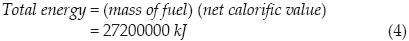
The energy to fire one brick is calculated with the following equation:

Therefore, the energy to fire a brick obtained from La Solana is 2365 kJ (657 Wh); however, this value will to some extent depend on the kind of clay, the moisture content of 'green' bricks, the type of fuel used, and the design of the kiln. Differential scanning calorimetry experiments carried out on various 0.5–g samples of raw brick material gave results between 614 kJ/kg and 780 kJ/kg, for heating from room temperature to 700°C (data not shown), these values are compatible with the value of 985.4 kJ/kg calculated above, which refers to heating up to 1000°C.
Solar radiation throughout a day in Querétaro City
The average daily direct normal radiation in Querétaro City (20.58°N, 100.37°W) is 6680 Wh/m2/day (NASA. Atmospheric Science Data Center, 2009).
Heliostat dimensions
To calculate the dimensions of the heliostat to fire 10 clay bricks to temperatures between 950°C and 1050°C the following methodology is used. First the energy flux reflected from the parabolic concentrator and intercepted by the prismatic cavity during a solar day (8 hours) is calculated with the following equation:

The rate of net energy transfer to fire 10 bricks is calculated with the following equation:

The heat loss rate of the rectangular–prism cavity is calculated with equation (8):

The radiative loss of thermal energy occurs mainly through the orifice of the prismatic cavity; it is calculated with equation (9), considering that Aorif = 0.115 x 0.115 m, σ = 5.67 x 10⁻⁸ W/m2K4, εorif = 1, Trpc = 1273.16 K, Tamb = 298.16 K:

The rate of thermal energy loss by conduction and convection is calculated with the following equation:

where

Rtotal is 14.24 K/W, considering that the values for hrpc–int and hffc–ext used in this equation (5 W/m2·K and 40 W/m2·K) were estimated from the ranges given by Çengel (2004a) for free convection of gases and forced gas convection, respectively. The thermal conductivity values are krpc = 27.4 W/m·K (High Temp Metals, 2009), kair = 0.026 W/m·K (Çengel, 2004c), kbrick = 0.64 W/m·K (determined experimentally by the authors), krefractory = 0.6 W/m·K (Çengel, 2004c), kblanket = 0.4 W/m·K (Thermal Ceramics, 2009), ksheet cover = 15 W/m·K (Çengel, 2004c). Area values are Arpc,int = 0.045 m2, Arpc,ext = 0.057 m2, Afc,int = 0.449 m2, Ablanket = 0.696 m2, Asheet cover = 0.797 m2. Thickness values are Lrpc = 0.015 m, Lair,1 = 0.01 m, Lair,2 = 0.093 m, Lbrick = 0.07 m, Lrefractory=0.1 m, Lblanket = 0.1 m, Lsheet cover = 0.001 m.
The arbitrariness inherent in the estimate of hrpc–int and hfc–ext will not significantly affect the value finally calculated for the total rate of heat loss because, as will be seen below in equation (8), losses by convection are very much lower than the radiative energy loss.
With this, the rate of heat loss calculated from equation (10) becomes  loss,c = 68.45 W.
As can be seen by comparison with the rate of radiative heat loss (1964.28 W), already calculated from equation (9), by far the largest part of the heat loss occurs by radiation.
The rate of thermal energy loss is calculated from equation (8) of loss = 2032.73 W.
Therefore, int is obtained from equation (6) as int = 2853.89 W.
The equations given by Stine and Geyer (2001) are used to calculate the heliostat dimensions. To this end, the parabolic concentrator is considered divided into 21 strips, each one covering an angle of ΔΨ = 0.038 radians:

The total radiant flux reflected from a given strip is calculated with the equation given by Stine and Geyer (2001), considering ρc = 0.9, αrpc= 0.9:

To calculate Γ, we consider the following. To ensure that 95 percent of all possible energy is captured, the number of standard deviations must be n = 4. The standard deviation considers slope errors of the heliostat surface, tracking errors, errors in the alignment of the off–axis parabolic concentrator, the non–specular reflectance of the heliostat and the off–axis parabolic concentrator, and the angular width of the sun.
The fraction of reflected flux which will be intercepted by the prismatic cavity is calculated as follows (Abramowite et al., 1972; Stine et al., 2001):

where


with r = 0.2316419; b1 = 0.319381530; b2 = –0.356563782; b3 = 1.781477937; b4 = –1.821255978; and b5 = 1.330274429.
Substituting the preceding parameters into equations (14) to (18), and setting n at 4, we obtain Γ,= 0.95.
Therefore,

Finally, the heliostat area is calculated considering that Ib = 6680 Wh/m2/day = Gb = 835 W/m2 (NASA. Atmospheric Science Data Center, 2009), ρh = 0.9, and θi= 44.25° (average incident angle in the worst case, June 21):

To obtain the heliostat area the following equation is used:

Thus, the heliostat area required to fire 10 bricks is 9 m2.
Internal temperature for the firing chamber
To consider whether the proposed arrangement could deliver the requisite high temperature in the solar oven under the local conditions, we measured the direct solar radiation data normal irradiance with a pyrheliometer (The Eppley Laboratory, Model NIP) on a sun tracker (The Eppley Laboratory, Model ST–1) throughout a summer solstice day (June 21, 2006), which from geometric considerations would be the most unfavorable date for our planned system, and then we calculated the intercepted radiation flux int corresponding to these data. The results are summarized in table 2.

From the calculated int data, the external temperature of the firing chamber is computed with the following equation, considering that εfc = 0.9, Afc,ext = 4.43 m2, hfc–int = 5 W/m2K, hfc–ext = 40 W/m2K, Ts = 293.16 K, and Tamb= 298.16 K:

where

Rtotal is 0.143 K/W, considering that Rconv,fc–int = 0.045 K/W, Rrefractory = 0.038 K/W, = 0.055 K/W, Rblanket = 0.055 K/W, Rsheet cover = 0.000015 K/W, Rconv,fc–ext= 0.006 K/W.
From this, we obtain the external temperature of the firing chamber Tfc for each hour.
From the values for the external temperature thus obtained, the internal temperature of the firing chamber is calculated with equation (23), considering εrpc = 0.9, Aorif = 0.013 m2, Frpc,fc = 1, hrpc–int = 5 W/m2K, mcb = 25.92 kg (10 bricks), and Cp = 1067 J/kgK:

where

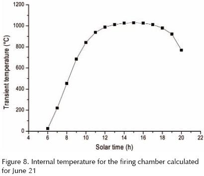
The internal temperature of the firing chamber in the transient state T(t) is determined with the following equation (Çengel, 2004b):

where the exponent b is determined with equation (26), considering, ρcb = 1922 kg/m3, Vfc = 0.22 m3:

The reciprocal of b is the time constant:

Figure 8 shows the calculated values for the internal temperature of the firing chamber in the transient state throughout June 21.
Off–axis parabolic concentrator dimensions
Ray–tracing diagrams were drawn to determine the size of the solar spot for the system heliostat + parabolic concentrator, on the orifice of the prismatic cavity, and the dimensions of the parabolic concentrator aperture. In these ray–tracing diagrams, the angular dimension of the solar disk (10 milliradians in diameter) was taken into account.
To design the parabolic concentrator, we worked with different focal lengths (0.5, 0.75, 1, 1.25 and 2 m) to find the smallest solar–spot size on the aperture of the rectangular–prism cavity. The best result was obtained for a focal length of 1 m. Table 3 shows the solar spot size for different focal lengths of the parabolic concentrator. For the focal length of 1 m, figure 9 shows the ray–tracing diagram for March 21, and table 4 shows the solar–spot size on the aperture of the rectangular–prism cavity for different days of the year, when the firing chamber is fixed or when it is moved to find the smallest spot size.


The parabolic concentrator aperture is 1.58 m (figure 9b), this dimension was determined selecting the day with the smallest angle of incidence of beam radiation on the heliostat (December 21), when the maximum spot size produced by the heliostat is intercepted by the parabolic concentrator.
Results and discussion
Pieces of 'green' clay brick obtained at La Solana were fired in a laboratory furnace to 800 °C, 850 °C, 900 °C, 950 °C, 1000 °C, 1050 °C, and 1100°C; the properties of the clay bricks baked in the muffle oven are shown in table 5. As a result of these tests the appropriate firing temperature was found to be between 950°C and 1050°C. Lower baking temperatures resulted in bricks with an unacceptably low compression strength and high water absorption.
Calculations were performed to determine the dimensions of the heliostat and the parabolic concentrator, for a solar furnace with a capacity to fire 10 bricks simultaneously to temperatures between 950°C and 1050°C.
In these calculations, anodized aluminum was considered as the reflective material, for both the heliostat and the parabolic concentrator, as this material has a specular reflectance of around 0.9, for wavelengths between 300 nm and 2500 nm.
The required heliostat area was calculated at 9 m2, considering that the energy to fire a brick obtained from La Solana is 657 Wh, and the average daily direct normal radiation in Querétaro City is 6680 Wh/m2/day. The heliostat design includes nine mirrors, each with dimensions of 1 m × 1 m, arranged in three rows and three columns. A rotation–elevation sun tracking system is used because it produces fewer aberrations than an azimuth–elevation system (Chen et al., 2004); therefore, the heat flow is more uniform in time. Moreover, only M + N = six motors are required with the rotation–elevation tracking system, two for primary tracking and four for secondary tracking.
An off–axis parabolic concentrator with an aperture of 1.58 m and a focal length of 1 m is used. This kind of concentrator avoids any shading of the concentrator surface by the firing chamber, as happens with the axial concentrators. The system consisting of heliostat plus parabolic concentrator produces a spot size of 0.13 to 0.24 m on the firing chamber. A larger prototype can be designed to fire 110 clay bricks per day. With daily use it would then be possible to obtain 3300 bricks per month; the area of the heliostat was calculated using equations (6) to (20), the result is 46.63 m2, thus, the heliostat area required to fire 110 bricks is 49 m2. The heliostat design includes 49 mirrors, each with dimensions of 1 x 1 m, arranged in seven rows and seven columns; 28 motors are required with the rotation–elevation tracking system for the two heliostats, four for primary tracking and 24 for secondary tracking. An off–axis parabolic concentrator with an aperture of 1.58 m and focal length of 1 m is required, as are two firing chambers, each with inner dimensions of 0.51 x 0.67 x 1.48 m and outer dimensions of 0.81 x 0.97 x 1.58 m; while one chamber is in the firing process, the other one is in the cooling process. Equations (21) to (26) are used to obtain the time constant (1/b = 28770.04 s = 7.99 h) and the time to obtain 1000°C for 110 bricks (t = 9 hours).
It should be emphasized that these considerations of scale are based on calculations, using equations (6) through (20), not on experimental data. The same holds true of the earlier consideration of a furnace to bake 10 bricks at a time.
Nomenclature

Conclusions
With the characterization of material properties, new and better construction materials are being developed every day (Custodio et al., 2005). Nevertheless, fired clay bricks will still be used on a very large scale in the future. The use of solar furnaces for clay–brick firing would avoid the air and soil pollution caused by the present cottage–industry brick production methods, which are based on the combustion of domestic or industrial wastes. The use of solar energy will entail a cost reduction for the bricks because it will obviate the need to purchase fuels for the firing process.
The sun–tracking system calculates the primary and the secondary tracking of the heliostat, in dependence of solar time.
The quality of bricks should improve due to the fact that the heat inside the firing chamber is uniform, in contrast to the situation which obtains with the traditional kilns.
Design and construction of the prototype was carried out for 10 bricks; however, a larger prototype can be designed to fire 110 bricks per day. The solar furnace can be used daily as long as there is a sufficient sunshine quality, which would provide for the firing of maximally 3300 bricks per month.
Acknowledgments
We express our gratitude to SIP–IPN (Project numbers 20050945, 20060844, 20070731, and 20080064), CONCYTEQ–IPN (Funding Cycle 2008), and ASA de México for their support in the development of this project.
References
Abramowitz M., Stegun I.A. Handbook of Mathematical Functions with Formulas, Graphs and Mathematical Tables, 10th printing, Washington, D.C. National Bureau of Standards, 1972, pp. 932. [ Links ]
Alpert D.J., Mancini T.R., Houser R.M., Grossman J.W., Schissel P., Carasso M., Jorgensen G., Scheve M. Solar Concentrator Development in the Unites States. Solar Energy Materials, 24:307–319. 1991. [ Links ]
Chen Y.T., Chong K.K., Bligh T.P., Chen L.C., Yunus J., Kannan K.S., Lim B.H., Lim C.S., Alias M.A., Bidin N., Aliman O., Salehan S., Shk. Abd. Rezan S.A.H., Tam C.M., Tan K.K. Non–Imaging, Focusing Heliostat. Solar Energy, 71(3):155–164. 2001. [ Links ]
Chen Y.T., Chong K.K., Lim C.S., Lim B.H., Tan K.K., Aliman O., Bligh T.P., Tan B.K., Ismail G. Report of the First Prototype of Non–Imaging Focusing Heliostat and its Application in High Temperature Solar Furnace. Solar Energy, 72(6):531–544. 2002. [ Links ]
Chen Y.T., Kribus A., Lim B.H., Lim C.S., Chong K.K., Karni J., Buck R., Pfahl A., Bligh T.P. Comparison of Two Sun Tracking Methods in the Application of a Heliostat Field. Journal of Solar Energy Engineering, 126:638–644. February 2004. ISSN: 0199–6231. [ Links ]
Chen Y.T., Lim B.H., Lim C.S. Off–Axis Aberration Correction Surface in Solar Energy Application. Solar Energy, 80:268–271. 2006. [ Links ]
Çengel Y.A. Transferencia de calor, 2nd edition, Mexico, DF, McGraw Hill, 2004a, p. 26. [ Links ]
Çengel Y.A. Transferencia de calor, 2nd edition, Mexico, DF, McGraw Hill, 2004b, pp. 210–211. [ Links ]
Çengel Y.A. Transferencia de calor, 2nd edition, Mexico DF, McGraw Hill, 2004c, pp. 725–736. [ Links ]
Custodio–García E., Sebastian P.J., Campos–Alvarez J., Treviño–Palacios C.G., Zarate E.A., Córdova Q.A., De la O–León H. Solar Conduction Heat Transfer in Fired Clay Bricks. Solar Energy Materials & Solar Cells, 88:169–178. 2005. [ Links ]
Dirección General de Normas. Norma Mexicana NMX–C–036–1983, Industria de la construcción–ladrillos, bloques y adoquines de concreto–resistencia a la compresión–métodos de prueba. Naucalpan de Juárez, Estado de México, Secretaría de Comercio y Fomento Industrial, 1983, Mexico. [ Links ]
Dirección General de Normas. Norma Mexicana NMX–C–037–1986. Industria de la construcción–concreto–bloques, ladrillos o tabiques y tabicones de concreto–determinación de la absorción de agua, México, DF, Secretaría de Comercio y Fomento Industrial, 1986, Mexico. [ Links ]
Fernández–Reche J., Cañadas I., Sánchez M., Ballestrín J., Yebra L., Monterreal R., Rodríguez J., García G., Alonso M., Chenlo F. PSA Solar Furnace: A Facility for Testing PV Cells Under Concentrated Solar Radiation. Solar Energy Materials & Solar Cells, 90:2480–2488. 2006. [ Links ]
Goswami D.Y., Kreith F., Kreider J.F. Principles of Solar Engineering, 2nd edition, Philadelphia, PA. Taylor & Francis, 2000, pp. 6. [ Links ]
Hernandez D., Olalde G. Solar Experimental Methods for Observing Melting Plateaux and Associated Temperature Measurements for Refractory Oxides from 2000 to 3000°C. Journal of the European Ceramic Society, 26:1043–1049. 2006. [ Links ]
High Temp Metals. Hastelloy X Technical Data. High Temp Metals [on line]. 2009 [consultation date February 27, 2009]. Available on: http://www.hightempmetals.com/techdata/hitempHastX–data.php [ Links ]
Jiménez de Salas J.A., De Justo–Alpañes J.L. Geotecnia y cimientos I. Propiedades de los suelos y de las rocas, 2nd edition, Rueda, 1975. [ Links ]
Kalogirou S. Recent Patents in Solar Energy Collectors and Applications. Recent Patents on Engineering, 1: 23–33.2007. [ Links ]
Lewandowski A., Bingham C., O'Gallagher J., Winston R., Sagie D. Performance Characterization of the SERI High–Flux Solar Furnace. Solar Energy Materials, 24:550–563. 1991. [ Links ]
Mason K. How to Measure the Energy Used to Fire Clay Bricks, Rugby, UK, Practical Action, Intermediate Technology Development Group, Ltd., 1998. [ Links ]
NASA. Atmospheric Science Data Center. NASA Surface Meteorology and Solar Energy–Available Tables. NASA [on line]. 2009 [consultation date February 3, 2009]. Available on: http://eosweb.larc.nasa.gov/sse/ [ Links ]
Pancotti L. Optical Simulation Model for Flat Mirror Concentrators, Solar Energy Materials & Solar Cells, 91:551–559. 2007. [ Links ]
Ries H., Schubnell M. The Optics of a Two–Stage Solar Furnace. Solar Energy Materials, 21:213–217. 1990. [ Links ]
Riskiev T.T., Suleimanov S.K.H. Double Mirror Polyheliostat Solar Furnace of 1000 kW Thermal Power. Solar Energy Materials, 24:625–632. 1991. [ Links ]
Scheffler W. Introduction to the Revolutionary Design of Scheffler Reflectors. SCIs International Solar Cooker Conference (2006, Granada, Spain). [ Links ]
Stine W.B., Geyer M. Power from the Sun [on line]. USA. Power from the Sun, 2001 [consultation date January 15, 2009]. Available on: http://www.powerfromthesun.net/book.htm [ Links ]
Thermal Ceramics. Technical Datasheets. Thermal Ceramics [on line]. 2009 [consultation date February 27, 2009]. Available on: http://www.thermalceramics.com/datasheets.asp?filter=all&filter2=Blanket®ion= [ Links ]
About the authors
Gabriel Villeda–Muñoz. Mechanical engineer's degree from the Escuela Superior de Ingeniería Mecánica y Eléctrica del Instituto Politécnico Nacional (ESIME–IPN, School of Mechanical and Electrical Engineering of the National Politechnic Institute), Campus Culhuacan (2000), and Master's degree in Systems Engineering from the same Institution, Campus Zacatenco (2004). At present he is a doctoral student in the advanced technology program at CICATA–IPN Querétaro. Areas of expertise: Alternative energies, high–temperature solar furnaces.
Alejandro Castañeda–Miranda. Engineer's degree in Communications and Electronics from the University of Zacatecas (1995). Master's degree in Advanced Technology from CICATA–IPN Legaria (2003). Doctoral degree in Engineering with specialty in mechatronics and instrumentation from the Autonomous University of Querétaro (2004). Postdoctoral studies in the area of materials science with specialty in materials at CINVESTAV–IPN Querétaro. At present he is a research professor in mechatronics and instrumentation at the Polytechnical University of Querétaro. Areas of expertise: electronics, automation, mechatronics, instrumentation, artificial neural networks, biomechatronics embedded systems, image processing, and three–dimensional reconstruction with precision lasers.
Pless R.C. Doctoral degree in Chemistry from Northwestern University, Evanston, Illinois, USA. After postdoctoral work at the Johns Hopkins University, Baltimore, Maryland, and at the Polish Academy of Sciences in Warsaw, he joined the Ohio State University in Columbus, Ohio, as chemistry professor. He later moved to Life Technologies, Inc., in the state of Maryland, to head the Product Development Group. He has been research professor at CICATA–IPN since 1997, initially in Mexico City and later in Querétaro. Areas of expertise: alternative energies, chemical and physical changes in the maize kernel during alkaline cooking, chemistry of nucleic acids. At present, he is a member of the National System of Researchers, level II.
José Trinidad Vega–Durán. Bachelor of Solid State Physics by ESFM–IPN (1992). Doctoral degree in Optics from the University of Guanajuato (2000). After that, he was research professor in advanced technology at CICATA–IPN Querétaro, working in his areas of expertise: optical and electrical metrology, optoelectronic, optical properties of materials, and industrial applications of lasers. Dr. Vega–Durán died at the conclusion of the present work. This article is dedicated to his memory.
Jorge Pineda–Piñón. Researcher–professor at CICATA Querétaro since January 2005. Master's degree in Architecture from the School of Engineering and Architecture of the National Polytechnic Institute and Doctoral degree in Engineering from the Autonomous University of Querétaro. Areas of expertise: construction materials, high–temperature solar furnaces, and bioclimatic houses. Professional area: designer and builder of residential homes. Professional experience: He was technical subdirector of the Technological Research Center 1 "Walter Cross Buchanan" of the Instituto Politécnico Nacional. Publications: Six published book articles, one published paper in a scientific journal, two papers under review by scientific journals, and one patent in progress. At present he is a member of the National System of Researchers, level I.

