


Servicios Personalizados
Revista
Articulo
 Inglés (pdf)
 Artículo en XML
 Referencias del artículo
 Enviar artículo por email
Indicadores
-
 Citado por SciELO
 -
 Accesos
Links relacionados
-
 Similares en
SciELO
Similares en
SciELO
Compartir

 Permalink
Ingeniería, investigación y tecnología
versión On-line ISSN 2594-0732versión impresa ISSN 1405-7743
Ing. invest. y tecnol. vol.12 no.1 Ciudad de México ene./mar. 2011
Digitally Addressable Digital Dimming Electronic Ballast Based on CAN Bus
Balastro electrónico digital con control de intensidad luminosa direccionado digitalmente basado en bus CAN
Rodríguez–Segura E.1, Díaz–Carmona J.2, Hurtado–Chávez L.3, Vázquez–Nava N.4 and Correa–Gómez J.5
1 Instituto Tecnológico de Celaya, Celaya Gto. E–mails: elias@itc.mx
2 Instituto Tecnológico de Celaya, Celaya Gto. E–mails: jdiaz@itc.mx
3 Instituto Tecnológico de Celaya, Celaya Gto. E–mails: jjhhc@hotmail.com
4 Instituto Tecnológico de Celaya, Celaya Gto. E–mails: nvazquez@itc.mx
5 Instituto Tecnológico de Morelia, Morelia Mich. E–mails: javrcorrea@hotmail.com
Información del artículo: Recibido: septiembre de 2007.
Reevaluado: junio de 2009 y enero de 2010.
Aceptado: abril de 2010.
Abstract
This paper describes the design and implementation of a new digital dimming electronic ballast with the capability of being remotely controlled in a digital way, this is achieved through a novel lighting network based on Controller Area Network (CAN) bus standard. The proposed ballast was designed to drive a T5, 28 Watts fluorescent lamp. The proposed functional performance was tested using an implemented lighting network system based on CAN 2.0A bus specification. The defined lighting network functions include dimming, turning on and off, and fault condition detection. The network control is made with a lighting system software in a personal computer (PC) through one specific CAN node, being able to address up to 2047 individually controllable ballasts. According to the obtained results the proposed digital dimming electronic ballast performed the established functions successfully, meeting C class of the International Electrotechnical Commission (IEC) standard. The resulting system consists of a novel fully functional CAN bus lighting network with a reliable two wire remote control. Applications for this CAN Bus lighting network include lighting systems focused on design issues like lamp dimming control for electrical energy consumption savings and efficient lamp maintenance. Such application areas cover building lighting management, precision lighting effects, and studio lighting.
Keywords: electronic ballast, lighting control, network interfaces, communication standards, CAN, microcontroller application.
Resumen
Este artículo describe el diseño e implementación de un nuevo balastro electrónico digital con variación de intensidad luminosa controlado digitalmente a distancia, mediante una novedosa red de iluminación basada en el estándar Bus CAN (Controller Area Network). El balastro propuesto opera con una lámpara fluorescente del tipo T5, 28 Watts, el cual se implementó en una red de iluminación basada en la especificación CAN 2.0A. Se incluyeron funciones de variación de intensidad luminosa, apagado, encendido y detección de condición de fallo. El control de la red se realiza con un programa en una computadora personal (PC) a través de un nodo CAN específico, con el cual es posible controlar individualmente hasta un máximo de 2047 balastros. De acuerdo con los resultados obtenidos el balastro electrónico propuesto realiza exitosamente las funciones establecidas, cumpliendo con el estándar internacional clase C de International Electrotechnical Commission (IEC), lo cual permite la implementación de una red de iluminación CAN novedosa completamente funcional con control remoto confiable. Las aplicaciones para esta red de iluminación CAN incluyen sistemas de iluminación enfocados al control de intensidad luminosa para ahorro en el consumo de energía eléctrica y mantenimiento eficiente de lámparas. Tales áreas de aplicación cubren sistemas de mantenimiento de lámparas en edificios, efectos luminosos de precisión e iluminación de estudios.
Descriptores: balastros electrónicos, control de iluminación, interfaces de redes, estándares de comunicación, CAN, aplicación de microcontroladores.
Introduction
The use of electronic ballasts to drive fluorescent lamps has been increased mainly due to the advantages they offer compared with electromagnetic ballasts. In early proposals the ballast design goal was focused to provide just enough light for visual tasks on specific areas. Nowadays, the electronic ballast design goal has been extended to achieve more efficient systems including design issues like: low harmonic distortion, high power factor and light dimming, reducing in this way electric energy consumption. Another important ballast feature is the controllability, which is the ballast capability for sending and receiving information through some reliable network communication protocol, allowing a remote control of a complete lighting environment.
Currently, there are available electronic ballasts designs meeting the mentioned features. Some controllable ballasts use an analog 1–10 VDC signal to perform just lighting intensity control, while electronic ballasts, based on digital control, are capable to feature more complex tasks, such as lighting dimming with a dedicated digital power controller (In–Hwan, 2004), and remote control based on lighting network communication protocols. Most of the existing lighting network systems are based on a master–slave scheme such as the proposed in (Marchesan et al., 2004) and (Alonso et al., 2000), where the power line is used as transmission media. One of the most commercially available lighting network based on a master–slave scheme is the Digital Addressable Lighting Interface (DALI) (Contenti et al., 2002), (Hein, 2001), that performs individually electronic ballast control.
DALI is a standard lighting system protocol defined by the Europe lighting industry (DALI, 2001), allowing digital communication in electronic ballasts systems. This standard is an asynchronous serial protocol using a two–wire differential signal. A DALI lighting network is composed by one DALI Control node and up to sixty four ballast nodes. The communication is based on a master–slave scheme without collision detection and avoidance features, where DALI Control node sends commands and data to any ballast node (Forward Message Frame) and each ballast node sends data to DALI Control node (Backward Message Frame). By this way it is not possible the information transfer between two ballasts without DALI Control node intervention (Hein, 2001). Due to the lack of integration presented in DALI, the use of external global systems has to be employed. An example of such global systems is the Integrated Building Environmental Communications System (IBECS), which is a communication network that allows most building equipment loads, including individual light fixtures, operable window blinds, motors and environmental sensors, be controlled and monitored by an Ethernet network (Rubinstein et al., 2000), (Rubinstein et al., 2003).
Most of the lighting industry efforts for the development of advanced lighting systems, commonly using environmental sensors for automatic light control, are focused to meet two main design goals: to achieve electrical energy consumption savings and to increase work productivity by providing control over the workplace light.
The Controller Area Network (CAN) is an asynchronous serial communication protocol for microcontrollers networks, which is based on carrier sense multiple access/collision detection (CSMA/CD) and supports distributed real–time control (bit rate up to 1Mbps) with a very high level of security (Bosch,1991). CAN communication protocol is based on a distributed scheme, there is no control unit, allowing a direct data transfer between any two nodes without a master node mediation. The CAN protocol was initially created in mid–1980s as a robust solution for automotive applications, and since 1990 CAN has become a reality in automotive applications as well as in industrial control design, (Lawrenz, 1997). Standard ISO 11898 defines CAN bus as a two wire reliable protocol for high–speed applications (Microchip, 2002). A standard CAN bus configuration is implemented with CAN nodes composed by the modules: microcontroller, CAN controller and CAN transceiver, as shown in figure 1.
This paper describes the design and implementation of a digital dimming electronic ballast capable of being part of a novel CAN bus controlled lighting network. In next section the development of a CAN bus lighting network system, using the proposed ballast, is shown. In following two sections the proposed digital electronic ballast and the developed lighting system software are described. Finally experimental results and conclusions are presented in last two sections.
Can bus lighting network system
The general block diagram of the lighting network is shown in figure 2. A personal computer (PC) performs the system control through one specific CAN network node (CAN node 0). The CAN 2.0A specification is used, thus the network system allows a maximum of 2047 digital dimming electronic ballasts be individually controlled. The defined network functions include: dimming, turning on/off, and fault condition warning such as lamp removal, end of lamp life or broken tube. The network communication is done through the two differential signals: CANH and CANL, in this way a remote two–wire control is achieved.
Each ballast in the CAN network has an individual and unique assigned identifier. This identifier is an eleven bits number in the range from 0x01 to 0x7FF. The addressing range might be divided to achieve other functions, such as lighting group control, where each ballast would have both individual and group identifiers. Also some identifiers would be reserved for special purpose features with functions like sending information from local environment sensors through the lighting network.
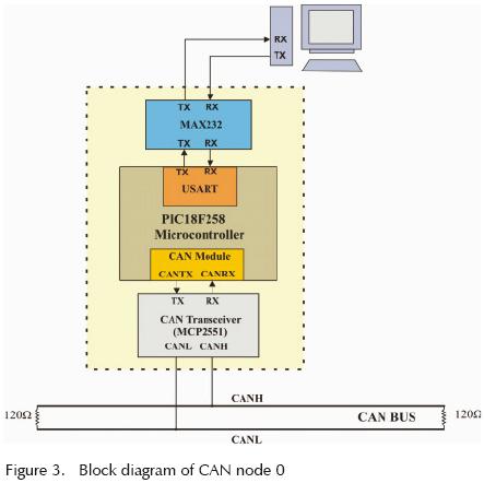
The PC control is made through the CAN node 0, identifier 0x000, which performs either PC–ballast or ballast–PC communication. For first case one specified ballast is requested to execute an instruction, dimming for instance, in two phases. First the instruction is sent through the PC serial port to CAN node 0 as a four bytes code (two bytes for ballast identifier, one for instruction code and one for dimming level). In second phase the CAN node 0 transmits the instruction code as a CAN data frame to the addressed ballast, whose identifier field includes the eleven bits identifier of the specific ballast and the data field includes the instruction code. In the same way two phases are done in a ballast–PC communication where a specific ballast message is received by the PC, such as fault condition. In first phase a CAN data frame is sent by the specific ballast to the CAN node 0, including as identifier field its 11 bits identifier and a fault message code as data field. In second phase CAN node 0 sends the received fault message code and ballast identifier, through the serial port, to the PC in a 3 byte format (two bytes for ballast identifier and one for the message code). When the fault message code is received by the PC the sys–tern control software shows a warning fault condition to the user in the PC screen, indicating both the fault type and the ballast identifier having the fault condition. In the same way more ballast local conditions messages might be added to the system (up to 256), for instance environmental sensor data (occupancy, daylight, temperature, etc.). The CAN node 0 block diagram is illustrated in figure 3, which is composed by: CAN transceiver (MCP2551), microcontroller with on chip CAN driver and serial ports (Microchip PIC18F258), and one RS232 serial interface (MAX232).
The CAN bus standard collision detection and avoidance features allow information transfer between any two ballasts, or between one ballast and several ballasts, without PC or node 0 mediation, in this way implementation of additional control features is possible, such as the required ones in an intelligent lighting system (Miki et al., 2004).
Electronic ballast design
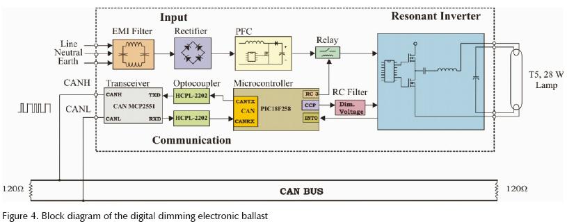
The block diagram of the proposed digital electronic ballast is shown in figure 4. The overall structure is composed of three main components: the input stage, the resonant inverter stage and the digital communication stage.
The conventional front–end off–line converters typically consist of a full bridge rectifier (FBR), a capacitor filter, and one unregulated DC bus. For such converters the current drawn from the AC mains is a series of narrow pulses whose amplitude is five to ten times higher than the resulting DC value; a lot of drawbacks result from that: high semiconductor current stress, high RMS current drawn from the line, distortion of the AC line voltage, overcurrents in the neutral line in three–phase systems and, after all, a poor utilization of the power system energy capability.
The use of a Power Factor Correction (PFC) pre–regulator, located between the FBR and the filter capacitor, allows drawing from the mains a quasi–sinusoidal current in–phase with the line voltage. In this way the resulting power factor approaches to unity and the drawbacks described above are reduced.
The ballast input stage is composed by an EMI filter, a FBR and a DC/DC boost converter. This section is based on the integrated circuit L6561, as shown in figure 5, which controls the PFC preregulator using the transition mode technique, this approach consists of a Zero Current Turn–on system, switching with variable frequency and duty cycle. Given the desired specifications the main design issues in this mode approach are: boost inductor and bulk capacitor values computation and switching transistors selection. The input stage design specifications are: input line voltage in the range of 90 to 140 Vrms, rated output power of 35W, minimum switching frequency of 35KHz and a regulated DC output voltage of 350 VDC.
The boost inductor design involves several parameters and different approaches may be used. In order to ensure a correct transition mode operation the inductance value (L) is usually computed such that the minimum switching frequency is greater than the maximum frequency of the internal starter. The inductor value is given as:
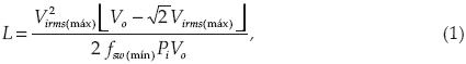
where Virms(máx) is the maximum input voltage, V0 is the desired DC output voltage, fsw(min) is the minimum switching frequency and Pi is the input power value. An inductance value of 2.18 mH is obtained for the design parameters values: virms(máx) = 140 V, V0 = 350V, fsw(min) = 35 KHz and Pi = 55.55 W.
The minimum value of the output bulk capacitor (C7) depends on the DC output voltage V0, the tolerated voltage ripple ΔV0, and the output power P0:

a value of C7 = 9.47 μF is obtained for P0 = 50 W, f = 120 Hz and ΔV0 = 10. A commercial value of 22 μF was used, as shown in figure 5.
The switching MOSFET transistor is chosen mainly by its drain–source on resistance, RDSon. Since the breakdown voltage is fixed just by the output voltage then the transistor selection depends on the specified over–voltage, the safety margin and the output power. The MOSFET power dissipation is given by the conduction and switching losses. The conduction power loss is given by:

Due to the transition mode operation the switching losses occur only at transistion falling edges of the switching transistor:

According to the computed transistor power dissipation the selection of the transistor IRF840 to perform the switching task fulfills the required specifications.
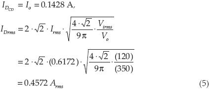
The boost freewheeling diode D7 must have a fast recovery time, which is met by the MUR1560. The value of its DC and RMS current, useful for losses computation, are given respectively by:
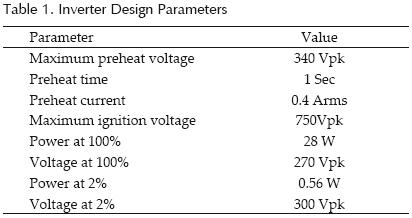
The resonant inverter stage, shown in figure 6, was designed to drive a T5, 28 Watts fluorescent lamp type allowing a current mode preheat starting. The design parameters to drive the lamp are shown in the table I. This stage is performed by the International Rectifier integrated circuit IR21592, which has a dimming interface for analog lamp power control. The dimming is controlled by a DC variable voltage in the range of 0.5 to 5.0 volts applied in the Dim pin (International, 2005). In the resonant inverter stage a fault condition detection circuit is proposed, as shown in figure 6, which is implemented with the operational amplifier LM358 operating as comparator. The comparison is made between a fixed internal voltage reference and the voltage on SD pin of IR21592. When the lamp tube is removed or broken a fault condition occurs and the IR21592 enters in fault mode turning off its driver outputs, HO and LO, protecting in this way the ballast. A rising voltage transition is obtained at the comparator output when the fault condition occurs. Such transition activates the microcontroller enabled external interrupt INT0, whose interrupt service routine sends a data frame to the CAN node 0 through the CAN bus network, including the ballast identifier and the fault message code. If the lamp is replaced, the sequence process (preheat, ignition and dimming) takes place again.
The dimming voltage is controlled remotely through the CAN bus network. This level is transmited by CAN node 0 as an 8 bits number representing the duty cycle value of a PWM signal with a fixed frequency of 40 kHz, which is generated within the Compare/Capture/PWM (CCP) module of the Microchip PIC18F258 microcontroller. The dimming level voltage is obtained from the average voltage of the generated PWM signal, through RC filtering, as shown in figure 7.
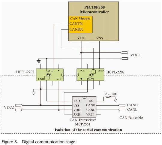
The digital communication stage is the interface between the digital electronic ballast and the CAN network. This stage can be implemented using any Full CAN controller, the proposed prototype communication stage uses the on–chip CAN controller of Microchip PIC18F258 microcontroller, (Microchip, 2004), and the CAN transceiver MCP2551, which supports up to 1 Mbps transfer rate meeting the ISO–11898 standard physical layer requirements (Microchip, 2003). The CAN controller bit rate was configured to 200K bps, allowing a maximum ballast to ballast distance of 250 meters. In order to avoid potential short circuit failures on the CAN network the ballast input stage is isolated with high speed Hewlett Packard optocouplers HCPL2202 (Hewlett, 1998), as shown in figure 8.
The proposed ballast includes one communication stage for each lamp allowing in this way individual control, which is useful in several applications such as generation of special lighting effects. Group controlling would be possible assigning two different identifier values to each one of the lamps within the group. One would be used for individual control and another for group control. If only group controlling is required the implementation might be done using only one communication stage per lamps group, having in this way all lamps the same identifier value.
The addition of a CAN–Ethernet interface as a CAN node in this lighting network would allow building area control. In this way several building areas might be controlled through the existing building Ethernet network.
When one specific ballast receives an instruction code from CAN node 0, the microcontroller decodes the function to be executed. In this way instruction codes were proposed to carry on the defined network functions. The dimming function code is 0x03 and the dimming level is given by a number in the range of 0 to 100 (0–100% dimming), which establishes the PWM duty cycle. The functions of turning on/off are coded as 0x081/0x082, when any of these functions is requested the microcontroller enables/disables the relay shown in figure 4. The use of one–byte length instruction codes allows up to 256 instructions be added to the proposed system, such as group dimming (broadcast), local environmental sensors reading, programmable sequences execution, etc.
Lighting system control software
The lighting system control software was developed in Visual Basic for Windows platform. The main window is a Graphical User Interface (GUI) with three available functions, as shown in figure 9. The serial communication between PC and CAN node 0 is opened with the Serial Link tab.
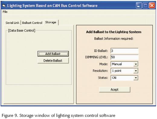
Once the serial communication is achieved, configuration and control functions of the lighting network are available. The network configuration is made with the Storage tab, shown in figure 9, where each one of the ballasts can be added or removed of the lighting network. Thee ballast addition is done by defining its initial setup, such as identifier, dimming level, dimming increasing step and status.
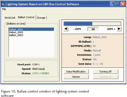
The lighting network control is featured in real time with the Ballast Control tab as shown in figure 10. This GUI allows the execution of the chosen function and status monitoring on specific ballast; the functions include dimming with a sliding bar, turning on and off buttons. In figure 10 is shown the case of a small lighting network with three ballasts, where one of the ballasts has a dimming level of 50%.
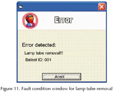
In the case of a fault condition is detected in one specific network ballast, the software pops up a warning window displaying the fault condition type and the identifier of the failed ballast. For instance the fault condition window for removal of lamp tube with identifier 001 is shown in figure 11. In this way the software allows the user to know what the problem is and where it is located; this is a good tool for fast maintenance response.
Experimental results
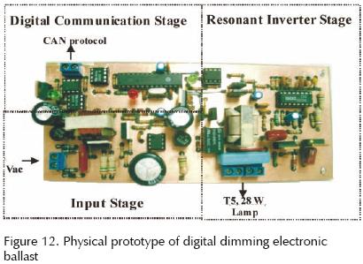
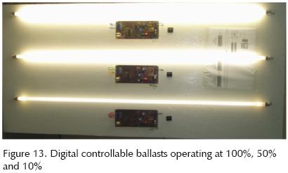
The experimental prototype of the proposed digital dimming electronic ballast is shown in figure 12. In order to test the ballast performance a lighting network was implemented with four CAN nodes, corresponding to three controllable ballasts and one CAN node 0. Several tests were made performing the defined lighting network functions successfully. In figure 13 is shown one example of individual dimming control with levels of 100%, 50% and 10% for each one of the T5, 28 W fluorescent lamps. The measured electronic ballast power factor was 0.96, and a total harmonic distortion of 12.36% was obtained, meeting the C class International Electrotechnical Commission (IEC) standard EN61000–3–2 specification.
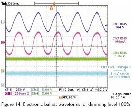
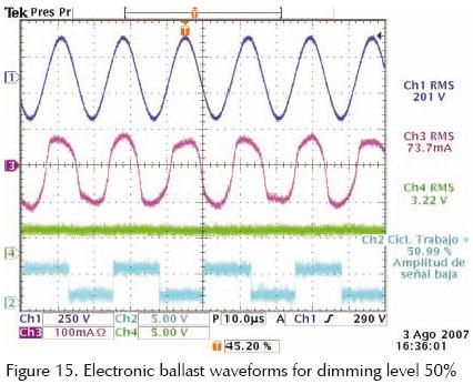
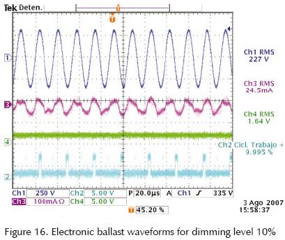
The lamp voltage and current in steady state, the DC voltage level and the PWM signals measured in the ballast with dimming levels of 100%, 50% and 10% are shown in figure 14–(15)–16, respectively. The DC voltage is used as dimming level voltage in IR21592 dimming pin. As can be observed this DC voltage level is directly proportional to the PWM duty cycle, which value is controlled through the lighting network. The lower PWM duty cycle, the lower ballast current peak value, meaning lower energy consumption. In this way the ballast energy consumption is remotely controlled through the CAN network according to the required dimming level. Several ballast to ballast distance tests were made, obtaining good CAN data transmission/reception for a maximum distance of 250 meters. Longer control distances may be achieved using smaller network bit rate.
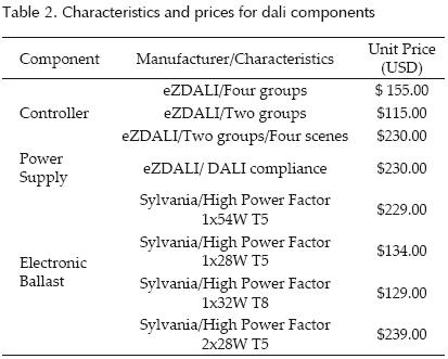
There are a few commercially available lighting networks protocols, among them DALI is one of the most widely used in developed countries. Main manufactures of DALI components are: Advanced Transformers, Beckhoff, Creative Lighting, Helvar, Lumernergy, Lutron, Leviton, Luella Enterprise, Lightolier, Osram–Sylvania, Tridonic Atco, Square D, Wattstopper, and Zumtobel.
Some commercially available DALI components, manufactures and current prices are shown in table 2. As it is noted DALI components prices are high. For instance the T5 1x28W DALI ballast price is $134 USD in contrast an electronic ballast without DALI support (high power factor and universal input voltage) has a price varying from $20 to $30 USD.
On the other hand the total prototype component cost of the implemented CAN bus ballast is approximately $45 USD, including its own DC power supply source and its communication interface. Such prototype cost might be notably reduced if it is produced in mass volume. It is important to highlight that an external power supply source is not required in the proposed ballast, as a DALI ballast does, since it is already included in the ballast itself through the auxiliary winding shown in figure 5. The proposed ballast has been designed taking into account efficiency and reliability factors. Some preliminary thermal, EMI and operating tests were performed to the prototype in the implemented CAN bus lighting network. Such tests might be extended in order to achieve a commercial product through a manufacturing process.
As a matter of costs comparison the individual and total prices of a DALI lighting network, meeting similar specifications than the one exposed in this paper, are presented in table 3. In the same way evaluated costs for the lighting network using the CAN bus ballast are detailed in table 4. Although an embedded network controller was not implemented a cost of $115 USD was estimated as enough for including a small controller board as CAN node 0, where lighting network controlling and monitoring might be performed by the user through a 4x16 LCD display and a small keyboard.
Conclusions
A fully functional digital dimming electronic ballast has been described, which main feature is its capability of being part of a novel and reliable lighting network based on CAN bus standard. Hence each one of the ballasts is digitally addressable through a distributed configuration scheme; this is without a master node mediation.
The proposed ballast was designed and implemented to drive in preheat mode a T5, 28 Watts fluorescent lamp. A CAN bus lighting network system, composed of three ballasts and one controller node, was tested with remote functions of dimming, turning on/off, and fault condition detection.
The lighting network control was made through one specific CAN node with a lighting system control software in a PC. Each one of the network ballasts performed the established functions successfully. According to the obtained results the proposed ballast presents low harmonic distortion, high power factor and a reliable controllability through a robust lighting network. The used CAN 2.0A specification allows the network lighting system may be expanded to a maximum of 2047 individually controllable ballasts. But the use of CAN 2.0B would increase the total number up to 229 network nodes.
The CAN bus introduction for controlling lighting networks, based on the proposed ballast, allows the performance of complex features. For instance a global lighting system can be designed for a complete control of lighting environment, where local environmental sensors (e.g. occupancy sensors, daylight sensors, etc.) and special functions (e.g. group dimming, predefined lighting sequences and scenes, etc.) might be integrated into the system.
The implemented ballast is an initial prototype, some improvements are considering for future work, such as board area reduction, digital control for resonant inverter stage and the addition of environmental sensors.
The proposed CAN lighting network might be expanded to be part of a global network like Ethernet/Internet, this would be possible using a commercial CAN–Ethernet bridge. In this way the proposed lighting network control might be added to a global system such as IBECS.
Applications for this CAN Bus lighting network include lighting systems with design goals: lamp dimming control for saving electrical energy consumption and efficient lamp maintenance. Those application areas might be building lighting management, precision lighting effects, and studio lighting.
References
Alonso J.M., Ribas J., Del Coz J., Calleja A., Corominas E., Rico–Secades M. Development of a Distributive Control Scheme for Fluorescent Lighting Based on LonWorks Technology. IEEE Transaction on Industrial Electronics, 47:1253–1262. 2000. [ Links ]
Bosch R. CAN Specification Version 2.0. Manual. 1991. [ Links ]
Contenti C., Ribarich T. Digitally Addressable DALI Dimming Ballast. Proceedings of Applied [ Links ]
Power Electronics Conference and Exposition 2002, Dallas Texas, USA, pp. 936–942. [ Links ]
DALI Activity Group. ZVEI–Division Luminaries, Manual, 2001 [on line]. Available on: http://www.dali–ag.org. [ Links ]
Hein P. DALI–A Digital Addressable Lighting Interface for Lighting Electronic. Proceedings of Industry Applications Conference 2001, Chicago Illinois, USA, pp. 901–905. [ Links ]
Hewlett Packard. HCPL2202 Very High CMR, Wide Vcc Logic Gate Optocoupler. Technical Data. 1998. [ Links ]
In–Hwan O., Rayabhari M., Zecchini M. A Full–Digital Dimming Ballast with a Digital Power Controller (DPC) for a Fluorescent Lamp. Proceedings of Industry Applications Conference 2004, San Jose California, USA, pp. 333–337. [ Links ]
International Rectifier. IR21592/IR21593 Dimming Ballast Control IC. Data Sheet. 2005. [ Links ]
Lawrenz W. CAN System Engineering from Theory to Practical Applications. New York. Springer. 1997. Pp. 26. [ Links ]
Marchesan T., Dernardin G., Silveira R., Campos A., Prado R. Development of a Control Fieldbus for HPS Electronic Ballasts Using Power Lines. Proceedings of 35th Annual IEEE Power Electronics Specialist Conference 2004, Aachen, Germany, pp. 3593–3596. [ Links ]
Microchip Technology. Application Note: A CAN Physical Layer Discussion. 2002. [ Links ]
Microchip Technology. MCP2551 High–Speed CAN Transceiver. Data Sheet. 2003. [ Links ]
Microchip Technology. Microcontroller PIC18FXX8. Data Sheet. 2004. [ Links ]
Miki M., Hiroyasu T., Imazato K. Proposal for an Intelligent Lighting System, and Verification of Control Method Effectiveness. Proceedings on IEEE Conference 2004 on Cybernetics and Intelligent Systems, Singapore, pp. 520–525. [ Links ]
Rubinstein F., Treado S., Pettler P. Standardizing Communication Between Lighting Control Devices: a Role for IEEE P1451. Proceedings. of Industry Applications Conference 2003. [ Links ]
Rubinstein F., Johnson S., Pettler P. IBECS: an Integrated Building Environmental Communications System–It's Not Your Father's Network. Proceedings of the American Council for an Energy Efficient Economy Summer Study on Energy Efficiency in Buildings. Pacific Grove California, USA, 2000, pp. 1–9. [ Links ]
ST Microelectronics. Application Note: L6561, Enhanced Transition Mode Power Factor Corrector. 2003. [ Links ]
About the authors
Elías Rodriguez–Segura. Received a B.S. degree in 1994 from the Universidad Autonoma Metropolitana (UAM–Azcapotzalco), México City, México, a M.S. degree in 1996 and a Ph.D. degrees in 1999 from the Centro Nacional de e Investigacion y Desarrollo Tecnologico (CENIDET), Cuernavaca Mor., Mexico, all in Electronics Engineering. He is currently a full time professor and researcher at the Electronics Engineering Department, Instituto Tecnológico de Celaya. His fields of interest include high–frequency power conversion, high–power–factor rectifiers, and electronic ballast. He is member of IEEE and National Researcher System (SNI) México.
Javier Díaz–Carmona. Received a B.S. degree in Electronics Engineering in 1990 from the Instituto Tecnológico de Celaya (ITC), Celaya Gto, Mexico, a M.S. degree in 1997 and a Doctor in Science degree in Electronics in 2003 from the Instituto Nacional de Astrofísica Optica y Electrónica (INAOE), Puebla, Mexico. Since 1991, he is faculty member at the Electronics Engineering Department, Instituto Tecnológico de Celaya, currently as full time professor and researcher. His research interests include digital signal processing, digital filter design techniques and microcontoller, DSP/ FPGA embedded systems applications. He is member of IEEE and National Researcher System (SNI) México.
Luis Hurtado–Chávez. Received a B. S. degree in 2004, and a M.S. degree in 2007 from the Instituto Tecnológico de Celaya, all in Electronics Engineering. Currently he is working as engineering designer of electronic ballast for fluorescent and HID lamps in Electromag Corporation, Mexico City. His research interests include power switching converters and software development for lighting applications.
Nimrod Vázquez–Nava. Received a B.S. degree in 1994 from the Instituto Tecnológico de Celaya, Celaya, México, and a M. S. degree in 1997, and a Doctor in Science degree in 2003 from the Centro Nacional de Investigación y Desarrollo Tecnologico (CENIDET), Cuernavaca, México, all electronics engineering. Since 1998, he is full time professor and researcher at the Electronics Engineering Department, Instituto Tecnológico de Celaya. His fields of interest include uninterruptible power supplies, dc/ac converters, power–factor correction, nonlinear control techniques, and renewable energy. He is member of IEEE and National Researcher System (SNI) México.
Javier Correa–Gómez. Received a B.S. degree in 1994 from the Universidad Autonoma Metropolitana (UAM–Azcapotzalco), Mexico City, Mexico, a M.S. degree in 1997 and a Ph.D. degree in 2003 from the Centro Nacional de Investigacion y Desarrollo Tecnologico (CENIDET), Cuernavaca Mor., Mexico, all in electronics engineering. In 1997 and 2003 he worked as engineering designer of electronic ballast for Fluorescent Lamps in Electromag Corporation, Mexico City. Currently he is full time Professor at the Electronics Engineering Department, Instituto Tecnológico de Morelia, Michoacan, Mexico. His research interests include power electronics, power semiconductor devices, and electronic ballast for fluorescent and HID lamps. He is member of IEEE and National Researcher System (SNI) México.

