


Servicios Personalizados
Revista
Articulo
 Inglés (pdf)
 Artículo en XML
 Referencias del artículo
 Enviar artículo por email
Indicadores
-
 Citado por SciELO
 -
 Accesos
Links relacionados
-
 Similares en
SciELO
Similares en
SciELO
Compartir

 Permalink
Ingeniería, investigación y tecnología
versión On-line ISSN 2594-0732versión impresa ISSN 1405-7743
Ing. invest. y tecnol. vol.10 no.4 Ciudad de México oct./dic. 2009
Wireless Propagation Characteristics for Vehicular Ad–Hoc Networks in Motorway Environments
Características de propagación inalámbrica para redes Ad–Hoc vehiculares en autopistas
R. Aquino–Santos1, V. Rangel–Licea2, L.A. Villaseñor–González3 and A. Edwards4
1 Universidad de Colima. E–mail: aquinor@ucol.mx
2 Universidad Nacional Autónoma de México. E–mail: victor@fi–b.unam.mx
3 Centro de Investigación Científica y de Educación Superior de Ensenada, CICESE. E–mail: luisvi@cicese.mx
4 Universidad de Colima. E–mail: arted@ucol.mx
Recibido: mayo de 2007
Aceptado: noviembre de 2008
Abstract
This paper presents the measurements and analytical results regarding important characteristics of wireless propagation for vehicular ad–hoc networks in motorway environments, including Doppler Effect, Free Space Signal propagation, path loss and system operating margin. In this work, we employ IEEE 802.1 1b wireless cards for inter–vehicular communication to analyze large and small–scale propagation models. According to large–scale models, the maximum distance between the transmitter and receiver vehicle is 446 m using 5 dBi omni–directional antennas. Additionally, the feasible System Operating Margin (SOM) of 446 m is greater than 13 dB, which is over the minimum margin recommended. Our results show that the Doppler Effect does not affect the transmission between communication partners at high speeds in small–scale models. Finally, we realize an experiment to validate the results in the worst case scenario, when the transmitter and receiver vehicle are traveling in opposing directions on a straightaway. Results show that at least 8 packets can be relayed when the transmitter and receiver antennas are mountedonautomobile dashboards.
Keywords: Wireless propagation characteristics, vehicular ad–hoc networks, Doppler Effect, free space signal propagation, pathloss, system operating margin.
Resumen
Este trabajo presenta los resultados de medición y análisis realizados sobre importantes características de propagación inalámbrica en redes ad–hoc vehiculares. Las variables estudiadas incluyen: Efecto Doppler, propagación de las señales en espacio libre, pérdidas por trayectoria y el margen de operación del sistema. Se emplearon tarjetas inalámbricas 802.11b para la comunicación inter–vehicular. El estudio analítico consideró dos modelos de propagación: modelos a pequeña y gran escala. De acuerdo a los modelos de gran escala, la máxima distancia entre el vehículo transmisor y receptor es de 446 m, empleando antenas omni–direccionales con 5dBi de potencia y margen de operación del sistema (MOS) de 13 dB, el cual está sobre el mínimo margen recomendado. Los resultados señalan que en modelos a pequeña escala, el efecto Doppler no afecta la comunicación entre el vehículo transmisor y receptor en altas velocidades. Finalmente, se realizaron pruebas para validar resultados en el caso más complicado, cuando el vehículo transmisor y receptor viajan en sentidos opuestos. Los resultados experimentales muestran que es posible enviar un mínimo de 8 paquetes cuando las antenas del transmisor y receptor se montan al interior de los automóviles.
Descriptores: Características de propagación inalámbrica, redes ad–hoc vehiculares, efecto Doppler, Propagación de señales en el espacio libre, pérdidas por trayectoria, margen de operación del sistema.
Introduction
Current tendencies show that future wireless communication services will increasingly depend on the vehicular ad–hoc network (VANET) concept to more efficiently communicate mobile networks and provide inexpensive infrastructureless networks. This concept involves relatively short radio multi–hops (between 200–1000m), low cost antennas deployed in each car, and low transmitter power (around 32 mW). Communication in future vehicular ad–hoc networks will not be restricted to neighboring vehicles traveling within a specific radio transmission range, which is presently the case in typical wireless networks. The VANET system will provide multi–hop communication capabilities by using intermediate "relay" vehicles that are located between the source and destination. Vehicles traveling between the source–destination pair act as intermediate relay nodes which forward the data to the destination. As a result, the multi–hop capability of the VANET system significantly increases the virtual transmission range, as it enables communication with more distant vehicles.
Several measurements have been conducted in microcellular (Xia et al., 1993 and Xia et al., 1994) and wireless environments (Michel et al., 1998, Maltz et al., 2001, Singh et al., 2002, D'Amico and Lauss, 2004, Mosque et al., 2004, Singh et al., 2005 and Wang et al., 2005). However, only one of these studies has focused on potential Doppler Effect impact, which can significantly shift carrier frequencies.
A survey on Inter–vehicle communication Systems is presented in (Mihail L. Sichitiu and Maria Kihl, 2008), where several experiments and projects are presented, as well as a review of common performance evaluation techniques for IVC systems.
Two simple large–scale and small–scale propagation models can be used to estimate the radio coverage area of a transmitter and receiver. Large–scale models are characterised by their substantial signal power over large Transmission – Reception (T–R) separation distances, which can range from several hundred to several thousand meters.
Propagation models that suffer from rapid received signal strength fluctuations over very short travel distances (a few wavelengths) or short time duration (on the order of seconds) are called small–scale or fading models.
Large–scale fading
As the distance increases between mobile nodes, the local average received signal will gradually decrease, and it is the local average signal level that is predicted by large–scale propagation models. Propagation models are used extensively in the design of routing algorithms, particularly for conducting feasibility studies and initial deployment. They are also very useful for performing interference studies as the deployment proceeds. Mobile computing applications are becoming increasingly common in indoor, outdoor, pedestrian and vehicular scenarios.
These models can be broadly categorized into three types: empirical, deterministic and stochastic as described in (Abhayawardhana et al., 2005). Empirical models are those based solely on observations and measurements. These models are mainly used to predict path loss. The deterministic models use the laws governing electromagnetic wave propagation in order to determine the received signal power at a particular location. Stochastic models, on the other hand, simulate the environment as a series of random variables.
Free space propagation model
The Free Space Propagation model (FSP) is used to predict received signal strength when the transmitter and receiver have a clear, unobstructed line–of–sight (LOS) path between them (Rappaport, 2002). The FSP model can be calculated with equation (1), which represents the transmission range between a transmitter–receiver pair.

where Pt is the transmitted power; Pr(d) is the receiver power, which is a function of the transmission–reception separation. Gt is the transmitter antenna gain, Gr is the receiver antenna gain, d is the transmission–reception separation distance in meters and λ is the wavelength in meters.
Received power Pr(d) is generally the most important parameter predicted by large–scale propagation models.
The fundamental aim of a radio link is to deliver sufficient signal power at the receiving end of the link. The effect by which the loss of a transmission link is measured is the loss that would be expected in free space–in other words, the loss that would occur in a region which is free of all objects that might absorb or reflect radio energy.
The free space path loss equation can be expressed logarithmically as:

where 32.4 is the reference loss constant, d is the distance in kilometers (km) and f is the frequency in Megahertz (MHz). Equation (2) can be simplified if we exclusively utilize the 2400 MHz frequency band.

Ad–Hoc 802.11 model
While the commonly used path loss equation model is fairly accurate for free space loss, mobile WLAN systems typically operate with antennas that are between one and two meters above the ground. Basically, this model is an extension to the free space model and can be analyzed using the following equation:

where f is the frequency in gigahertz (GHz), ht and hr are the antenna heights forTx and Rx respectively, and d is the overall distance. Equation (4) can be also simplified and applied in the 2.4 GHz frequency band.

System operating margin
System Operating Margin (SOM) (also referred to as Fade Margin) is defined as the difference between the received signal level and the receiver sensitivity (in dBm) needed for error free reception. Also, the System Operating Margin can be calculated using the formula listed below. SOM, basically, is the difference between the signals a radio actually receives vs the signal quality required for adequate data recovery (receiver sensitivity).

The System Operating Margin predicts the area of optimal reception between the transmitter and receiver. The minimum SOM recommended is 10 dB, and 20 dB is considered excellent.
Small–scale fading
As a mobile node moves over very small distances, the instantaneous received signal strength may oscillate rapidly giving rise to small scale–fading. Small–scale fading, also known as simple fading, is used to describe rapid fluctuations of amplitude and phase or multi–path delay of a radio signal over a short period of time or travel distance, so that large–scale path loss effects may be ignored.
In vehicular ad–hoc wireless networks (VANET), each multi–path wave experiences an apparent shift in frequency due to the relative motion between the transmitter and receiver.
Impact of doppler shift
We have considered the worst case scenario to evaluate the impact of Doppler shift and have assumed an average vehicular speed of 42 m/s (150 km/h), with each vehicle equipped with an IEEE 802.11b wireless card. One of the goals of our research is to determine the maximum speed at which two vehicles can travel in opposing directions without being affected by Doppler shift. The relative speed in the scenario is 84 m/s. There are two types of small–scale fading based on Doppler Spread: fast fading and slow fading.
Fast fading
Depending on how rapidly the transmitted base band signal changes compared to the rate of channel change, a channel may be classified either as a fast fading or slow fading. Therefore, a signal undergoes fast fading if
Ts > Tc and Bs <BD
where TS is the reciprocal bandwidth, TC is the coherence time, BS is the Bandwidth, and BD is the Doppler Spread. The coherence time describes the time varying nature of the channel in a small–scale region and is caused by the relative motion between the vehicles.
Here, we test if our scenario is fast fading or slow fading. The signal base band in IEEE 802.11b is 11 MHz, so TS = 90 ns. The coherence time is defined in (Rappa–port, 2002), as the period of time over which the time correlation function is greater than 0.5,
where fm is the maximum Doppler shift. Using equation (7), we obtain: TC = 629 µs, TS = 90 ns < 629 µs= TC and BS =11 M Hz > 672 Hz = BD. This is not a fast fading channel.
Slow fading
A slow fading channel may be assumed to be static over one or several reciprocal bandwidth intervals. In the frequency domain, this implies that the Doppler spread of the channel is much less than the bandwidth of the base band signals. Therefore, a signal undergoes slow fading if:
TS << TC and BS >> BD.
It should be clear that the velocity of the mobile node (or velocity of objects in the channel) and the base band signal determines whether a signal undergoes fast or slow fading. The channel in our scenario is slow fading because:
TS = 90ns << 629µs= TC and
BS = 11MHz >> 672Hz = BD
If the base band signal bandwidth is much greater than BD, the effect of Doppler Spread is negligible at the receiver (Rappaport, 2002).
Now, we are able to analytically determine the speed that the vehicle can travel before it is affected by Doppler Effect. The 802.11b standard defines a receiver center frequency tolerance of ± 60 khz (IEEE Std 802.11b, 1999), we obtain:
v= fm . λ ,v =27,000km/h
An experiment realized in (D'Amico and Lauss, 2004), shows that at Mach 5, the Doppler Effect does not affect the wireless 802.11b communication.
The results obtained in the experiment and the analytical equation indicate that the Doppler Effect will not affect the communication between vehicles, using the IEEE 80.11b Wireless cards, which use Direct Sequence Spread Spectrum and speed lower than Mach 1.
Test set–up and experimental details
The first part of our experiment focuses on determining the maximum distance of the received power between the transmitter and the receiver. To do this, we employed two Enterasys wireless cards and two omni–directional antennas. According to technical specifications, the Enterasys wireless card has a transmission power of 15 dBm or 32 mW, and the omni–directional antennas have a 5 dBi gain. We realized the experiment at the local private airport of Colima, Mexico, and repeated the test three times.
Figure 1 provides the theoretical, experimental and analytical results of the received signal power over different distances between the transmitter and receiver. The values theoretically expressed are the values shown for Enterasys Wireless cards. On the other hand, the values obtained experimentally correlated well with those used to obtain the analytical results. The maximum experimental distance between the transmitter and the receiver with 802.11b Enterasys Wireless cards and 5 dBi car–mounted omni–directional antennas is 446 m and a data throughput of 1 Mb/s.

Figure 2 indicates experimental and analytical results of the free space loss over specific distances between the transmitter and receiver. Figure 2 shows the free space loss using car–mounted omni–directional antennas and Enterasys wireless cards. The path loss directly increases with the distance, starting with 40 dB at one meter to 93 dB at 450 meters.

The following experiment focused on determining the System Operating Margin between transmitter and receiver (figure 3). The analytical results are achieved using equation 6. Experimental results show good System Operating Margin values between the transmitter and the receiver at a distance of 300 m. and a SOMof 17dBm.

The following experiment consisted of sending Hello messages in the worst case scenario. Vehicle speed was maintained constant at 5 selected speeds in each test. The 5 speeds, ranging from 60 and 140 km/h, were repeated three times to validate results. Hello messages were periodically transmitted to announce the presence of mobile nodes because they are often used to disseminate location information between neighboring nodes in most common position–based routing algorithms (Basagni et al., 1998; Liet al., 2000 and Karp et al., 2000).
The tests were conducted by driving in opposing directions on a straightaway at the 5 previously selected speeds. The two vehicles had laptops running Linux and were equipped with Enterasys IEEE 802.11b WLAN cards. The connectivity range was enhanced by deploying an omni–directional antenna inside each car.
One laptop was configured as a receiver and the other as a transmitter that streamed UDP packets. Additionally, the wireless cards were configured to operate in broadcast ad–hoc mode and the UDP packets were of 64 bytes in length.
Figure 4 shows the results for delivery ratio using OPNET for simulation of the worst case scenario and compares the results with those obtained experimentally. 8 packets were received in the worst case scenario when both vehicles were traveling in opposing directions.
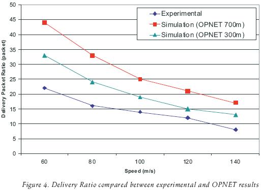
Our results are slightly different from the OPNET network simulator because our omni–directional antennas were mounted inside the cars instead of on their respective roofs. The pigtail cable used in the experiment was too small to extend it more than 1m. Similar results are reported in (Michel, 1998), who investigated the effect antenna position had on the packet delivery ratio and degradation. They found that antennas mounted on rooftops provide better reception than those mounted on dashboards.
Conclusions
In this work, we have shown that IEEE 802.11b wireless networks are suitable for inter–vehicular communication and confirm our hypothesis with the results of two propagation models.
According to large scale models, the maximum distance between the transmitter and the receiver is 446 m; however the System Operating Margin (SOM) feasible at 446 m is over 13 dB, which is above the minimum margin recommended. Nevertheless, we have found that the Doppler Effect does not alter the communication between the communication pairs at high speeds in small–scale models.
Finally, we realized an experiment to validate the analytical results represented in the worst case scenario, when the transmitter and receiver are traveling in opposing directions. Although not optimal, results show that a minimum of 8 packets can be delivered when the transmitter and receiver antennas are mounted on the dashboard.
Acknowledgements
Our tanks to the Dirección General de Asuntos del Personal Académico of UNAM for the Support and financing for the projects PAPIIT IN 104907 and PAPIME PE103807.
References
Abhayawardhana V.S., Wassell I.J., CrossbyD., Sellars M.P., Brown M.G. Comparison of Empirical Propagation Path Loss Models for Fixed Wireless Access Systems. IEEE, 61st. Vehicular Technology Conference, 2005,Vol. 1, pp. 73–77. [ Links ]
Brad Karp B., Kung H.T. GPSR: Greedy Perimeter Stateless Routing for Wireless Networks. Proceedings of the 6th Annual ACM/IEEE International Conference on Mobile Computing and Networking (MobiCom 2000), pp. 1–12. [ Links ]
D'Amico W.P., Lauss M.H. Wireless Local Area Networks Flight Demonstration for High Doppler Conditions. John Hopkins Apl Technical Digest, 25(4):335–342. 2004. [ Links ]
David A. Maltz D.A., Broch J., Johnson D.B. Lessons From a Full–Scale Multihop Wireless Ad–Hoc Network Testbed. IEEE Personal Communication, 8(1):8–15. 2001. [ Links ]
Jatinder Pal Singh J.P., Bambos N., Srinivasan B., Clawin D. Wireless LAN Performance under Varied Stress Condition in Vehicular Traffic Scenarios. IEEE Vehicular Technology Conference, fall 2002, Vol. 2, pp 743–747. [ Links ]
Howard H. Xia H.H., Bertoni H.L., Maciel L.R., Lindsay–Stewart A., Rowe R. Radio Propagation Characteristics for Line–of–Sight Microcellular and Personal Communications. IEEE Transactions on antennas and propagation, 41(10): 1439–1447. 1993. [ Links ]
Howard H. Xia H.H., Bertoni H.L., Maciel L.R., Lindsay–Stewart A., Rowe R. Microcellular Propagation Characteristics for Personal Communication in Urban and Suburban Environments. IEEE Transactions on Vehicular Technology, 43(3): 743–752. 1994. [ Links ]
Jinyang Li J., Jannotti J., De Couto D.S.J., Karger D.R., Morris R. A Scalable Location Service for Geographic Ad Hoc Routing. ACM Mobicom 2000. Boston, MA. 2000. [ Links ]
Michel L.B. DS/SS Inter–Vehicular Communication Experiments in 2.4 GHz ISM Band. IEEE International Conference on Intelligent Vehiculars. 1998. [ Links ]
L.B. Mosque M., Fussler H., Hartenstein H., Franz W. Performance Measurements of a Vehicular Ad Hoc Networks. 59th IEEE Vehicular Technology Conference, 2004, Vol. 4, pp. 2116–2120. [ Links ]
Mosque M., Fussler H., Hartenstein H., Franz W. Performance Measurements of a Vehicular Ad Hoc Networks. 59th IEEE Vehicular Technology Conference, 2004, Vol. 4, pp. 2116–2120. [ Links ]
Part II: Wireless LAN Medium Access Control (MAC) and Physical Layer (PHY) Specifications. Part 11. IEEE Std. 802.1 1b–1999. [ Links ]
Singh J.P., Bambos N., Srinivasan B., Clawin D., Yonchun Y. IEEE Wireless Communication Networking Conference, 2005, Vol. 3, pp. 1676–1682. [ Links ]
Stefano Basagni, Imrich–Chalamtac S.B., Syrotiuk V.R. A Distance Routing Effect Algorithm for Mobility (DREAM). MOBICOM 98. 1998. Pp. 76–64. [ Links ]
Theodore S. Rappaport T.S. Wireless Communications: Principles and Practice. Prentice Hall. Communications Engineering and Emerging Technologies Series. 2002. [ Links ]
Wang S.Y., Lin C.C., Hwang Y.W., Tao K.C., Chou C.L. A Practical Routing Protocol for Vehicle–Formed Mobile Ad Hoc Networks on the Road. IEEE Intelligent Transportation Systems. 2005. Pp. 161–166. [ Links ]
About the authors
Raúl Aquino–Santos. Graduated from the University of Colima with a BE in Electrical Engineering, received his MS degree in Telecommunications from the Centre for Scientific Research and Higher Education in Ensenada, Mexico in 1990. He holds a PhD from the Department of Electrical and Electronic Engineering of the University of Sheffield, England. Since 2005, he has been with the College of Telematics, at the University of Colima, where he is currently a research professor in telecommunications networks. His current research interests include wireless and sensor networks.
Victor Rangel–Licea. Received the B. Eng (Hons.) degree in Computer Engineering in the School of Engineering from the "Universidad Nacional Autónoma de México (UNAM)", Mexico in 1996 and the M.Sc. in Telematics from the University of Sheffield, U.K. in 1998. He holds a Ph.D. from the Centre for Mobile Communication Research, EEE Department, at the University of Sheffield, U.K. Since 2002, he has been with the School of Engineering, UNAM, where he is currently a Research–Professor in telecommunications networks. His research focuses on fixed, mesh and mobile broadband wireless access networks, QoS over IP, traffic shaping, scheduling, handoff procedures and performance optimization for IEEE 802.16 (WiMAX) based networks.
Luis A. Villaseñor–González. Received an engineering degree in electronics from UABC, Mexico (1993); M.Sc. in electronics and telecommunications from CICESE, Mexico (1997); and PhD in electrical engineering from the University of Ottawa in 2002. He is currently a research professor at the CICESE research center. He collaborated as a network research engineer at the Communications Research Centre in Ottawa, Canada. At CRC he was involved in a variety of research activities in network technologies for the Government of Canada between 1999 and 2003. His current research interests include Mobile Ad–hoc Networks, wireless communications networks, QoS protocol architectures, performance analysis and evaluation of Internet technologies and computer networks. He is currently a member of the IEEE.
Arthur Edwards. Received his masters degree in Education from the University of Houston in 1985. He has been a research professor at the University of Colima since 1985, where he has served in various capacities. He has been with the School of Telematics since 1998. His primary areas of research are Computer Assisted Language Learning (CALL), distance learning, collaborative learning, multimodal leaning and mobile learning. The primary focus of his research is presently in the area of mobile collaborative learning.

