


Serviços Personalizados
Journal
Artigo
 Inglês (pdf)
 Artigo em XML
 Referências do artigo
 Enviar este artigo por email
Indicadores
-
 Citado por SciELO
 -
 Acessos
Links relacionados
-
 Similares em
SciELO
Similares em
SciELO
Compartilhar

 Permalink
Ingeniería, investigación y tecnología
versão On-line ISSN 2594-0732versão impressa ISSN 1405-7743
Ing. invest. y tecnol. vol.10 no.2 Ciudad de México Abr./Jun. 2009
Handoff Between a Wireless Local Area Network (WLAN) and a Wide Area Network (UMTS)
Traspaso entre una red inalámbrica de área local (WLAN) y una red de cobertura amplia (UMTS)
J. Sánchez–García1, Luis A. Villaseñor–González2, Mario E. Vaquera–Flores3 and Raúl Aquino–Santos4
1 Departamento de Electrónica y Telecomunicaciones, CICESE, México. E–mail: jasan@cicese.mx
2 Departamento de Electrónica y Telecomunicaciones, CICESE, México. E–mail: luisvi@cicese.mx
3 Departamento de Electrónica y Telecomunicaciones, CICESE, México. E–mail: vaquera@cicese.mx
4 Facultad de Telemática, Universidad de Colima, México. E–mail: aquinor@ucol.mx
Recibido: octubre de 2007
Aceptado: diciembre de 2007
Abstract
With the appearance of wireless data networks with variable coverage, band width and handoff strategies, in addition to the growing need of mobile nodes to freely roam among these networks, the support of an interoperable handoff strategy for hybrid wireless data networks is a requirement that needs to be addressed. The current trend in wireless data networks is to offer multimedia access to mobile users by employing the wireless local area network (WLAN) standard IEEE802.11 while the user is located indoors; on the other hand, 3rd generation wireless networks (WAN) are being deployed to provide coverage while the user is located outdoors. As a result, the mobile node will require a handoff mechanism to allow the user to roam between WLAN and WAN environments; up to this date several strategies have been proposed (Sattari et al., 2004 and HyoJin, 2007) in the literature, however, none of these have been standardized to date. To support this interoperability, the mobile node must be equipped with configurable wireless inetrfaces to support the handoff between the WLAN and the WAN networks. In this work a new algorithm is proposed to allow a mobile node to roam between a wireless local area network (IEEE802.11) and a WAN base station (UMTS), while employing IP mobility support. The algorithm is implemented in simulation, using the Network Simulator 2.
Keywords: Handoff, WLAN, UMTS, Mobile IP (MIP).
Resumen
Hoy en día existe una gran variedad de redes inalámbricas de datos que proporcionan coberturas variables, diferentes anchos de banda que implementan diferentes estrategias de traspaso; adicionalmente se presenta una gran demanda por parte de los usuarios móviles por utilizar libremente la cobertura que proporcionan este tipo de redes. Por lo anterior, existe una necesidad de la implementación de mecanismos de traspaso que permitan la interoperabilidad en los traspasos que se presentan en redes inalámbricas híbridas. La tendencia actual, es la de proporcionar acceso para aplicaciones multimedia utilizando redes inalámbricas de área local (WLAN), utilizando el estándar IEEE 802. 11 para interiores; por otro lado, se están instalando redes inalámbricas de y generación para proporcionar cobertura en exteriores. Como resultado, los nodos móviles requieren un mecanismo de traspaso para permitir la comunicación en ambientes WLAN y WAN; a la fecha, se han propuesto diversas estrategias en la literatura (Sattari et al., 2004 y Hyo Jin, 2007); sin embargo, ninguna de éstas ha sido estandarizada. Para habilitar la interoperabilidad, el nodo móvil debe ser auto–configurable para permitir la movilidad entre las redes WLAN y WAN. En este trabajo se propone un algoritmo para permitir el traspaso de un nodo móvil dentro de una red inalámbrica de área local (IEEE 802.11) y una estación base WAN (UMTS), utilizando el soporte de movilidad IP. El algoritmo se implementó en simulación utilizando la herramienta Network Simulator 2.
Descriptores: Traspaso, redes inalámbricas de área local (WLAN), UMTS, IP Móvil (MIP).
I. Introduction
With the large deployment of WLAN accesss points (APs) in public places, high speed wireless data services are be coming increasingly popular, but they are not available everywhere. Similarly, cellular companies are mi grating from second generation (2G) to 2.5 or 3G technologies, thus al lowing them to offer higher data rate wide area network (WAN) connections that enable faster data transfers. Future wireless multimedia terminals will be able to connect to both WLANs and WANs, and switch between them with out interrupting on going communication sessions.
It is highly advantageous to make use of WLAN networks, when ever they are available, and be able to switch to a wide area cellular network when the WLAN is no longer available. This is because WLANs (like IEEE 802.11) offer high data rates at the expense of a reduced coverage area (generally free), while WANs –like the General Packet Radio Service (GPRS) or Universal Mobile Telecommunications System (UMTS)– offer great geographic coverage, but with reduced data rates.
The handoff (HO) procedure is the mechanism by which a data connection in progress between a mobile terminal and a corresponding terminal is transferred from an accesss point (AP) to another one, or to a cellular network base station (BS). The HO from a WLAN AP to a UMTS base station should be made with very low priority, while the HO from a UMTS BS to an AP should be made when ever a WLAN is available, as a result of the increased band width availability in WLANs (Pahlavan, et al., 2000); in addition, the utilization cost parameter must be considered too, as cellular operators charge an additional fee to provide data services to their customers.
There are two HOs types (Stemm et al., 1998): the horizontal HO that is defined like a HO between BSs (or APs) that are using the same wireless network technology, and the vertical HO which takes place between base stations that are using different wireless networking technologies; this work considers the vertical HO strategy, as well as, horizontal HOs between WLANs.
The vertical HO is divided in two categories: an ascendant vertical HO defined as a HO from a WLAN towards a wireless network with larger cell size whose coverage includes the WLAN, and a descendant vertical HO defined as a HO towards a wireless network with smaller cell size. To illustrate this procedure, figure 1 shows a person walking with a mobile terminal while connected to the Internet. As the terminal moves inside the hybrid network, several HOs must take place: starting at point a), the terminal passes from UMTS to a WLAN, this corresponds to a descendant vertical HO; point b) indicates the HO between two WLANs, called horizontal HO; point c) illustrates an ascendant vertical HO.

A HO is triggered based on the availability of a network and the priority policy used to select a network. One of the parameters used to decide that a HO must take place corresponds to the Received Signal Strength Intensity (RSSI), but this is not enough to give priority to a network during the HO procedure; parameters like utilization cost and available band width must also be considered. There are other methods that can be used to make the HO decision, like the one de scribed in (Matusz et al., 2003), where a HO decision is based on the through put and a time hysteresis (in the order of seconds) is considered to avoid the ping–pong effect1; however, the time they consider to wait for a handoff is relatively high and they do not specify the radio channel environment employed in their simulations.
In this work a metric is used to trigger the HO procedure; this metric is based on four parameters from each network: cost, bandwidth, distance and RSSI (each of these parameters is assigned a different weight). The vertical and horizontal HO mechanism is evaluated, while verifying that packet loss is minimized and the connection is maintained during the HO process.
The remainder of this paper is organized as follows. A review of recently proposed handoff procedures is presented in Section II. Section III describes possible ways to interconnect UMTS and WLAN. The mobility support in IPv4 is presented in Section IV. The proposed HO algorithm, inherent problems and the employed metrics are described in Section V. Section VI presents a description of the simulation model and the simulation scenarios employed. The simulation results are presented in Section VII. Finally, the conclusions of this work are presented in section VIII.
II. Related work
Sattari et al. (2004) propose anetwork architecture for a seam less hand over between WLAN and UMTS, based on two already existing mobility protocols, Session Initiation Protocol (SIP) and Mobile IP. They define a Hand over Entity, which is a set of functions located within the UMTS network, as the responsible for Handover Management. They propose three solutions: Mobile IP based, SIP based and a Hybrid based solution. Although they analyze the problems posed by each solution, they do not provide any simulation results.
Liu and Zhou (2005) propose an internetworking architecture between WLAN and UMTS, based on IPv6, Mobile IP and the 802.16 air interface (called Hybrid Coupling with Radio Access System). They propose two processes, one for vertical down ward Handoff (a mobile node starts in a UMTS network and goes to a WLAN) and another for vertical up ward Handoff. They compare their architecture with both a tight coupling and a loose coupling, showing that their proposal has a better performance (in terms of transmission and processing cost).
Sasikala et al (2006) propose a Handoff technique from WLAN to UMTS, based on the loose coupling integration (independent architecture), aiming at the reduction of delay and packet loss when the mobile moves from a WLAN boundary to a UMT S network. The decision algorithm is based on the received signal strength, where the stations have to detect a weak received signal or failed frame transmission. They assume a hot spot WLAN is served by various accesss Points (APs), where the boundary APs transmit a bit indicating that it is possible to exit the hot spot coverage. Their simulation results show a reduction in latency for the optimized algorithm, compared with the seamless technique.
Kim and Song (2007) propose a vertical Handoff scheme that uses Mobile IP, aiming at the reduction of the packet loss due to the ping pong effect. They assume that the WLAN is located a s a hot spot inside the UMTS coverage area. The protocol is based on the received signal strength of both the WLAN AP and the UMTS base station; before making the Handoff decision, it verifies if the user is a pedestrian or if it is traveling on a motorized vehicle. To decrease the ping pong effect, the signal strength thresholds can be adjusted dynamically.
The proposal presented in this work differs from the previous approaches in the way the threshold variable (metric) is calculated; the proposed algorithm takes into account four parameters:
– Cost of the service
– available bandwidth
– Distance to the AP (or BS)
– signal strength
III. Interconnecting a WLAN and an UMTS Network
The transmit power is one of the main parameters that are world wide regulated, and the transmitter power varies among different regions. Many of the IEEE 802.11 wireless manufacturers have selected 100 mW as the transmit power level by default. In Europe 100 mW is the highest power level, while in North America the highest power level is 1000 mW (O'Hara et al., 1999). The transmit power values used in base stations (BS node in UMTS), range from 30 dBm to 21 dBm according to the 3GPP Recommendation (3GPP TR 25. 942 V3. 1.0, 1999).
UMTS is a third generation wireless system (3G) developed in Europe and contemplated in IMT–2000 (International Mobile Telecommunications 2000), this is a 3G standard that includes several technologies, from which the dominants in the market are UMTS and cdma2000 (developed in the USA).
This work is based on UMTS TDD, as this was the model available in the simulation tool NS–2. One of the advantages of TDD is the fact that the transmission rates can be dynamically adjusted in the uplink and downlink, some thing that can not be done in FDD mode because the links are symmetric. If the TDD downlink needs more slots and the uplink has available slots, the available slots may be transferred from the uplink to the downlink.
a) UMTS network architecture
GPRS is the packet core network of UMTS. It includes two network nodes: the Serving GPRS Support Node (SGSN) and the Gateway GPRS Support Node (GGSN). The SGSN monitors the user location and provides security and accesss control functions. The GGSN provides routing information of the connected users to the Packet Switched (PS) network and it provides interconnection with external PS networks.
The telecommunications technology trend is towards an IP world, for this purpose the 3GPP release 5 proposes anarchitecture as shown in figure 2. The foreign agent (FA) (or home agent, HA) functionality will be placed inside of the GGSN; the GGSN will send Agent Advertisements when it receives a Packet Data Protocol (PDP) request from a mobile equipment. An other proposal is that the SGSN and GGSN can be combined in a node called Internet GPRS Support Node (IGSN); the IGSN will act like a FA and will provide a tunnel to transfer packets from, and to, the user HA (3GPP TR 25.923 V3.0.0, 2000).

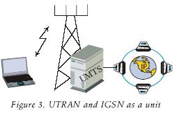
As can be appreciated from the 3GPP recommendations, the basis for the next generation network with IP convergence have been established; the 3GPP release 6 specifies the general procedures for the particular case of the HO between WLAN and UMTS. In the present work, the IGSN and Universal Terrestrial Radio Accesss (UTRA) were considered as a unique entity (figure 3).
b) UMTS and WLAN interconnection points
One of the main objectives in the WLAN and UMTS interconnection is to avoid, as much as possible, changes at the physical and link layers. This will insure that the current networks will keep working, with out requiring the user to make changes at these lower layers; the approach proposed in this work is based on modifications at the network and upper layers.
There are two configuration scenarios for the interconnection of UMTS and WLANs; the first case is when the cellular operator is the administrator and owner of the WLAN, the second case is when the wireless Internet Service Provider (WISP) is the owner. In the first scenario, the cellular operator has billing and authentication mechanisms that allow him the management and total control of the WLAN. In the case where the WLAN is operated by WISP, both operators will have their own billing and authentication mechanism (Salkintzis et al., 2002).
Figure 4 shows the five possible options for the interconnection points between a UMTS and a WLAN (Prasad et al., 2003). The interconnections (1) and (2) will al ways have interaction between the AP (via the Interworking Unit, IWU) and the UMTS Core network (CN of PS UMTS); the interconnection is possible trough the SGSN and GGSN respectively.

In the first interconnection point (known as tight coupling) the WLAN is connected as a UMTS cell, like any other Radio Accesss network (RAN), through the Iu interface; where the Interworking Unit (IWU) is a Radio Network Controller (RNC) emulator between the WLAN and SGSN. In the second interconnection point (known as loose coupling) the WLAN is connected as a routing area through the Gi interface; where the IWU is based in a SGSN emulator between the WLAN and GGSN. In both cases (1 and 2, in figure 4), UMTS will be the master network and WLAN the slave network, this means that UMTS manages the mobility and security issues (Prasad et al., 2003). All the traffic will first reach the SGSN, or GGSN, before it arrives to its destination, even though the final destination is inside the WLAN, this is an inconvenient, because it may become a bottle neck in the UMTS network.
In the third interconnection method, the architecture is based in the Virtual Accesss Point (VAP) which reverses the function played by the components in the last two cases. Here, the WLAN is the master network and the UMTS is the slave. The mobility is managed according to the WLAN and the recent draft Interaccess Point Protocol (IAPP) which has been specified to standardize the communication between APs over the wired interface (Pahlavan et al., 2000), but the architecture is not scalable because the VAP must al ways be associated with the Extended Service Set (ESS) of the WLAN. The transit technology (when roaming) that the WLAN sees is between different APs in the ESS and the VAP is considered as another WLAN AP. From the WLAN point of view, UMTS appears as a BSS or picocell associated with another AP (VAP, in this case). In the UMTS air interface, every packet will have double UDP/TCP and IP/PPP headers. More over, there will be a MAC 802.11 header in all the headers related with UMTS. This interconnection is considered inefficient, due to the excessive use of headers and it is not clear how will the VAP operate with the 802.11 AP (Prasad et al., 2003).
The fourth interconnection method introduces a mobility gateway (MG) between the UMTS and WLAN networks. The MG is a proxy implemented in the UMTS or WLAN side. Its purpose is to manage the mobility and routing problems. But the real reduction of packet headers (overhead) by employing this architecture is not significant, due to the need for proprietary control protocols in addition to transit between different technologies.
Another proxy in convenience is the poor performance due to increased latency in the client server communication trajectory and the fact that it is not easy to know the number of proxies needed to achieve an optimum performance.
The fifth interconnection method is based on mobile IP to handle the mobility management problems (known as no coupling). Here, UMTS and WLAN are peer to peer networks and the same problems exist as in the previous interconnection method (4); furthermore, the reference point that makes it possible to connect UMTS, via the GGSN, to the IP network operator or Internet is also the Gi interface (Salkintzis et al., 2002). Since IP is in the core of actual and future wideband networks, this work employs this type of interconnection method (i.e. number 5).
IV. Mobility support in IPv4
The mobility sup port at the network layer has the advantage of being independent from the link layer. Mobile IP 2 implements the required functionality to pre vent the disconnection of ongoing communication sessions during the handoff procedure of a mobile node (MN); the mobile node is al ways identified by its home address, in dependently of its current point of attachment to the Internet. While the mobile node is out side of its home IP sub–network, it can be associated to a care–of–address (COA); the COA indicates the current MN's localization. The following subsections explain with more detail the components and functionality of Mobile IPv4.
a) Mobile IPv4 Terminology
This section presents a description of the terminology employed in Mobile IPv4 (MIP)3.
– Correspondent Node (CN). A node that communicates with a mobile node (MN). It can be mobile or stationary.
– Encapsulate. Consist in adding a header to the original IP packet (i.e. packets are encapsulated).
– Tunnel. A delivery path between two nodes where the packets payload are original packets.
– Home Address. An IP address that is assigned for an extended period of time to a MN.
– Care–of–address (COA). An address associated with a MN while it visits a foreign link.
– Home Agent (HA). A router of the MN where it has registered its current COA.
– Foreign Agent (FA). A router at the mobile node's visited network.
b) Mobile IP Functionality
The different tasks executed by the mobile nodes during the HO process are illustrated in figure 5.

– The mobile agents advertise its presence via Agent Advertisement messages. An impatient MN may optionally solicit an Agent Advertisement message.
– A MN receives the Agent Advertisements and determines whether it is located at its home network or at a foreign network.
– Packets addressed to the mobile node arrive to the home network via standard IP routing (step 1).
– When a MN moves away from its home network, it gets a COA at the foreign network, either by request or by listening to an Agent Advertisement; by contacting a Dynamic Host Configuration Protocol (DHCP); or by means of a Peer to Peer Protocol (PPP). While the MN is away from the home network, the MN registers every new COA withits HA.
– While the MN is at a foreign network, the packets are intercepted by the HA, encapsulated and tunneled to the MN using the COA (step 2).
– The encapsulated packets arrive to the FA, the external IP header is re moved and the original packets are for warded to the MN (step 3).
– The data packets generated by the MN are routed by means of standard IP routing; this is the model employed in this work.
– In the reverse direction, packets sent by the MN are generally delivered to its destination, not necessarily passing through the home agent (step 4). This is known as triangulation.
c) MIP message flow during a HO procedure
The sequence of messages interchanged between the MN and the HA (via the Foreign Agent) are shown in figure 6.

d) Route optimization
To avoid the triangulation, it is possible to employ a route optimization mechanism; the idea is that the correspondent node (CN) will be able to directly send encapsulated packets to the mobile node by employing the MN's COA; this is achieved by means of a binding update message sent by the MN to the CN. The route optimization approach requires changes in the protocol stack of the CN. The route optimization mechanism is not employed in the actual MIP model used in this work.
e) Mobility detection at layer 3
The mobility agent (e.g. the HA or FA) periodically broadcasts Agent Advertisement messages, consequently the MN has the opportunity to verify if it is located at its home network or if it has moved to a foreign network. The HO mechanism is triggered by this type of message.
When the MN detects that it has moved to a different network (i.e. a foreign network) it gets a new COA by using the information provided in the Agent Advertisement messages sent by the mobile agents (e.g. the FA); once the MN has acquired a COA, it proceeds to register the new COA with the HA. It should be noted that several data packets may be lost during the HO procedure, as the MN gets temporally disconnected during the period when the Agent Advertisement messages stop being received, to the time when the MN gets connected to an other router; it is also possible that the MN receives messages from several agents and may get connected to the less appropriate. As a result, the MN can improve the HO procedure by employing additional information whenever this may be available at the MN, for example, by using the information provided from the physical layer (Perkins et al., 1996; 2003).
This work considers that the MN has an Application Programmable Interface (API) to know its position and determine the distance to its current agent (by means of a Global Positioning System, GPS), and also to sense the power associated with the packets received from the advertising agents. It is also considered that the MN can receive packets from different base station with the same interface. Further more, it is assumed that Agent Advertisement messages provide the cost information, number of users and network type.
Each time a MN receives a mobility Agent Advertisement message, it verifies if the agent is already included in the List of known mobility agents, if it is not, it is added to the List. Then, the parameters (i.e. RSSI, Distance, network Type, network cost, network users) are updated and stored. The consideration of these parameters (except Distance) in the decision for calculating a metric and choosing the preferred agent is one of the main contributions of this work. The Agent Advertisement messages are generated every second by the agents, and when ever the agents receive an Agent Request message. When the MN detects that it returns to its home network (by receiving an Agent Advertisement fromits HA), the MN informs to its HA that it must stop intercepting packets addressed to it; consequently data packets sent to the MN by a CN will get routed directly to the MN within the home network. From this point on, the MN uses its home address as the localization identifier instead of the COA. With the help of the MIP parameters described in this section, the MN can get a list of possible mobile agents to use, and with the aid of a HO algorithm determine which is more convenient to use. The next section ex plains some HO algorithms, including the HO algorithm proposed for this work.
V. Handoff algorithm
a) Handoff procedure between WLAN and UMTS
The Handoff (HO) procedure employed by a MN to switch between WLAN and UMTS networks is illustrated in figure 7 (Prasad et al., 2003).
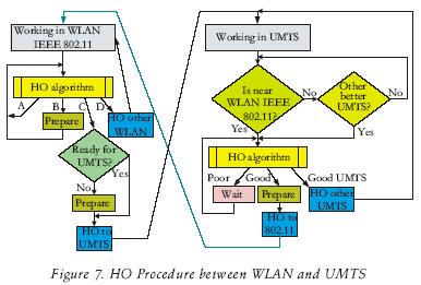
There are four possible actions that may be taken by the MN as a result of the HO algorithm: While operating in the WLAN, the HO algorithm will select option A given that it receives a good signal strength from its current associated AP; option B indicates that the MN is beginning to receive a poor signal strength from the AP and should prepare to start a HO; option C is selected when a handoff to the UMTS network is required and there is not an other WLAN AP to be selected; option D is selected to trigger a HO procedure to select a new WLAN AP.
The following scenario depicts a MN moving away from WLAN coverage and moving into UMTS coverage:
1) Initially, the MN receives a strong signal from the AP, and the MN is connected to the WLAN network.
2) As the MN moves away from the AP, the received signal strength be comes weaker. The MN is continually analyzing the received signals, looking for a better AP or BS. The HO algorithm uses the available information to make a decision: to change, or not, to the UMTS network. The connection procedure is started to activate the UMTS wireless interface card.
3) The HO algorithm in the MN decides to disassociate from the WLAN and associate with the UMTS network.
4) The MN gets in touch with the foreign agent (FA) and obtains a COA.
5) The HA in the WLAN is informed about the new COA and begins the interception of datagrams ad dressed to the MN, it encapsulates them and sends them to his FA. The FA then deencapsulates the datagrams and de livers them to the MN.
6) If the MN moves into the WLAN coverage, it begins a reverse HO.
b) Handoff and the Ping–Pong effect
Handoff is the mechanism by which a data connection in progress between a mobile terminal and a corresponding terminal is transferred from a connection point to another: for example, as the MN moves away from a base station, the signal level gets weak and a handoff procedure must be executed to switch to another base station. The signal level degradation is a random process and a simple decision mechanism which is only based on the signal power measurement may result in the so called ping–pong effect (Pahlavan et al., 2000). The ping–pong effect refers to several consecutive backward and forward HOs; this happens when the signal power is varying around the threshold value used within the HO algorithm to decide when to make a HO. This is an inconvenient for the user, due to the switching cost and the induced delay in each handoff.
c) Problems during the Handoff
The decision mechanism or HO control can be located in a network entity (like a cellular base station) or at the mobile node; these scenarios are called HO controlled by network and HO controlled by mobile, respectively. In GPRS, the information sent by the MN can be employed by the network entity to make the HO decision; this is called HO assisted by the mobile. In this work, the decision mechanism for HO is implemented at the MN.
This work employs the signal power, distance, network cost and available band width parameters; further more, it uses a retain time counter and a hysteresis margin (Hm), which is not defined as a received signal power mar gin, but as a metric margin resulting from all the previous parameters. It also uses a metric threshold (Um).
d) Handoff algorithm
Almost all known algorithms are based in the received signal power (Pollini, 1996) and were designed for HO between the same types of networks (mostly for cellular networks). Other techniques have recently been proposed, like pattern recognition based on neuronal networks or diffuse logic systems, however these algorithms increase the computational cost in the mobile node; in addition, these techniques still employ the RSSI parameter.
This work follows a priority strategy for the HO between WLAN and UMTS, and different priorities, cost values and numbers of mobile nodes were pre–established during simulation4. The algorithm implemented in this model considers that UMTS and WLAN have different transmission signal strength levels, then it does not make sense to use only the RSSI parameter to decide among them (UMTS BSs generally transmit with a higher power strength than WLAN APs). If only this parameter is used, the MN will always be connected to UMTS, even if the MN was inside the WLAN coverage area. The use of a single R SSI parameter is appropriate for horizontal HO.
In the proposed HO algorithm, a new BS or AP will be chosen (called new agent, NA) if and only if the following two conditions are met:
– during a predetermined retention time (Dwell–timer) the new agent metric (metric_NA) minus an hysteresis margin is greater than the metric of the actual or older agent (metric_VA) (Eq. 2) and,
– the actual agent metric (metric_VA) is smaller than a predefined threshold (Um) value.
The agent metrics are calculated by taking into account several parameters, according to the following equation:
metric=wight_Cost (1—Cost)
+ weight_BandWidth (BW_user)
+ weight _Distance(1–Distance)
+ weight _RSSI(RSII) (1)
A new agent (NA) is chosen if at the end of Dwell–timer the following inequality holds true:
metric NA–Hm>metric VA<Um (2)
Um5 is a threshold which is used to determine if the metric_VA is poor.
In equation, the variables de noted with the prefix "weight" have a value between 0 and 1, and added are equal to one. Cost is a value that represents the network charge (from 0 to 1). BW_user is the band width that corresponds to the MN, which is calculated by dividing the total band width used in the network by the number of MNs in that network. The variable Distance is the normalized distance that exists between the MN and the BS or AP. Finally the RSSI variable is the strength indicator from the received signal. To avoid choosing an agent which is received with very low power, a RSSI _Threshold is defined, such that the agent metric (i.e. metric_NA or metric_VA) is set to zero when its strength is below the threshold:
if RSSI<RSSI Threshold then metric=0 (3)
During a HO procedure the MN follows the next sequence of steps:
1) The MN Link–Timer is restarted every 0.5 seconds.
2) The HO–trigger function verifies if Dwell–Timer is less or equal to zero. If so, Monitor–timer is reset and returns a HO–Trigger Authorization. Otherwise, the function returns a HO–Trigger Deny.
3) If the MN is not associated to any network and the HO–Trigger is authorized, the MN sends a HO–Request to both, UMTS and WLAN networks.
4) The base station receives the Agent Request and answers with an Agent Advertisement.
5) If the third step condition is not ful filled, the Link–Timer is re started.
VI. Implementation of the simulation model
The UMTS TDD extension for the network Simulator (NS–2) was developed at the University of Roma (Vacirca et al., 2003) using the ns–2.1b9a distribution, which had to be ported to the ns–2.1b7a version of NS–2, as we had an available work in progress from several universities regarding the HO between UMTS and WLAN from which we started our work. The implementation of the simulation model was done as part of a thesis developed at CICESE (Vaquera, 2004).
The UMTS–TDD extension manual for NS–2 (Todini et al., 2003) (preliminary version), provides a description and enough instructions to understand its implementation and how to develop simulations.
a) Autoconfigurable mobile node
To simulate a mobile node, a terminal model with a common layer 3 and two different lower layers (one for UMTS and an other for 802.11) was considered. The module that performs the interface between the common layer 3 protocol and the two different lower protocol stacks (MAC and PHY sublayers) is called RAMON (Reconfigurable Access Module for Mobile Computing Applications).
RAMON is a project developed at several Italian universities, among them the Palermo University; it consists of several interfaces added to the original ns–2 MN model, as can be seen in figure 8. The primitives sent between layer 3 and layers 2 are handled transparently by means of adaptation layers related to UMTS and 802.11, respectively. The RAMON node model makes use of two submodules: the Radio Resources control (RRC) and the Mobility Management (MM), as illustrated in figure 8. To calculate the attenuation of the radio signal, the model employs the Friss free space propagation model (1/r2 where r is the distance) for short distances and an approximation to Two Ray Ground (1/r4) in long distances. The approximation as sumes that flat earth reflection occurs.
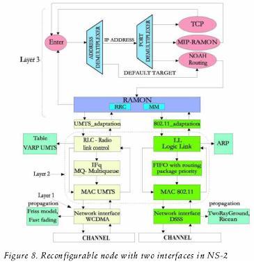
The routing protocol employed for this infrastructure network is NOAH (no Ad–Hoc) (Widmer, 2004). The cost and number of users can be established for every network; the band width of every network is divided between the number of users of that specific network. The node is autoconfigurable and before simulation the user can define several parameters like weight_Cost, weight _Distance, weight_BandWidth, weight_RSSI, the number of verifications (num_checks) before executing a HO procedure to avoid the ping–pong ef fect, and the RSSI_Threshold that will be used to trigger the HOs. The RSSI and RSSI _Threshold parameters were included into the RAMON model and are part of the contributions of this work.
b) Network scenario employed for HO
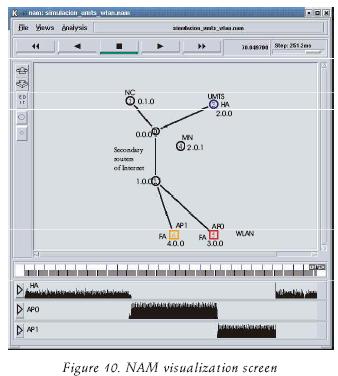
The simulation scenario considers a topology composed by one UMTS and two WLAN networks; the home agent (HA) is located at the UMTS network BS (the NS–2 UMTS module only supports the home network to be located at the UMTS network) and the foreign agents are the routers from the WLANs, as it is illustrated in figure 9. The simulation begins with the MN connected to the UMTS network and moving to a WLAN network with a constant speed of 3 km/h (0.8333 m/s). The simulation time is 70 sec. and at t = 0.1 sec. the MN (node 4 in the animator of NS–2, figure 10) begins to move towards the first WLAN accesss point (AP0 or node 5). The following paragraphs describe the movements made by the MN, which are illustrated in figure 9:

– The MN performs a descendant vertical HO crossing from UMTS to WLAN.
– At t = 30.0, the MN changes its direction and moves towards the other WLAN (AP1), thus executing a horizontal HO. The second WLAN is denoted by node 6 in figure 10.
– At t = 50.0, the MN changes again direction towards the UMTS to perform an ascendant vertical HO passing from WLAN to UMTS. The UMTS BS is represented by node 3 in.
During simulation, the MN opens a TCP connection by means of an FTP application; packets are sent from the FTP server (i.e. the correspondent node denoted as node 1 in figure 10) towards the MN. Data transfer begins at t = 0.2 sec. There are two intermediate nodes representing the Internet cloud, as illustrated in figure 10; these two routers are de noted with the node numbers 0 and 2. All the nodes have an associated hierarchical address.
The Agent Advertisement messages are broadcasted every second, and there set time of the monitoring, link and connection timers is 0.5 sec.
VII. Results and numeric analysis
The measured parameters in the simulation were: point to point delay, number of packets lost and HO delay. In addition, this section presents a comparative analysis between the results obtained for vertical (ascending and descending) and horizontal HOs.
a) Simulation parameters
Figure 10 illustrates the Network Animator (NAM) visualization of the network topology implemented for simulation in NS–2. The lower section of figure 10 shows the generated traffic between the agents and the mobile node (MN).
Table 1 shows the parameters employed for simulations; these values were obtained from (Vaquera, 2004) and represent a typical example, where the most important parameter is considered to be the associated network cost defined by the weight_Cost parameter.

b) Performance results
In this section we present the performance results for the point to point delay and the HOs delay. during normal operation conditions there were no packets lost6 in any of the simulated HO scenarios, except when the operation was under abnormal conditions; for example a person running at a speed of 20 m/s (72 km/h), and carrying his mobile terminal. Performance results for this last scenario are not presented in this work.
1. Handoff from UMTS to WLAN
The HO delay can be visualized in table 2; the delay to complete the HO is measured from the time the HO is triggered, until the time the MN finds it self connected to the new network.

Figure 11 shows the results obtained for the delay of the packets from the CN to MN (end to end); this figure illustrates the delay before and after the HO is made between UMTS and the first WLAN. It is observed that the delay is larger when the MN is connected to the UMTS, than when it is connected to the WLAN.

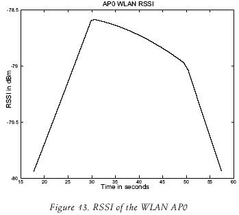
The received signal strength from the UMTS BS and the WLAN AP0 are shown in figure 12 and figure 13, respectively. Figure 14 shows the results of the RSSI that the MN measures from the UMTS BS; this information is presented as a function of the distance between the BS and the MN. An overlap is observed in (i.e. between distances 64 and 70 meters), this is due to the fact that the MN reaches a maximum distance at around 69 mts. and then it begins to come back closer to the UMTS BS.


2. Handoff between WLANs
The end to end delay of data packets sent from the CN to MN is shown in figure 15; the delay measurements are taken between t1 = 43.0 and t2 = 49.0 to include the horizontal HO procedure between AP0 and AP1. Table 3 shows the HO delay measured from the time the HO is triggered to the time when the MN is connected to the new network.


Figure 16 shows the graph of the RSSI measured by the MN from the WLAN AP1, during simulation.

3. Handoff from WLAN to UMTS
The packet end to end delay (i.e. CN to MN) is shown in figure 17; these results were obtained some seconds before and after the HO from the second AP WLAN to UMTS. Table 4 shows the HO delay measured from the time the HO is triggered to the time when the MN is connected to the UMTS again.


4. Comparison between HOs
This section presents a comparison and analysis of the HO results derived by simulation; performance results are evaluated in terms of the point–to–point packet delay and HO delay.
Point–to–point packet delay
Figure 18 shows the delay of the packets (packet size was set to 1000 bytes) during the entire simulation.

The packets that went through the UMTS BS, when the MN was connected to that agent, are the most delayed. Since the WLANs effective bit rate is larger than that of UMTS, it was found in the simulations that the packets suffer less delay when transmitted through the WLAN APs.
HO delay
Table 5 shows the measured delays during the HOs. It can be observed that the HO delay is larger between WLANs, where it was expected to be smaller, but this delay is random and is due to the Dwell and Link timers employed. This can be con firmed by observing the delay between "HO Start" and the first "Sent MIPT_REG" in table 2, table 3 and table 4, which are equivalent to 0.048785, 0.164219 and 0.009106 sec. respectively. The use of timers can be considered as a problem that reduces the efficiency, but is necessary to avoid the "ping–pong" ef fect.

Table 6 shows the HO delay at the transport layer (TCP). It is observed that the MN can receive packets from two connections at the same time; this happens when the MN (during a HO) is be ginning to receive packets from the new agent while there are pending packets (from the old agent) still on the air or cable. The "Detach" operation de noted in table 2, table 3 and table 4, does not imply disabling the interface, and the MN can still receive packets from the previous BS or AP.

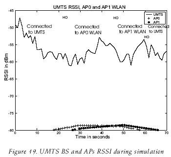
Figure 19 presents the graphics obtained for the measured RSSI at the MN from the UMTS BS, and from the accesss points located in both WLANs, during the entire simulation. The solid line represents the UMTS signal that MN receives and is present at all times, the cross and asterisk lines represent the signals of AP0 and AP1 respectively. It can be observed that the MN receives them with a RSSI greater than –80 dBm, good enough to connect with the network from which it receives the stronger signal. The vertical lines indicate the time at which the HOs are triggered.
VIII. Conclusions
Different alternatives for handoff between WLAN and UMTS were analyzed. In this work we implemented a HO algorithm while trying to reduce complexity and provide the best advantages (no coupling MIP based) of other previously re ported HO approaches. The vertical and horizontal HOs are performed with out losing any on going TCP connections and without losing packets.
A novel algorithm was proposed, implemented and evaluated to support horizontal and vertical handoffs between UMTS and WLAN networks; the HO algorithm relies on several metrics, including the RSSI. Previous works implement various algorithms, some of them even with high computational cost, as those that make use of neural networks, but still they rely on the RSSI metric.
It was concluded that the interconnection architecture between UMTS and WLAN by means of MIP represent a viable alternative to enable roaming between networks. The HO delay (with TCP) doesn't significantly affect the file transfer services, data and email, but it may affect real time applications, since it some times exceed the maximum allowed delay considered acceptable for voice and video applications (500 msec.). How ever, if the HOs do not occur frequently, the introduced HO delay may be considered not so annoying for voice or video applications.
The performance results in this work considered a TDD based UMTS network; however, recent extensions to the NS–2 UMTS model have implemented the FDD model, as a result, future work will consider the implementation of an FDD based UMTS network.
References
Gumming L., Chi Z. HCRAS: A Novel Hybrid Internet working Architecture Between WLAN and UMTS Cellular Networks (2nd, 2005) IEEE Consumer Communications and Networking Conference. 2005, 374–379 pp. [ Links ]
HyoJin K., JooSeok S. A Novel Vertical Handoff Scheme Based on Mobility Speed in Integrated WLAN and UMTS Networks. IEICE Transactions on Communications, E90–B (7):1844–1847. July 2007. [ Links ]
Matusz P., Machan P., Wozniak J. Analysis of Profitability of Inter–system Handovers between IEEE 802.11b and UMTS (28th Annual, 2003, Gdansk, Poland) Proceedings of the 28th Annual IEEE International Conference on Local Computer Networks (LCN'03). Gdansk, Poland, Oct 20th–24th, 210–217 pp. [ Links ]
O'Hara B., Petrick A. IEEE802.11 Handbook, a Designer's Companion. IEEE Press. First Issue. 1999. 173 p. [ Links ]
Pahlavan K., Krishnamurthy P., Hatami A., Ylianttila M., Makela J.P., Pichna R., Vallstron J. Handoff in Hybrid Mobile Data Networks. Personal Communications, IEEE, 7(2):34–47. 2000. [ Links ]
Prasad R., Muñoz L. WLANs and WPANs Towards 4G wireless. The Artech House. First Issue. Norwood. 2003. 276 p. [ Links ]
Perkins C.E. Mobile IP. IEEE Communications Magazine, 40(5):66–82. 2002. [ Links ]
Perkins C.E., Johnson D.B. Mobility Support in IPv6 (Annual, 1996, New York, USA) Proceedings of the Annual International Conference on Mobile Computing and Networking, MOBICOM. Rye, New York, USA. Nov. 10th 12th, 27–37 pp. 1996. [ Links ]
Perkins C.E., Johnson D.B.. Mobility Support in IPv6. draft–ietf–mobileip–ipv6–24.txt. 170 p. (on line) 2003. (Consulted on January 29, 2008). Available on: http://net.infocom.uniroma1.it/downloads/umts_ manual.pdf. [ Links ]
Vacirca F., Todini A. UMTS Module forns. (on line) 2003 (Consulted on January 29, 2008). INFOCOM Department, Rome University "La Sapienza", Rome, Italy. Inversion of ns–2.1b9a. Available on: http://net.infocom.uniroma1.it/reti_files/reti_downloads.htm. [ Links ]
Vaquera–Flores M.E. Handoff between IEEE802.11 wireless Local Area Network Access Points Environment and a Wide Area Network (WAN). Master of Science Dissertation. CICESE, Ensenada, Mexico. August 2004. 117 p. [ Links ]
Widmer L. Extensions to the ns Network Simulator (on line). 2004 (Consulted on January 29, 2008). Infrastructure Routing Type (no ad–hoc). March 1st 2004. Available on: http://icapeople.epfl.ch/widmer/MobileIP/ns–extension/ 3GPP TR 25.942 V3.1.0 1999. RF System Scenarios. Issue 1999, 111 p. [ Links ]
3GPP TR 23.923 V3.0.0 2000. Combined GSM and Mobile IP Mobility Handling in UMTS IP CN. Issue V3, 76 p. [ Links ]
1 Several unnecessary HOs are triggered when the threshold is crossed several times during a short time.
2 IP and IPv4 are used interchangeably throughout the document.
3 The terms, and most of the functionality of the procedures that are presented in this section, are consistent with the terminology employed in the early paper by Perkins (2002).
4 The WLAN AP can report how many users are currently connected to it, in order for the MN to roughly estimate the available band width; the same criteria can be used in the UMTS.
5 During simulations it was observed that Um delayed the HO without any benefit; then a value of 100 was used to speed up the HO procedure.
5 Packets transmitted from the BS, or the AP, to the MN.
About the authors
Jaime Sánchez–García. Received the engineering degree in electronics and communications from IPN–ESIME, Mexico (1976); a M.Sc. in electronics and telecommunications from CICESE Mexico (1979) and the D.Sc. in electrical engineering (major in communications) from The George Washington University (2001). Since 1979, he holds a research and faculty position at CICESE's electronics and telecommunications department. He won the 1st place in III Ericsson Yearly Award (1988) in México. His publications include several IEEE articles and international conferences. Current research interests include wireless and sensor networks, software radio, radio channel modeling and multicarrier CDMA. He is an IEEE and a IEICE member.
Luis A. Villaseñor–González. Received an engineering degree in electronics from UABC, Mexico (1993); M.Sc. in electronics and telecommunications from CICESE, Mexico (1997); and PhD in electrical engineering from the University of Ottawa in 2002. He is currently a research professor at the CICESE research center. He collabrated as a network research engineer at the Communications Research Centre in Ottawa, Canada. At CRC he was involved in a variety of research activities in network technologies for the Government of Canada between 1999 and 2003. His current research interests include Mobile Ad–hoc networks, wireless communications networks, QoS protocol architectures, performance analysis and evaluation of Internet technologies and computer networks. He is currently a member of the IEEE.
Mario E. Vaquera–Flores. Received a M.Sc. in electronics and telecommunications from CICESE, Mexico (2004).
Raúl Aquino–Santos. Received the electrical engineering degree from the University of Colima (1988); M.Sc. in electronics and telecommunications from CICESE, Mexico (1990); PhD degree from The University of Sheffield, England (2004). From 1990 to 1996 he was in charge of The Telecommunications and Networks Department of the University of Colima, and from 1996 to 2000 he was the director of the Faculty of Telematics. He has imparted several national and international courses and conferences related to information technologies, telecommunications, networks and multimedia. He has national and international publications, and has supervised several thesis and projects in under graduate and postgraduate programs since 1990.

