


 nueva página del texto (beta)
 Inglés (pdf)
 Artículo en XML
 Referencias del artículo
 Enviar artículo por email
 Citado por SciELO
  Similares en
SciELO
Similares en
SciELO 
 Permalink
1 Introduction
Accelerometers allow for measuring linear and rotational acceleration in one or more directions. Their applications are widely extended in various fields, from industrial and military systems to home products [–3].
Nowadays, the need to measure vibration has become especially important because it quickly brings information about the medium and uses where the device is working.
An area that uses optical mediums to detect vibration exists in accelerometers' development. Some of them, internally, have emitter-and-receiver-of-light devices, transforming optical signals into electrical ones [–6].
Other accelerometers use a waveguide to transmit a beam inside the accelerometer, measure the acceleration and drive the beam outside to transform it into an electrical signal.
Some advantages this type of device can offer are magnetic and electric field immunity, which can be used in hazardous environments and for long distances [–9].
Different measuring methods exist among accelerometers that use a waveguide; some use fiber optic with Bragg gratings [10, 11], interferometry [12], or optical power variation. In the last one, variants like the bending of fibers [–15] and the use of mirrors to redirect the beam [–18] exist.
In this paper, we present the test of an accelerometer that uses a mirror fixed over a membrane of flexible material that let the measurement in one direction (perpendicular to the plane of the membrane) and the effect of the used material and the applied geometry in the membrane over the measurement results.
2 Structure and the Principle of Functioning
The accelerometer structure consists of a PLA-material-housing where a reflective probe is fixed, inside housing a membrane with a ceramic mirror at the center. The accelerometer is a single-degree-of-freedom spring-mass system, with the membrane as the seismic mass (Fig. 1).
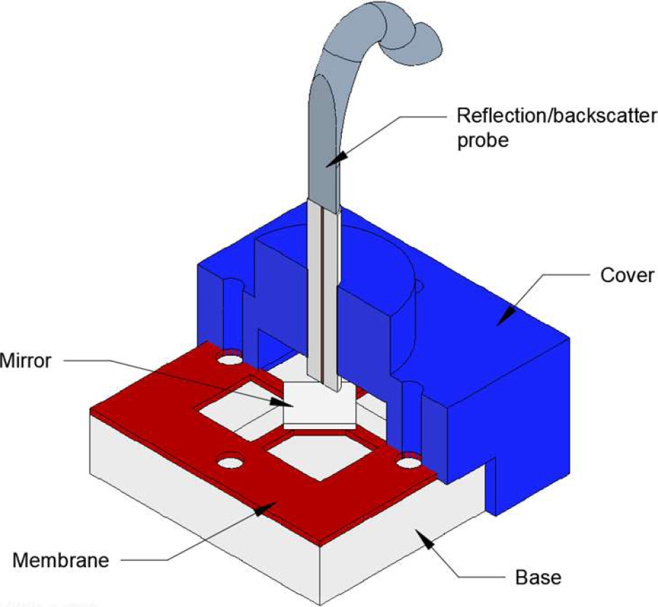
The membrane has been made of polyvinyl chloride (PVC), polyethylene terephthalate (PET), latex, and silicon and tested with different geometries to ensure either inclination or rotation of the central reflective about the axis parallel to the membrane plane is limited, so the mirror only moves in one direction.
Fig. 1 shows a section view of the accelerometer's structure, elements, and position. The reflective probe lets drive a laser light to its end in front of the mirror and receive the reflected light to guide it until a sensor light.
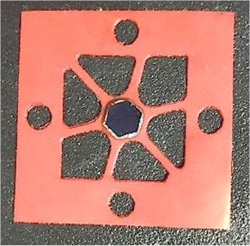
Fig. 2 shows the end of the reflective probe, where each circle represents a fiber optic end. The laser light is emitted to the mirror by the central point and caught back through one or more fiber optics around the central one.
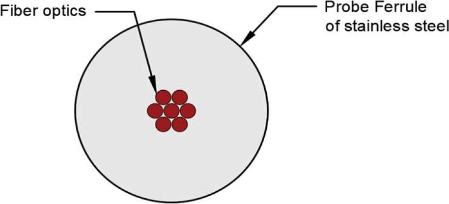
Fig. 2 End of the reflective probe. The central fiber optic drives light to one terminal of the probe, and the rest of the fiber optics (around the center) drive light to a second terminal
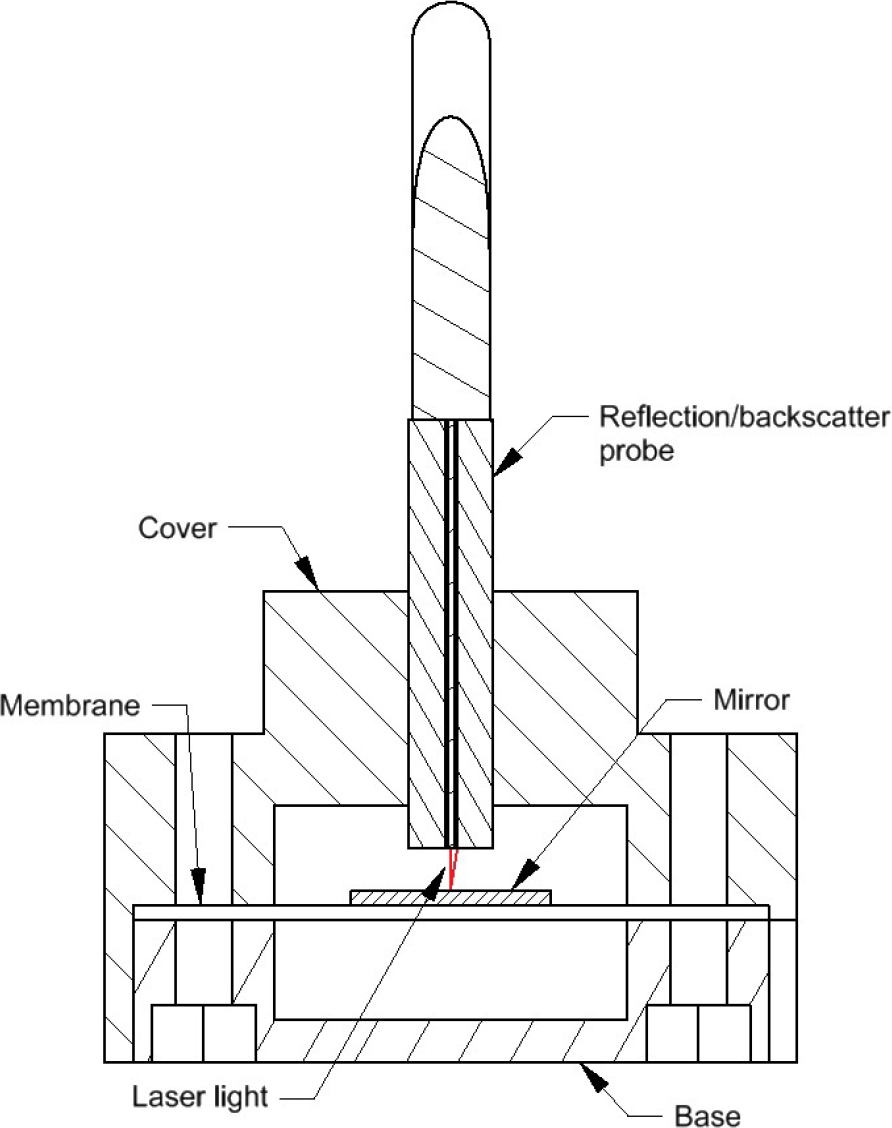
Fig. 3 shows a section view of the accelerometer that indicates how a laser beam travels from the central fiber to another fiber for conducting it to a light sensor.
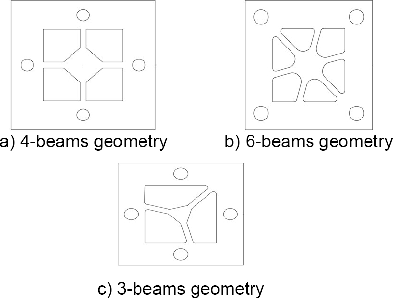
Three different geometries were made with a laser cutter to ensure the quality of the edges and were tested (Fig. 4 and 5). In addition, the researchers conducted a finite element analysis to verify the membranes' work conditions.
3 Material and Methods
Fig. 6 shows the main components of the experiment. The system comprises a laser diode U-LD-650543 of 650nm, a reflection/backscatter probe R400-7-VIS/NIR, and a TEMT600 Ambient Light Sensor.
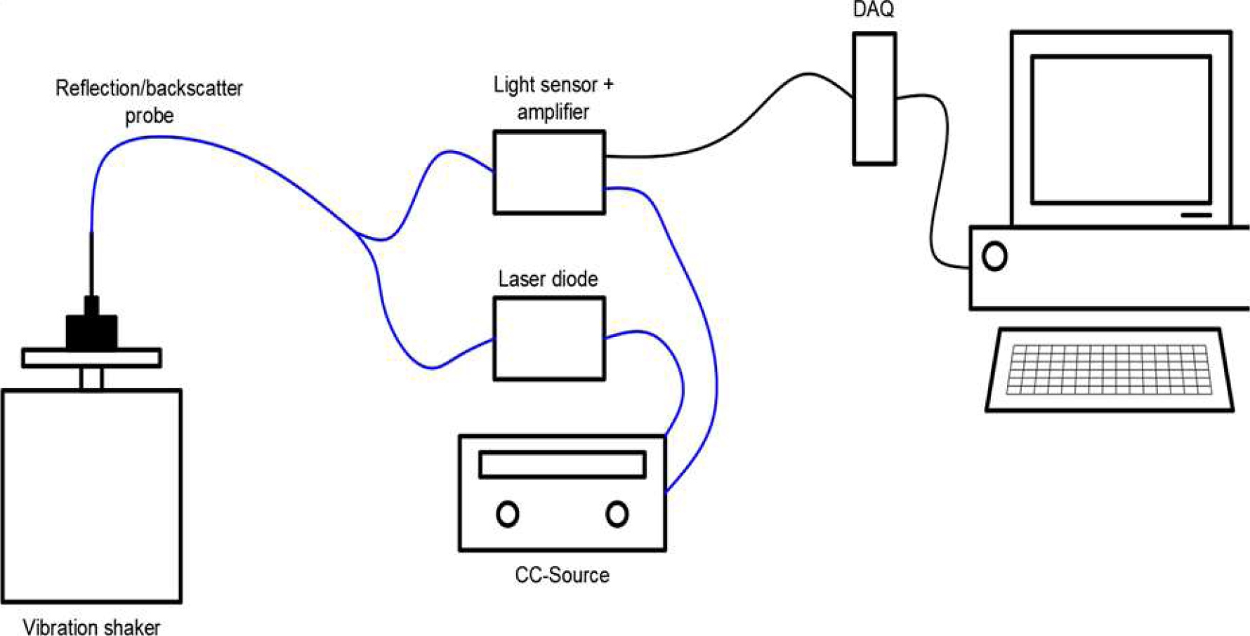
We used a NI-9232 board with a sample rate of 10k Hz and specific software testing for data acquisition. The one-optical-fiber-terminal of the reflection probe is attached to a laser diode for transmitting the light into the housing accelerometer.
Meanwhile, the multiple-optical fiber terminal collects the reflected light and is attached to the light sensor.
The stainless cylinder of the reflection probe is fixed to the accelerometer's housing, where the distance between the end-cylinder and the mirror is critical for establishing the highest beam reflection.
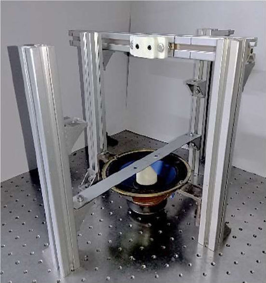
For testing, the vibration shaker (Fig. 6) consists of a small speaker fixed to an aluminum structure and driven into a frequency range between 25 to 300Hz with a sinusoidal signal. Finally, we compared the test results to an accelerometer DIN-LGA to verify their accuracy.
4 Results and Discussion
The initial tests let us select the best material for the new device. As mentioned above, four materials were tested, searching for the best approximation of the original signal in the vibration shaker, and tests were performed in the range from 10Hz to 300Hz with steps of 10Hz.
In a preliminary selection, PET and PVC were discarded. Fig. 8 shows a sample of the signal obtained in the tests made with the different materials using the 4-beam geometry (Fig. 4a), with the vibration shaker offset of 160Hz. The PET shows a worse response than the other materials in this figure.
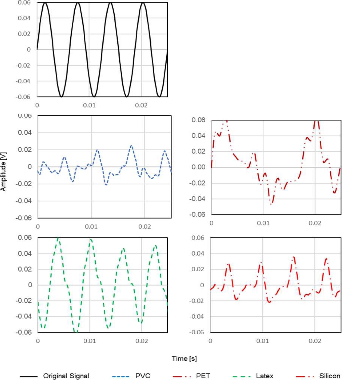
While Fig. 8 shows a similar response between PVC and silicon, Fig. 9 compares the response of these materials at different frequencies, where the last one enhances the signal response; considering this comparison, the PVC is discarded.
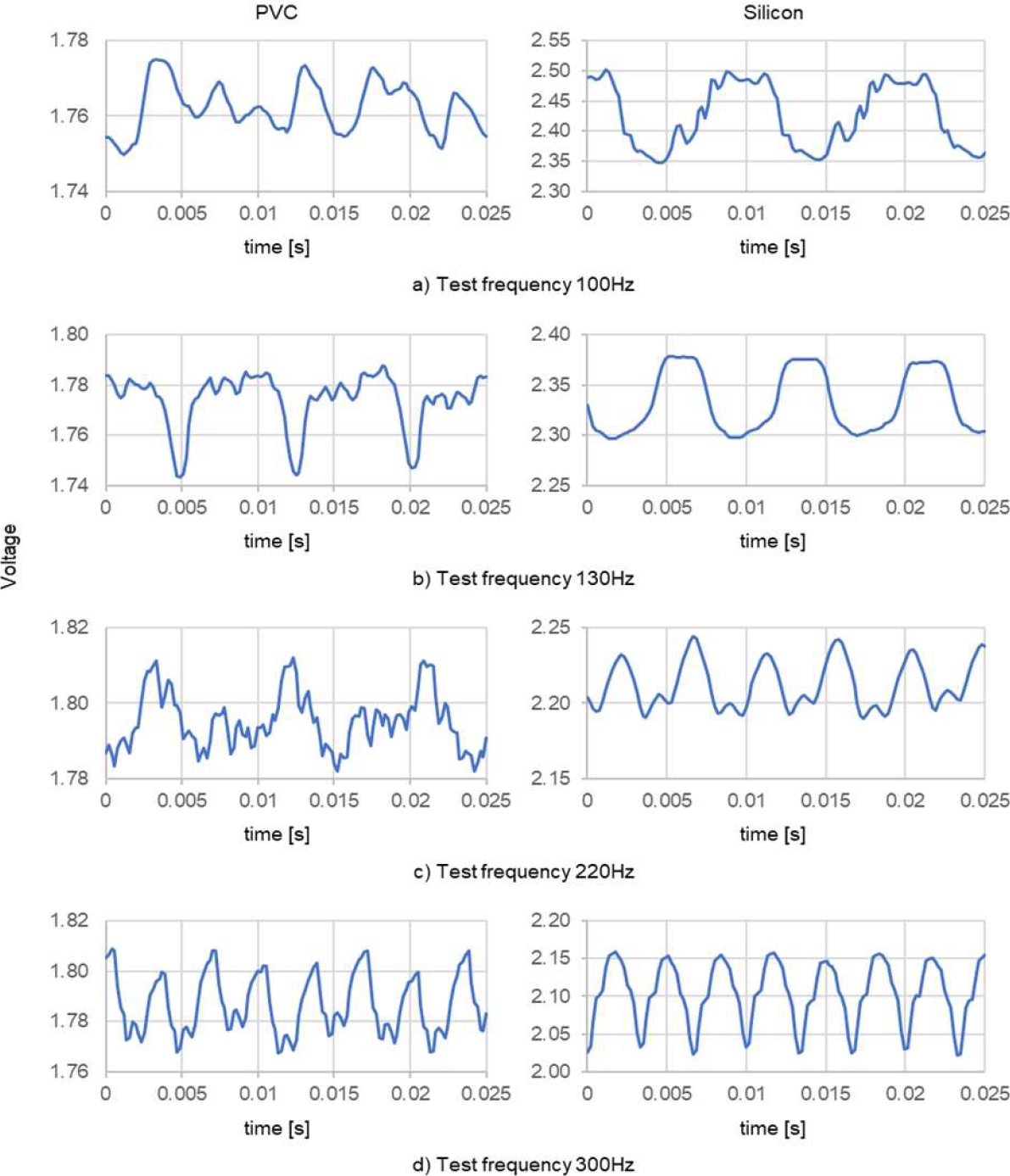
Fig. 9 Comparison between the response of PVC and Silicon at different frequencies using 4-beam geometry
The other two geometries shown in Fig. 4 (6-beam and 3-beam geometries) were tested to improve the results. Figures 10 and 11 show the response to combining the two remaining materials (silicon and latex) with the two geometries at different frequencies.
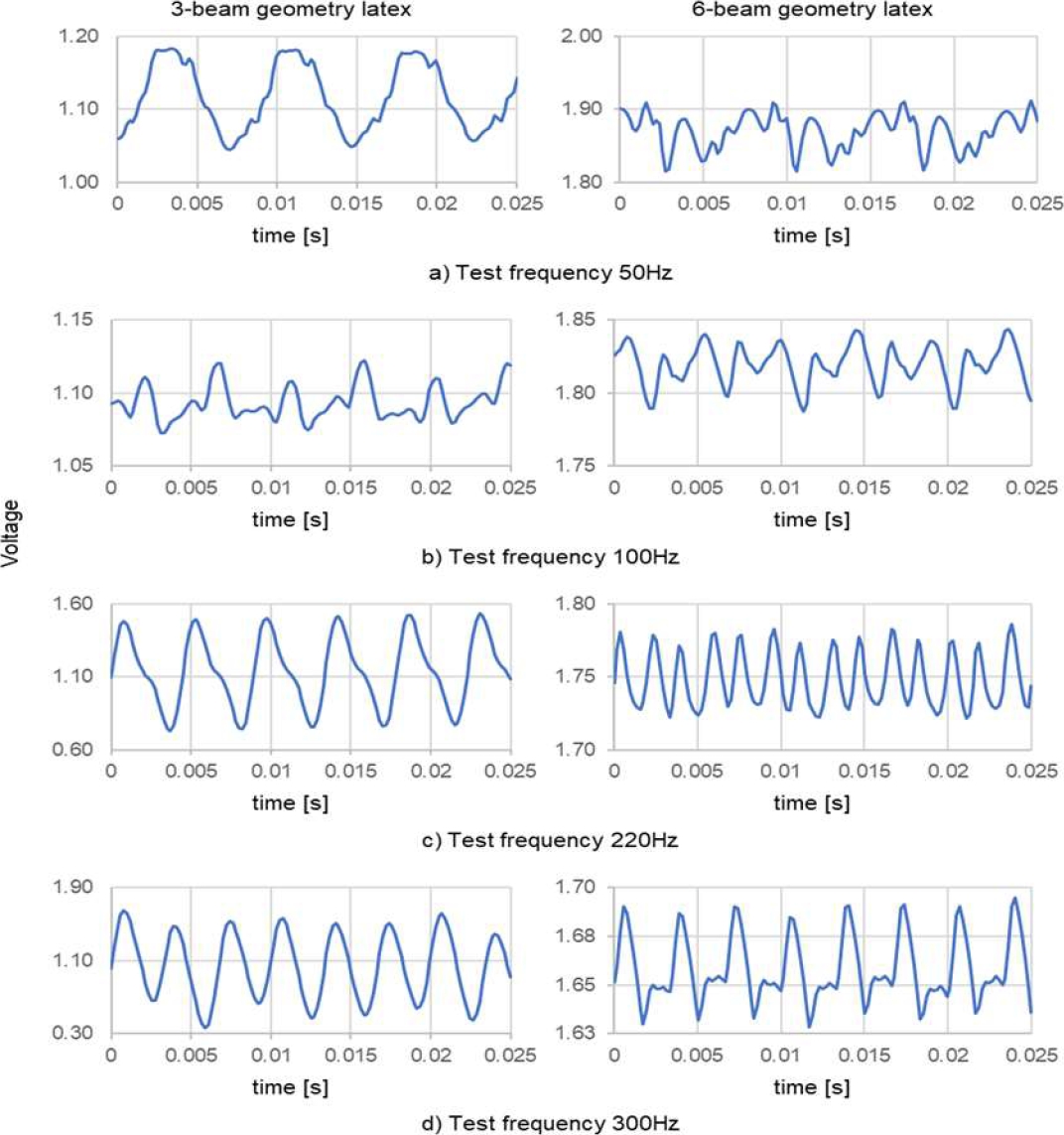
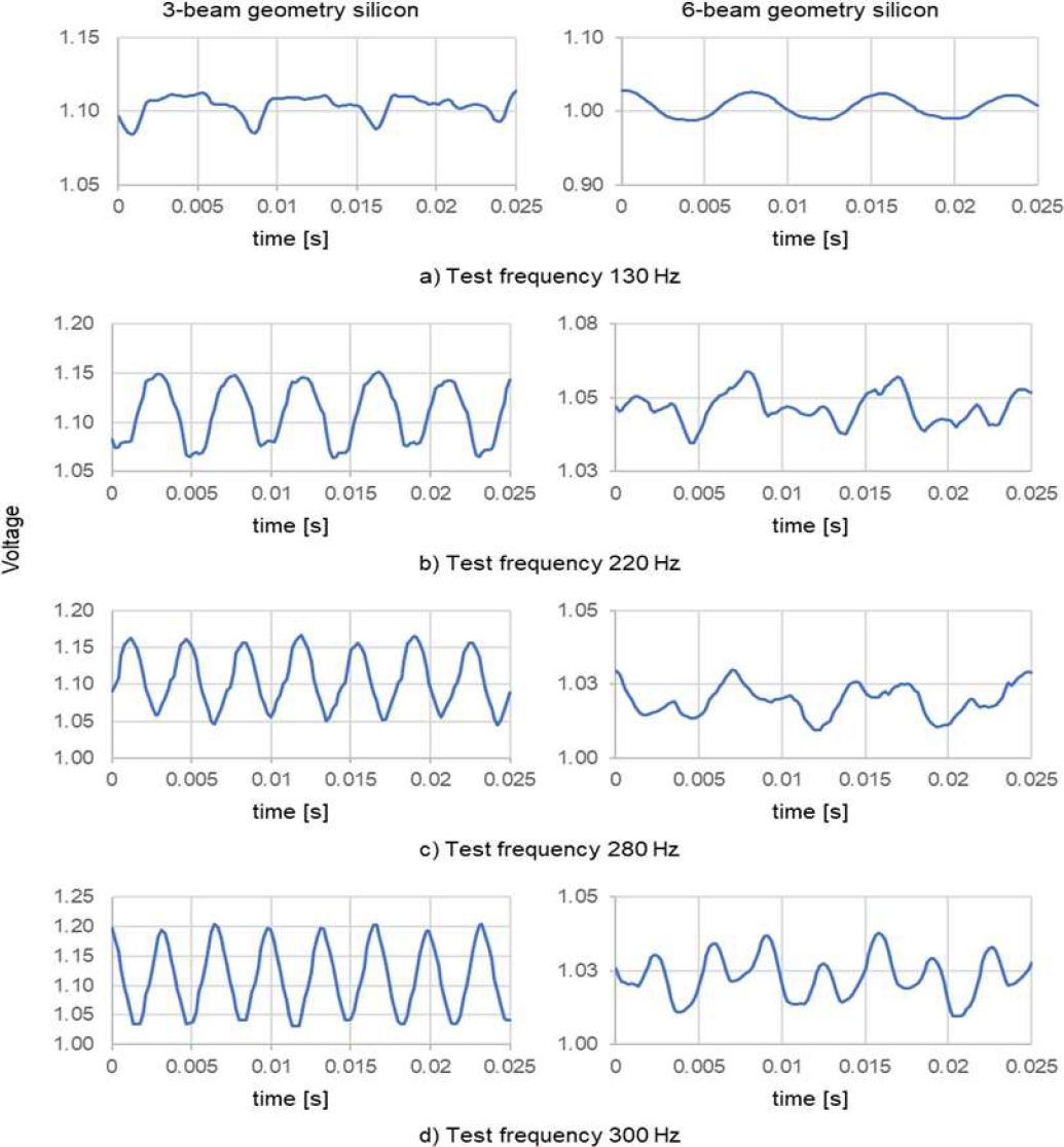
In both figures, considering the number of picks in the represented signal and the similarity to the original signal (a sinusoidal wave), the 3-beam membrane presents better results than the 6-beam membrane.
The fast Fourier transform (FFT) was applied to determine the frequencies of the acquired signals. Fig. 12 shows the main frequencies measured with the accelerometer compared to the signal frequency of the vibration shaker.
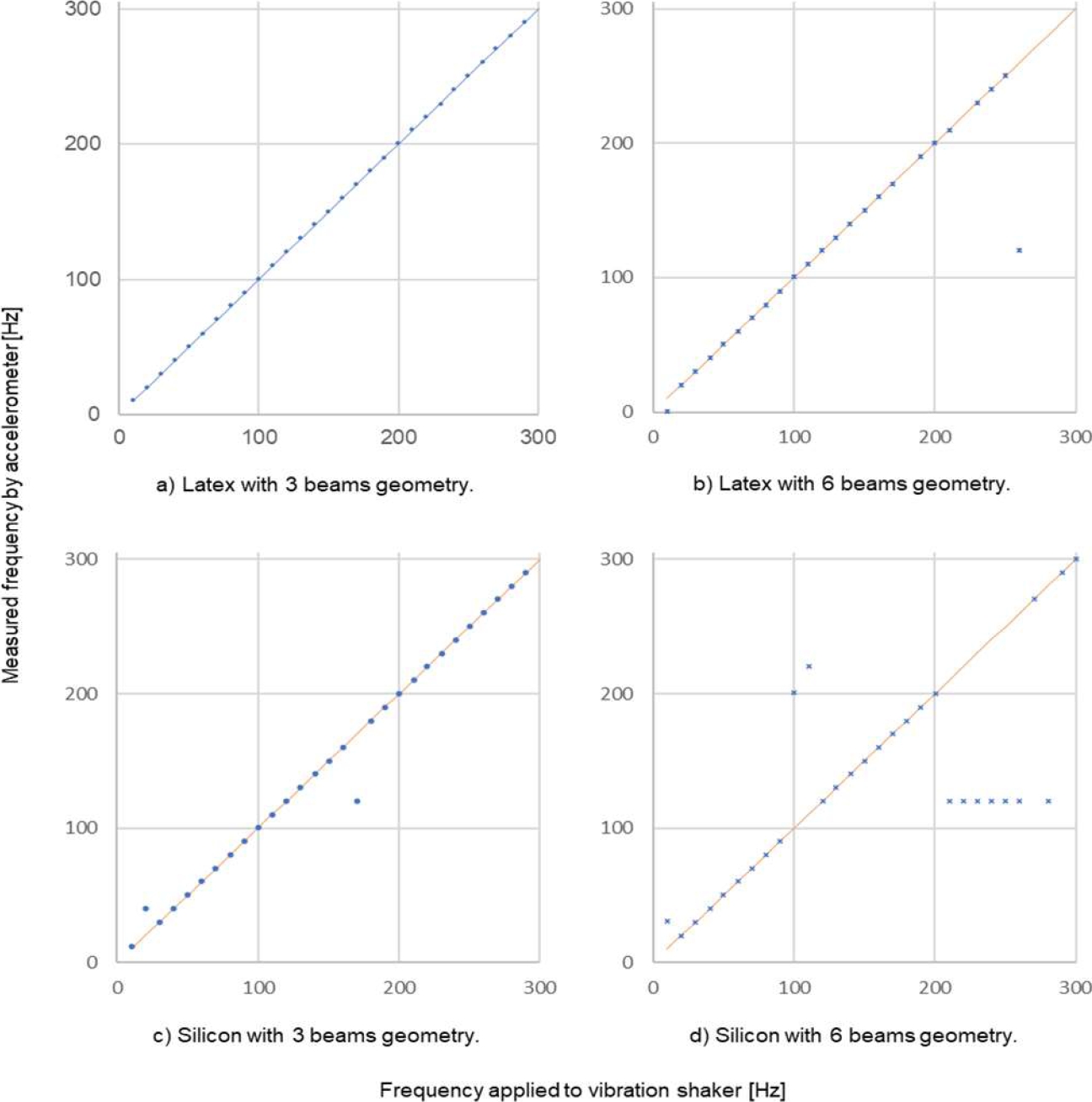
The central line indicates the expected result, meanwhile, the mark indicates the result of measuring, for example, in the first chart, all points are over the central line; in the other charts, some points are separated from the line indicating a difference between the main frequency measured and the vibration shaker frequency.
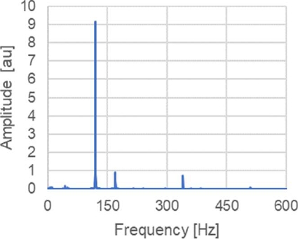
Nevertheless, it does not mean that the fundamental frequency is not detected. In Fig. 13, it is shown the FFT results of the 170Hz test using the 3-beam membrane of silicon. In this figure, the main frequency is at 119Hz, and the second one is 170Hz, which is the reason for the mark's position apart from the center line in Fig. 12.
The calculated average error for silicon membrane is 25.21% in 6-beam geometry and 5.03% in 3-beam geometry; on the other hand, for latex material is 28.44% with 6-beam geometry and 0.24% with 3-beam geometry. The average error was calculated considering the main frequency obtained by the FFT.
5 Conclusions
A unidirectional accelerometer has been developed under the mass-spring system, where an accessible, flexible material membrane has replaced the probe mass.
Tests showed that the geometry of the membrane has a more significant effect on the measurement results compared to the material used.
With the device tested, measuring the acceleration between 10 Hz and 300 Hz is possible, being the design of 3-beam geometry that presents better performance using latex material, considering the shape of the acquired signal and the main frequency obtained by the FFT.
In future work, to achieve more precise measurement results, it is necessary to improve the production of membranes and mirrors and new geometries.

