


 nueva página del texto (beta)
 Inglés (pdf)
 Artículo en XML
 Referencias del artículo
 Enviar artículo por email
 Citado por SciELO
  Similares en
SciELO
Similares en
SciELO 
 Permalink
1 Introduction
According to the World Health Organization (WHO) [1], the population in Latin America has aged at an accelerated rate in recent years. That implies an increase in the elderly population and in the health problems that they may have. One of the main problems (which affects not only the elderly) are disabilities. Among disabilities, according to COPRED (Committee to prevent discrimination in Mexico City) and INEGI (National Institute of Statistic and Geography) [2], problems with mobility are the most frequent, representing 60.2% of all people reported with at least one disability and close to 3% of the total population in Mexican capital. One of the main causes of disability in Mexico is the Rheumatoid Arthritis with a prevalence of 2.8% in the general population [20]. On the other hand, in Mexico, the infrastructure has never been designed for people who, for example, use a wheelchair, cane, or guide dog.
Although there is a Mexican Law on accessibility for people with disabilities since 2011 [3], which focuses on observing public policies aimed at equity, equal opportunities, inclusion, and accessibility in basic infrastructure and transportation of people with some kind of disability, for example, physical ones. It does not seem that a real solution has been found to improve their mobility.
In this sense, an intelligent wheelchair is an excellent solution to overcome problems of mobility of people with physical disabilities, for example, more freedom, mobility on difficult terrains (pavements and slopes), inclusion in social activities, and people’s autonomy.
In literature, we can find different approaches for the design of an intelligent wheelchair that is appropriate for the user [21-31]. All approaches use different sensors for data acquisition and control of the chair, in addition they use some microcontrollers capable of processing information. Naresh et al. [21] presented an Arduino-controlled wheelchair as an alternative using a joystick-based manual control.
Al-Okby et al. [22] reported a wheelchair where voice recognition and orientation detection-based controllers replaced the joystick and buttons. Besides, wheelchair tilt auto-calibrating, speed compensation, emergency stop, and command confirmation functions were implemented as additional functions. Kumar et al. [23] proposed a fully automatic wheelchair with obstacle detection through ultrasonic sensors and a tracking system using GPS. In addition, the wheelchair incorporates an automatic head mat controlled by a humidity sensor.
Luo et al. [24] designed a wheelchair using a single chip microcomputer for intelligent control, on the one hand for assisting wheelchair users to get up on it, and on the other hand as toilet assistance by collecting their bowel movements. In [25], Siddiqui et al. presented the development of a low-cost automated wheelchair that helps visually impaired people. The proposal uses machine vision techniques for localization and path planning using a braille keypad interface; and proximity sensors for obstacle avoidance. Daryani et al. [26] presented a modular system containing sensing and perception hardware with multi-modal sensors and software system design for autonomous and intelligent wheelchairs.
The main goal was to develop a full-fledged modular platform to test and deploy the latest deep learning-based algorithms. Nair et al. [27] proposed an intelligent wheelchair incorporating a computer and sensors.
The wheelchair is controlled by detecting the head movement through a headgear with a gyro sensor. Ahmed et al. [28] designed a wheelchair containing two types of drive systems: the thumb and gesture control systems.
In addition, a heart rate sensor measures the patient’s medical condition, generating an emergency notification if necessary. Sola-Thomas et al. [29] presented an open-source smart-wheelchair wheelchair as a customized version of a commercially manual one. The user can select if the wheelchair goes by navigating themselves through the joystick or automatically.
The system incorporates a stereo depth camera, LIDAR, motor controller, joystick, emergency switch, and a Jetson processor. In [30], Sandoval-Bringas presented the design and construction of an electronic device adaptable to a motorized wheelchair that serves as an intelligent navigation system. The wheelchair incorporates the control means head movements, voice commands, muscle flexion, and muscle contraction.
Pan et al. [31] proposed a method for connecting a smart device to a wheelchair using an accelerometer sensor. The wheelchair’s motion is controlled through head movement or with a smartphone application via Bluetooth. However, many of these electric wheelchairs are not easy and comfortable to use or operate for the seated user [19]. In addition, some of these wheelchairs can be very expensive [18].
In this work, we propose the development of a smart wheelchair for arthritic older adults (i.e., limited mobility due to weak arms and legs) able to move automatically by two ways: using a manual control through slight movements of the hand by joystick and using voice commands.
Also, the constraints of the wheelchair are threefold. It should be comfortable, be able to move on uneven surfaces (like indoors) without disturbing the user, and be low cost.
To accomplish this, we applied the general methodology for mechatronics design that implies the conceptualization and integration of the mechanics, electronics, and the IT/computing components.
For validation, we build a prototype and we test it in different real indoor scenarios. We anticipate that the proposal is a low-cost efficient smart wheelchair prototype that can be further considered for real technological solutions.
The rest of the paper is organized as follows. Section 2 describes the related work of smart wheelchairs. Section 3 presents the proposal design of the wheelchair. Section 4 includes the experimentation while Section 5 reports the results. Section 6 provides the discussion, and lastly Section 7 concludes the paper.
2 Related Work
In the literature, we can find many intelligent wheelchair developments. Although there has been an improvement in the design of smart wheelchairs, most of the designs are not implemented due to the cost, the complexity of manufacturing, or because they are still under development. The evolution of these works over the last 20 years is presented below.
The work by Kuno et al. [4] presents a robotic wheelchair that observes the user and the environment using a camera and sensors.
It can understand the user’s intentions from his/her behaviors and the environmental information. It also observes the user when he/she is off the wheelchair, recognizing the user’s commands indicated by hand gestures.
Currently the system detection can be modified to use the movements of the mouth, eyes, or any other body parts that they can move. This is a great advantage as the system of detection can be adapted to different users with a variety of physical disabilities and more users could have access to this resource.
In the work of Alcubierre et al. [5], the authors proposed a smart wheelchair that is controlled by voice commands. This wheelchair has two direct current (DC) motors which drive the rear wheels. The wheelchair has a computer screen to check the commands and it also has a microphone to give the inputs.
The most important advantage of this proposal is that the system avoids collisions with objects, and it can arrive at its destination through narrowed spaces. Some disadvantages are that the wheelchair follows commands of any voice, additionally it is not able to perceive the environment. Also, a voice-controlled wheelchair was developed by Nishimori et al. [6] to help disabled people. The main goal of the project was to avoid the muscle force required to operate a traditional manual wheelchair.
A laptop was used to execute the main commands. The authors concluded that the wheelchair produces very effective results when executing commands. One disadvantage is that it does not consider obstacle avoidance.
Next, the Omnidirectional Stereo VisionBased Smart Wheelchair, developed by Satoh & Sakaue [7], detects both the potential hazards in a moving environment and the postures and gestures of a user by equipping an electric wheelchair with the stereo omnidirectional system (SOS).
To use the multi-camera system SOS on an electric wheelchair, the authors developed an image synthesizing method of high speed and high quality, and a method for recovering SOS attitude changes by using attitude sensors. This is advantageous because the system has a storage of different user positions through which the system can respond without confusion to know the specific situation of the patient and the electronic system can act directly.
The limitation of the proposal is the high cost of the equipment because a video system of high video quality is necessary for the processing of the user’s situation and, therefore, it also has a complex control system.
In 2009, Purwanto et al. [8] developed an electric wheelchair controlled by gaze direction and eye blinking, where a camera is set up in front of the user to capture image information.
One of the advantages is that it can be controlled only with the eyes and the face without lifting a single finger, which is of great benefit for people who have become quadriplegic.
However, the limitation lies on the operation, especially since it can be very difficult to take care of each expression that the user makes with his/her face.
Gómez and Medel [9] proposed a prototype of an intelligent wheelchair controlled by means of easy gestural instructions.
The robotic prototype hardware was designed with a PIC16F877A microcontroller as control devices, and some sensors like analog presence sensors, analog light sensors, and a digital webcam sensor.
Gestures were determined by the position of the eyebrows, eyes, and mouth. Tomari et al. [10] proposed a semi-autonomous control wheelchair system with a multi-input interface to aid mobility of people with severe motor impairment.
The system is implemented on an electric wheelchair and it is equipped with a switch and four types of sensors (a standard webcam, a RGBD Camera-Kinect, a laser range finder and an Inertial Measurement Unit sensor IMU).
The wheelchair has two control modes: the manual mode and the semi-autonomous mode. The user can change the modes freely by manual switch operation (incorporating a safety map, the wheelchair can avoid collision in both modes).
The most important advantage is that the system allows users with severe motor impairment to operate a wheelchair when they are in tight space (passing doorway) or when avoiding obstacles. Also, it provides independence, because the critical and dangerous situation is effectively overcome, but at the same time the user is still feeling that he/she is driving the wheelchair.
Morales [11] proposed a mechanism to move a wheelchair by means of a mobile device, as they highlighted the inability to recreate a physical environment for all people in wheelchairs.
The aim of this work was to develop a control system to apply it to a wheelchair, which was aimed at promoting the quality of life of people who use this device. The control system responds by means of a mobile device, using a touch screen.
The greatest advantage of the system is that it can be applicable to any non-intelligent wheelchair, however it does not consider the point that many people using this type of electronics chair can feel equally uncomfortable and the batteries it uses are not rechargeable.
Cifuentes et al. [12] developed a system that can turn a traditional electric wheelchair into a” smart wheelchair”. This system consists of the design and implementation of a microcontroller that can process different types of environmental signals that produce automatic movement outputs so that the wheelchair moves in a specific path.
The authors claimed that the device is easy to adapt to any manual chair to make it electric. The system can change from 4 to 2 support wheels that allows it to overcome obstacles more easily using fuzzy-logic controllers.
One advantage is that it obtained efficient results when checking the user’s vital signs in 95% of the cases. A weakness of the work is that the number of bits used to design the processing card was not enough to achieve its overall goal.
Table 1 summarized the above smart wheelchairs found in the literature. As shown, their controls are mainly based on: the user’s gestures like the movement of the face or another part of the body, the voice, and by joystick/buttons/touch-screen commands.
Table 1 Examples of smart wheelchair projects reported in the literature
| Sensors | Type of Drive Control | Hardware Platform | Features | Study Place | |
| [4] | Environment Observing Camera User Observing Camera 16 ultrasonic sensors |
Face Direction Control Hand Gestures Commands |
PC (AMD Athlon 400 MHz) | − Environment Observation − Autonomous Capabilities − Understanding of User’s Intentions − User facial recognition − Avoid Obstacles − Two Control Modes |
Kyowakai Hospital Laboratory |
| [5] | Laser sensor Microphone |
Voice Control | PC 1 (Pentium MMX 266 MHz) PC 2 (Pentium III 850 MHz) |
− Voice Controlled − Autonomous Movement System − Visual System for Information − Paths Planning − Obstacle Detection and Avoidance − Available on Difficult Maneuverability − Remote Control |
Office |
| [6] | Headset microphone | Control button Voice Control |
Base system (Wheelchair NEO-P1) Laptop |
− Visual Display − Misrecognition Verification System −Two Type of Controls: Voice or Button |
Laboratory Room University Campus |
| [7] | Stero Omnidirectional System - SOS (36 cameras arranged in dodecahedron shape) Gyro-sensor Acceleration sensor |
Joystick Control Voice Control Gesture Detection |
PC of 3.6-GHz CPU | − The implementation is in an electric wheelchair − Detect potential hazards, postures and gestures − The system with high frame rate − Stereo omnidirectional system − Posture detection alarm system |
Office |
| [8] | Camera | Gaze Direction Eye Blinking | Not Mentioned | − Safety, Timing, Direction and Velocity Control − Commands by Positions of the Eyes and the Nose |
School Lab |
| [9] | Analog Presence sensors Analog Light Sensors Digital Webcam Sensor |
Easy Gestural Instruction | PIC16F877A | − Only Control Method, not Applied on Wheelchair − Gesture Control Focusing on Mouth, Eyes and Eyebrows |
School Lab |
| [10] | Webcam RGBD Camera - Kinect Laser Range Finder Inertial Measurement Unit sensor-IMU |
Motion of Fatial Parts Voice Joystick |
Not Mentioned | − - Three Control Modes − - Several Maneuvering Modes: “Stop”, “Semi-auto”, “Manual” |
Laboratory Room |
| [11] | Not Mentioned | Touch Screen of Mobile Device | Arduino UNO | − Control by Mobile Device with Android − Includes Power Circuit |
School Lab |
| [12] | Commercial Models Sensors are not specified Heart Rate Sensor Differential Pressure Sensor |
Automatic Path Generator Joystick |
PIC18F4550 | − Vital signs measurement. − Operational modes: Configuration, Joystick and Automatic − Manual movement stop Sensor |
Research Room |
| Ours | Ultrasonic Sensors Microphone |
Joystick Control Voice Control |
Arduino Mega | − Easy Adaptation to any Wheelchair − Detect Obstacules − Emergency Stop − Two Control Modes: Joystick Control or Voice Control Commands (Fordward, Backward, Right, Left, Stop) − Low Cost |
House Interior − Living Room − Bedroom |
Further, the hardware platforms used are robust systems such as personal computers (PCs), laptops, and microcontrollers. Lastly, the literature reports limited test experiments, emphasizing tests in controlled conditions, which it turns difficult to assess the overall performance of the wheelchairs in real-world conditions.
From the above, our proposal consists of a selection of controls easy to use (i.e., joystick and voice commands), but also simple to process by the hardware platform. Consequently, the unit processing platform might be cheap. Moreover, our wheelchair considers a set of sensors for perceiving the environment such as obstacles, allowing the user to drive safely and comfortably.
Lastly, we test our wheelchair in real-world conditions, for example indoors with different obstacles. The proposal is presented next.
3 Description of the Proposal
We propose a smart wheelchair that can interact with the user by manual operation using a joystick or voice commands. In addition, the wheelchair can move around indoors with some dynamic objects, and for this purpose, the wheelchair is equipped with ambient sensors.
Also, the smart wheelchair should be as low-cost as possible in terms of the materials. In a nutshell, the smart wheelchair functionality is described as follows: after turning it on, an operation mode is selected (manual or by voice control), then the joystick movement or voice command is received (depending on the previous selection), and the indicated direction is followed by the wheelchair with the activation of motors and according to obstacles perceived (using the ambient sensors) in the environment.
The technical components of the wheelchair are then mapping from the inputs and the outputs required and from the expected functionality, as shown in Figure 1.
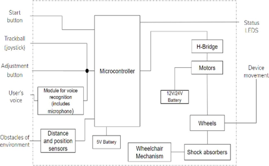
The details of these components are described next according to the mechanics, electronics, and IT/control elements of the wheelchair.
3.1 Mechanical Components
First, the mechanical parts for the structure and motion compatibility with the desired functionality are proposed in Figure 2. As shown, it comprises a structure resembling the seat, the backrest, and the support for the wheels and the electronics components.
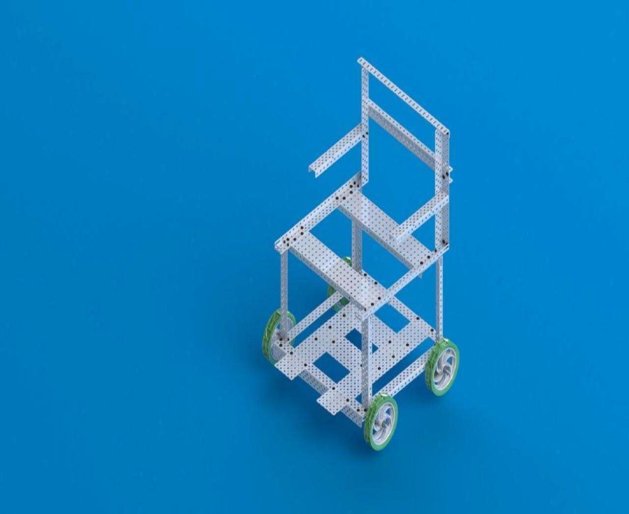
It is proposed to use the parts that are included on the VEXRobotics kit as raw material, because they are light and easy to build. In Figure 2, the 3D CAM model is shown, with a scale of 1:2.
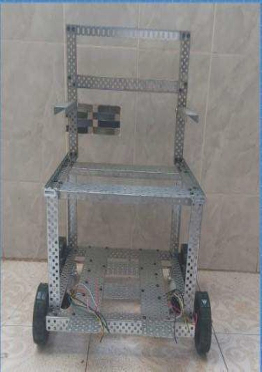
From the above, a prototype is implemented, including two geared motors of 105 rpm with 5A, 12V. The result is shown in Figure 3 with dimensions: 52.705 cm of total height, 31.750 cm of total width, and 33.020 cm of total length.
3.2 Electronic Components
For the electronic parts, we decided to use two DC gear motors (GW4058); two drivers (Vnh2sp30); three transceiver modules (nrf24I01); one joystick shield v1.a; two Arduino UNO; one Arduino Mega; on voice recognition module; six ultrasonic distance sensors; and two batteries (12V 7 Ah and 9V).
As it can be seen in the schematic circuit of Figure 4, we use the Arduino Mega to control the motors and read the distance sensors. We use a transceiver module (nrf24I01) to have SPI communication between this Arduino Mega and the instructions commanded.
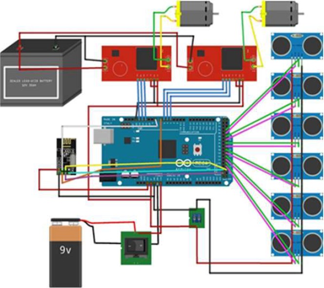
When the microcontroller gets an instruction, it sends a signal to the H-bridges to move the motors. Furthermore, we have two batteries, the first (9V) gives energy to the Arduino Mega, the distance sensors, and the transceiver module; while the other battery gives enough energy to move the motors.
Figure 5 shows the connections for the voice recognition module. We use a 9V battery to feed the Arduino UNO. We also have the transceiver module (nrf24I01) to send the instructions.

3.3 Control & IT Components
The control system was designed on the rear wheel motors in order to control the angular speed of the wheels according to a certain voltage input. The plant transfer function was obtained based on the general transfer function of the DC motor between the angular displacement of the motor and an input voltage [13]. The number of teeth of the gears was related and the resulting transfer function was derived in the s domain to obtain the desired transfer function between the angular displacement of the wheels
A usual desired speed for an electric wheelchair is around 6
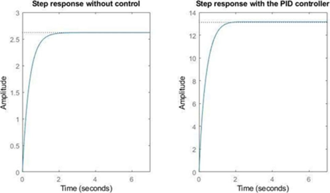
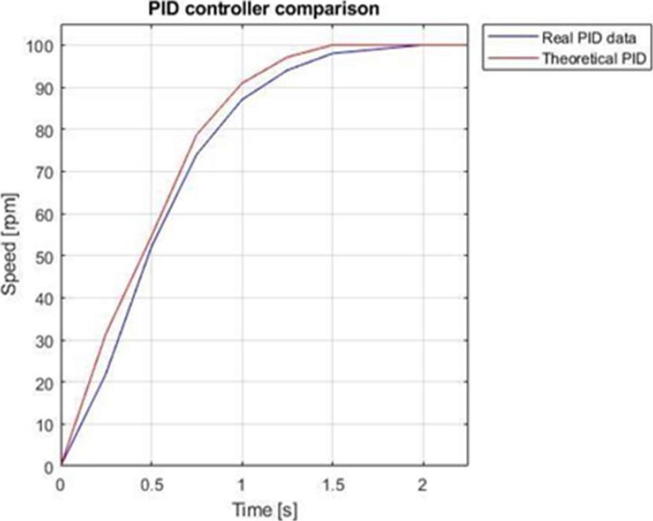
The closed loop response of the system with a step input of the desired magnitude was analyzed in order to determine the appropriate controller. A PID controller was designed using Matlab Simulink to fulfill the requirements (to reduce the steady state error and the settling time).
A comparison of the step response of the uncompensated system (without controller) and the compensated system is shown in Figure 6.
3.4 Smart Wheelchair Simulation Integration
3.4.1. Mechanical and Control Simulation
A movement study in SolidWorks was carried out for the rear wheels to corroborate the integration of the mechanical control component.
The function of the angular velocity of the wheels compensated with the PID controller in the time domain was obtained to take as input in SolidWorks to see the real behavior of the speed of the wheels. Figure 7 shows the results obtained for the angular velocity
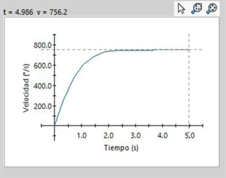
From the movement study, available in Solidworks document, it can be known that the angular velocity of establishment will be 751.9 °/s, this represents more than two turns of the rear wheel per second (considering the maximum linear velocity of 6 km/h). However, it is worth mentioning that surely our wheelchair is going to work at a lower speed.
3.4.2. Integration of Electronic Operation
The software Tinkercad was used to simulate the electronic part of the project. For the electronic simulation, we used three ultrasonic sensors, two DC motors, one power source, an Arduino UNO, one H-bridge, one potentiometer (it represents the joystick), an alarm, and one switch, as shown in Figure 8.
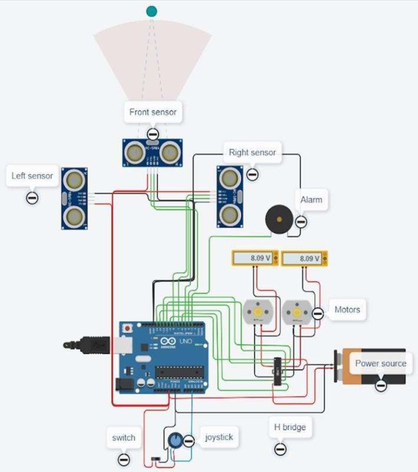
It can be seen in Figure 9 that we can control the power of the motors depending on the direction of the joystick.

Fig. 9 Electronic simulation when the ultrasonic sensor detects an object (left) and Electronic simulation when the joystick is on and it points diagonally (right)
It means that if we point to the right, the right motor will lose power, proportionally to the angle of the joystick, while the left motor will have the maximum power, it will let us turn to the right as fast as we want and make our trajectory as we want. When one of the sensors detects an object and the joystick points in the same direction as the sensor, the alarm makes a sound to make the user know about the obstacle and both motors have to be stopped to avoid crashes with objects.
3.4.3. Complete Assembly Integration
Once all the necessary components have been completely simulated, the final integration of the wheelchair can be carried out, mainly on two fronts: the electronic and the mechanical components. The result is shown in Figure 10. Six distance sensors are placed on wheelchairs at low altitude in order to identify objects on the floor. Particularly, two of these sensors at the front and two at the back, since the wheelchair is more likely to crash in either of these two directions. A complete detail of the electronic system integration in the structure is depicted in Figure 11.
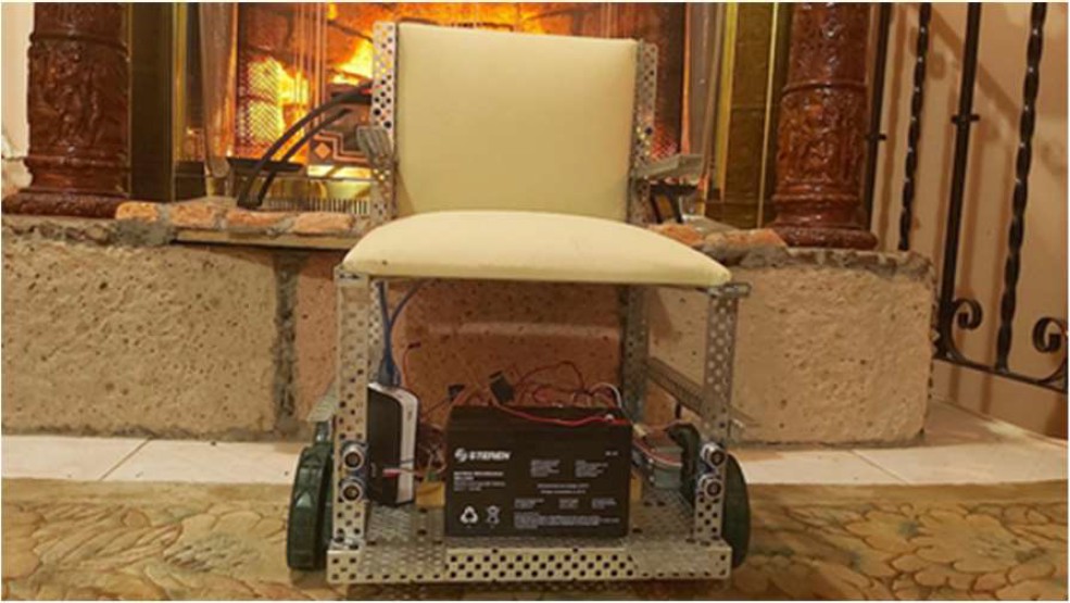

Fig. 11 Electronics integrated in the wheelchair (top view without seat). A (dark blue): Arduino Mega; B1 (purple): Power Battery for motors; B2 (green): Power Battery for Arduino; C (yellow): Printed circuit for Arduino; H1/H2 (salmon): H-Bridge/PWM; M1/M2 (red): Motors; P (orange): Auxiliary Protoboard; R (sky blue): Receptor; S1-S6 (aquamarine): Distance Sensors; X (brown): Box container for electronics
4 Experimentation
4.1 Real Control Setting Parameters
For the determination of the real control plant, the PWM signal was increased by 20 units at each 0.25 second sampling time step (which would represent a 20 slope ramp input for the system) until the motor reached steady state speed.
The maximum angular speed of the motor connected to a 12V battery is 150 RPM. After getting the results a regression analysis was made to get an equation of the speed of the motor as a function of time.
Once the equation of the speed was obtained, to get the adjusted transfer function Laplace transform was applied getting an expression for the speed response to a ramp input
This equation is the adjusted version of the theoretical equation considering the real response of the motor. The magnitude of the step input was also readjusted to be 100 rpm. Then (2) was brought to Simulink to obtain the new values of the control constants:
4.2 PID Implementation
Once the controller was designed, it was implemented in the motor using an Arduino MEGA. Figure 12 shows the comparison between the real PID results obtained with the Arduino MEGA and the Matlab PID data from the control system of equation (2). The maximum percentage of error with respect to the theoretical results was 27.9 %, but as time passes, the error decreases until the reference is reached in both cases.
4.3 Functionality Testing
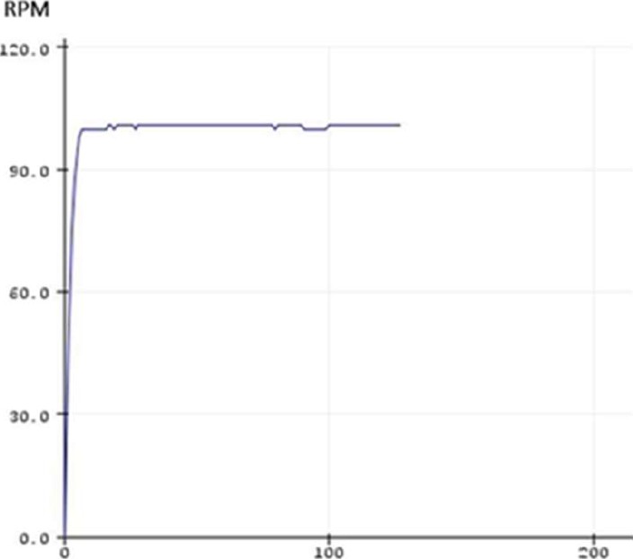
All the design and implementation of the PID controller was carried out. A test program to Arduino MEGA was run and the response was measured with the PID controller on Arduino plotter, but already with full integration. The result can be seen in Figure 13. As shown, the speed of the motors is very similar to PID controller performance and continues to reach approximately 100 RPM, even when they are already assembled to the wheels on complete wheelchair.
4.4 Devices for Control Experiment
It is important to ensure that the wheelchair always responds correctly to commands (for both joystick and voice commands). For this, we have as a controlled factor the device to use: joystick or voice commander. Then, every measure will be evaluated if an instruction is correctly received or not (Correct = 1/Incorrect = 0).
The commands that the wheelchair can receive are indicated in Spanish: Adelante (forward); Atras (backward); Derecha (right); Izquierda (left); and Alto (stop). Twenty-five random instructions will be sent to the wheelchair per each control mode (joystick or voice command).
After that, we could determine which is the most reliable device to control the wheelchair (Figure 14).

4.5 Switching Voice Commander Experiment
The goal of this experiment is to verify the effectiveness of the wheelchair to be controlled by different people through their own voice. We have as a controlled factor the kind of people, which will control the wheelchair.
Then, four people with different characteristics are evaluated: 27-year-old man; 29-year-old woman; 58-year-old woman; and 66-year-old man. Like previous experiments, when the instruction is correctly received, it will be established as 1, but if it does not, it will be established as 0.
This experiment will be planned to avoid external noises, however the sound generated by the motors of the wheelchair itself could represent an uncontrolled factor. Two women and two men communicate 15 random instructions one by one, as exemplified in Figure 15.

4.6 Performance with Different Load Weight Experiment
In this experiment, we want to analyze how different load weights affect the performance of the average speed of the wheelchair and determine the maximum extra load that it can carry. Approximately, wheelchair weight without load is 5kg. This experiment consists of moving the wheelchair in a straight line for 3 meters while timing in order to calculate speed.
Later, after completing 15 measurements, an extra 1kg will be added and the procedure will be repeated, until reaching 5kg. With this, it is possible to obtain the average speed of the wheelchair in each treatment and observe how the different loads affect or not their performance. Figure 16 shows the layout of the experiment.

4.7 Automatic Stop by Distance Sensors Experiment
This experiment measures the most convenient distance to stop the wheelchair by ultrasonic sensors. The experiment consists of moving the wheelchair in a straight line for 2 meters (at this moment, it reached its maximum speed).
Also, an obstacle (a box) will be previously placed on their way, the wheelchair is supposed to stop automatically, even though the joystick is still activated. At the end, the real distance between the sensor and the obstacle will be measured (Figure 17). This process will be repeated 15 times per event.

4.8 Wheelchair Complete Performance
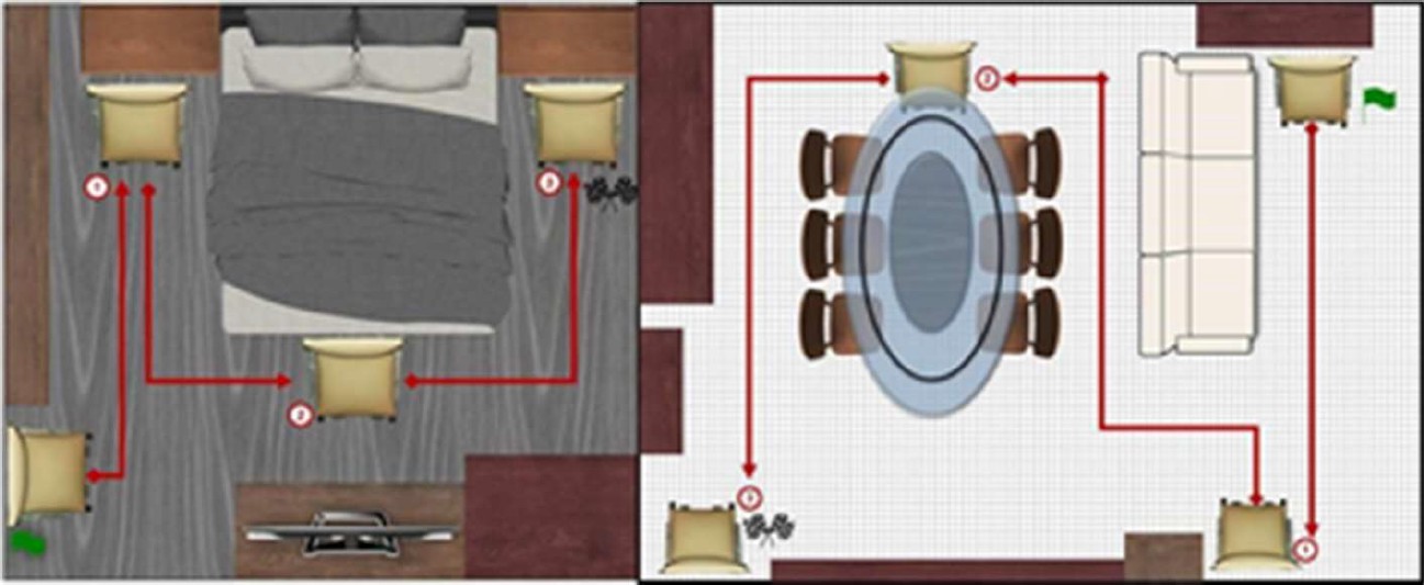
In this experiment, the goal is to determine the effectiveness of the use of the wheelchair to move indoors by both means of control: joystick and voice commands, avoiding collisions and identifying where it has the best performance. This experiment consists of designing a route within each designated space: dining-living room and bedroom.
On each route, the following will be identified: a starting position and three sequential goal positions (in each position the wheelchair must have a desired orientation). The wheelchair should move through the space following that route, controlled by voice or by joystick.
Each treatment will be done 15 times. If the wheelchair reaches the correct position and orientation correctly, it will score a point. So it could get up to a maximum of 3 per measure (1 for each correct position).
If it collides or needs human intervention to continue, a point will be subtracted (the minimum value of the measurement will be zero in any case). Figure 18 shows the layout of the actual dining living room and bedroom on which the wheelchair will move.
5 Experimental Results
5.1 Devices for Control Experiment
Figure 19 shows the results based on treatments and procedures explained previously. According to the results, the joystick control only failed 3 times out of 25 attempts, while the voice controller failed 7 times.

The interpretation of the standard deviation must be done with care, since there are only two possible values in the input (true and false). However, at first impression, it appears that there is greater accuracy in joystick control with 0.33 versus 0.46 of voice controller.
Therefore, although the wheelchair has a higher effectiveness when controlled by a joystick, in general terms its behavior and that of voice control is very similar.
5.2 Switching Voice Commander Experiment
From Figure 20, it seems that gender is the main factor that modifies the operation of the wheelchair by voice, although after age. Remembering that the module is programmed by a 22-year-old young adult man, the effectiveness is greater for the 27-year-old man and the next is the 66-year old man.

Both women are very close to 50% effective, which is counterproductive when using the wheelchair by voice.
5.3 Performance with Different Load Weight Experiment
Figure 21 shows the results correlating the speed versus the load weight. As it can be seen, the average speed decreases as 1kg is increased. However, the diminishing of speed is not so significant, since from 0 to 5 kg, it does not decrease more than 10 cm/s.

5.4 Automatic Stop by Distance Sensors Experiment
The objective of this experiment is to find which is the most convenient distance to stop the wheelchair by ultrasonic sensors. Figure 22 and Figure 23 show these results.

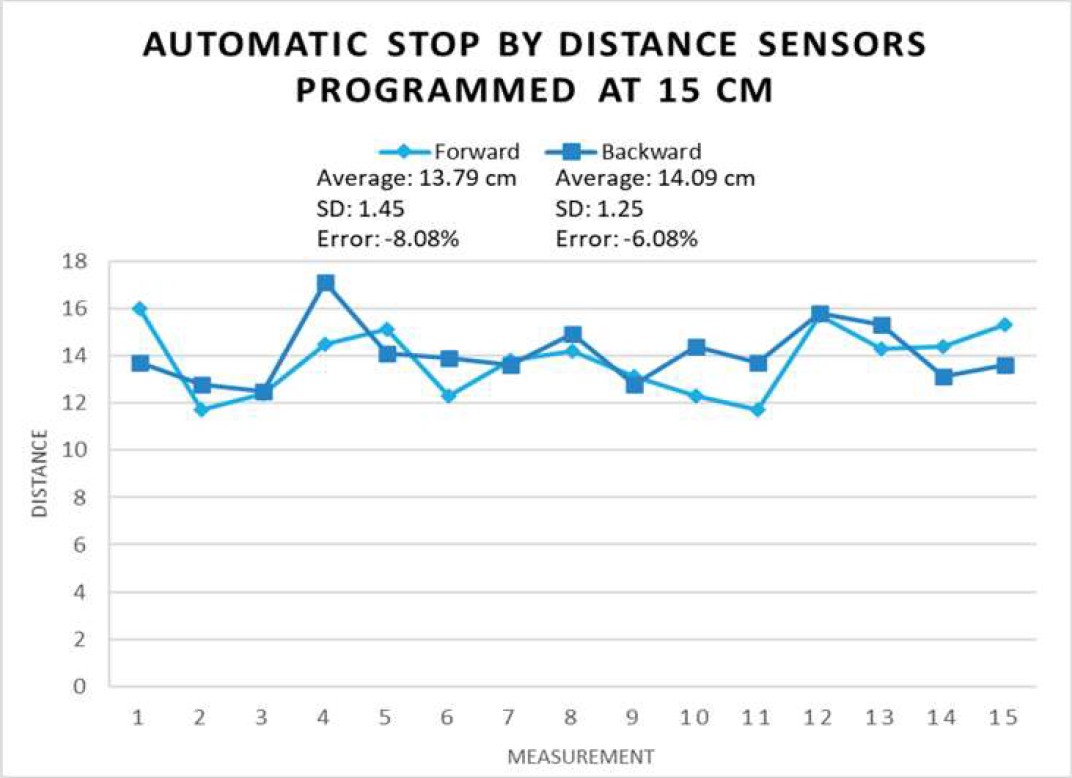
The values of the error were calculated relative to the expected distance according to stop thresholds in sensors (10 or 15 cm).
We can realize that when the distance is determined in 10 cm, it has a more precise performance than with 15 cm, reaching a error less than 2% on both cases (forward and backward).
Also, it seems that the sensors in the back respond a little better than those in the front, because comparing them with their respective treatment, backward movement is more accurate.
5.4 Wheelchair Complete Performance
In this experiment, the objective is to determine the effectiveness of the use of the wheelchair to move inside a house by both means of control: joystick and voice, avoiding collisions and identifying where it has the best performance.
Table 2 shows the Total column on the tables, the points at which the wheelchair reached the specified position are added (1 = achieved, 0 = not achieved) and the collision column is subtracted (one point less for each crash or human intervention, 0 = no problem).
Table 2 Treatment I: dining-living room with joystick controller results
| Treatment I Dining-Living Room with joystick | |||||
| Measurement | Position 1 | Position 2 | Position 3 | Collisions | Total |
| 1 | 1 | 0 | 1 | 0 | 1 |
| 2 | 0 | 1 | 0 | 1 | 0 |
| 3 | 1 | 0 | 0 | 0 | 1 |
| 4 | 1 | 1 | 1 | 0 | 3 |
| 5 | 1 | 1 | 0 | 1 | 1 |
| 6 | 1 | 1 | 0 | 1 | 1 |
| 7 | 1 | 0 | 1 | 0 | 2 |
| 8 | 1 | 1 | 1 | 0 | 3 |
| 9 | 1 | 0 | 1 | 0 | 2 |
| 10 | 1 | 1 | 1 | 1 | 2 |
| 11 | 1 | 1 | 1 | 1 | 2 |
| 12 | 1 | 1 | 0 | 0 | 2 |
| 13 | 1 | 0 | 1 | 1 | 1 |
| 14 | 1 | 1 | 1 | 0 | 3 |
| 15 | 1 | 1 | 0 | 1 | 1 |
| Average | 0.9333 | 0.6666 | 0.6 | - | 1.7333 |
| Effectiveness | 93.33% | 66.66% | 60% | - | 57.76% |
| Standard Deviation | 0.2582 | 0.4879 | 0.5071 | - | 0.7988 |
Tables 2–5 show the results for each treatment. Additionally, graphs in Figures 24–27 shows, for each experiment, a global performance of the treatment. As can be seen on the previous tables and figures, even though the behavior is similar and none is significantly better than the other, it can be determined that the wheelchair performs better in more open spaces than in tighter turns. In addition, the effectiveness increases if the joystick is used instead of the voice controller.
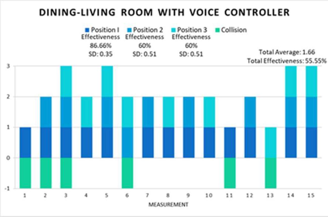
Table 3 Treatment II: dining-living room with voice controller results
| Treatment II Dining-Living Room with voice controller | |||||
| Measurement | Position 1 | Position 2 | Position 3 | Collisions | Total |
| 1 | 1 | 0 | 0 | 1 | 0 |
| 2 | 1 | 1 | 0 | 1 | 1 |
| 3 | 1 | 1 | 1 | 1 | 2 |
| 4 | 1 | 0 | 1 | 0 | 2 |
| 5 | 1 | 1 | 1 | 0 | 3 |
| 6 | 0 | 1 | 1 | 1 | 1 |
| 7 | 1 | 1 | 0 | 0 | 2 |
| 8 | 1 | 0 | 1 | 0 | 2 |
| 9 | 1 | 1 | 0 | 0 | 2 |
| 10 | 1 | 0 | 1 | 0 | 2 |
| 11 | 1 | 0 | 0 | 1 | 0 |
| 12 | 1 | 1 | 0 | 0 | 2 |
| 13 | 0 | 0 | 1 | 1 | 0 |
| 14 | 1 | 1 | 1 | 0 | 3 |
| 15 | 1 | 1 | 1 | 0 | 3 |
| Average | 0.8666 | 0.6 | 0.6 | - | 1.6666 |
| Effectiveness | 86.66% | 60% | 60% | - | 55.55% |
| Standard Deviation | 0.3519 | 0.5071 | 0.5071 | - | 1-0465 |
Table 4 Treatment III: bedroom with joystick controller results
| Treatment III Bedroom with joystick | |||||
| Measurement | Position 1 | Position 2 | Position 3 | Collisions | Total |
| 1 | 1 | 1 | 1 | 0 | 3 |
| 2 | 1 | 1 | 0 | 0 | 2 |
| 3 | 0 | 1 | 1 | 0 | 2 |
| 4 | 1 | ‘ | 1 | 1 | 1 |
| 5 | 1 | 1 | 0 | 0 | 2 |
| 6 | 1 | 1 | 1 | 0 | 3 |
| 7 | 1 | 1 | 1 | 0 | 3 |
| 8 | 0 | 1 | 0 | 0 | 1 |
| 9 | 1 | 1 | 1 | 1 | 2 |
| 10 | 0 | 1 | 1 | 0 | 2 |
| 11 | 1 | 1 | 1 | 0 | 3 |
| 12 | 1 | 1 | 1 | 0 | 3 |
| 13 | 1 | 1 | 1 | 0 | 3 |
| 14 | 1 | 1 | 1 | 0 | 3 |
| 15 | 1 | 1 | 1 | 1 | 2 |
| Average | 0.8 | 0.9333 | 0.8 | - | 2.3333 |
| Effectiveness | 80% | 93.33% | 80% | - | 77.77% |
| Standard Deviation | 0.4140 | 0.2582 | 0.4140 | - | 0.7237 |
Table 5 Treatment IV: bedroom with voice controller results
| Treatment IV Bedroom with voice controller | |||||
| Measurement | Position 1 | Position 2 | Position 3 | Collisions | Total |
| 1 | 0 | 1 | 1 | 1 | 1 |
| 2 | 1 | 1 | 1 | 0 | 3 |
| 3 | 1 | 1 | 0 | 0 | 2 |
| 4 | 0 | 1 | 1 | 0 | 2 |
| 5 | 1 | 1 | 0 | 1 | 1 |
| 6 | 1 | 0 | 1 | 1 | 1 |
| 7 | 1 | 1 | 1 | 0 | 2 |
| 8 | 1 | 1 | 0 | 1 | 1 |
| 9 | 0 | 0 | 1 | 0 | 1 |
| 10 | 0 | 1 | 1 | 0 | 2 |
| 11 | 1 | 1 | 1 | 0 | 3 |
| 12 | 1 | 1 | 1 | 1 | 2 |
| 13 | 1 | 0 | 1 | 0 | 2 |
| 14 | 0 | 1 | 1 | 0 | 2 |
| 15 | 1 | 1 | 0 | 0 | 2 |
| Average | 0.6666% | 0.5% | 0.7333% | - | 1.8666 |
| Effectiveness | 66.66% | 80% | 73.33% | - | 62.22% |
| Standard Deviation | 0.4879 | 0.4140 | 0.4577 | - | 0.7432 |

6 Discussion
One of the most successful parts of the proposed smart wheelchair is the control system implementation.
First, a PID control was implemented to manage the velocity of each motor, which is quite beneficial if we want to subsequently modify the speed to a desired reference, either because the type of floor changes or the spaces are wider.
In fact, in this case, as could be seen, speed is not really a factor that is affected by the extra loads that are applied to the wheelchair and is largely due to the control implemented.
An advantage of the design is the fact that the wheelchair can be operated with 2 different modes: with joystick and voice commands, since it broadens the possibility that a large number of users can use it.
In fact, as validated in experiment 2, switching voice commands, it may be the case that there are people who cannot control it 100% with their voice, but who would have no problem doing so with the joystick.
Also, the cost of the wheelchair can be considered an advantage (as can be seen in Table 6) since it allows easy manufacturing. In addition, it is very easy to build and, as seen throughout the experiments, it does not represent a significant problem in wheelchair performance.
Table 6 Cost comparison between wheelchair models
| Project | TAO-7 | Robotic Chariot | Smart wheelchair (our proposal) |
| Institution or Company | Applied AI Systems, Inc. | ActivMedia | Universidad Panamericana |
| Price (USD) | $37,400 | $36,490 | $290.62 |
| Sensors | Sonar, infrared range finders, computer vision. | Laser range finder, shaft encoders, bump sensors, GPS, computer vision. | Voice recognition module, 6 Ultrasonic distance sensors. |
| Operating Modes | Wander randomly, shared navigatio, autonomous navigation | Wander randomly, shared navigatio, autonomous navigation | It moves with voice commands or joystick control to specified direction until it finds an obstacle. When it finds an obstacle, it stops and waits for new instructions. |
| Wheelchair Included | Yes | Yes | Yes |
| User Population | Researchers | Researchers | Researchers |
7 Conclusions
The design of a mechatronic system involves a hard and complex work process that requires an adequate integration of many different components, from the motivation of the problem through a statement of the problem, technical design, changes and adaptations to meet the requirements, tests and results.
When designing a system like this, the main goal is to generate a positive impact that allows the design to change or improve an aspect of the environment that surrounds us.
In this case, the smart wheelchair will contribute to a niche of the population that deals with disability and therefore we can say that it will help reduce a social problem and generate a positive impact. Our duty is to improve our device to achieve it.
The development of a technological system not only has an impact on the engineering industry, but also allows various sectors of society. In the case of the proposed smart wheelchair, it is no exception. It generates a political impact associated with complying with the standards established for the design of electric wheelchairs.
On the other hand, the ethical impact we want to generate is that we as those in charge of designing, manufacturing, producing and supplying the smart wheelchair need to have the correct skills and knowledge to ensure an appropriate design for each user with manufacturing according to appropriate standards.
In the short term, we will seek to strengthen the prototype, rethinking what has been done well and what has been done wrong, as well as what has worked and what has not.
When we have a robust enough prototype, a more in-depth investigation of smart wheelchair design will begin, so that we can translate our design into a real chair.

