SciELO - Scientific Electronic Library Online

 
vol.26 número4Adaptation of Models and Processes for Web-based DevelopmentWSC2RCNN: A Deep Learning Actions-based Classifier for Improved Web Service Discovery índice de autoresíndice de materiabúsqueda de artículos
Home Pagelista alfabética de revistas  

Servicios Personalizados

Revista

Articulo

Indicadores

Links relacionados

  • No hay artículos similaresSimilares en SciELO

Compartir


Computación y Sistemas

versión On-line ISSN 2007-9737versión impresa ISSN 1405-5546

Comp. y Sist. vol.26 no.4 Ciudad de México oct./dic. 2022  Epub 17-Mar-2023

https://doi.org/10.13053/cys-26-4-3424 

Articles

Numerical Technique for Implementation of SDBD Plasma Actuators for Flow Control Applications in Wing Surfaces

Raúl Bernal Orozco1 

Oliver Marcel Huerta Chávez1  * 

José Ángel Ortega Herrera2 

Alfredo Arias Montaño1 

1Instituto Politécnico Nacional, Escuela Superior de Ingeniería Mecánica y Eléctrica Ticomán, Sección de Estudios de Posgrado e Investigación, Mexico. rulozco@hotmail.com, alfredo.ariasmontano@gmail.com.

2Instituto Politécnico Nacional, Escuela Superior de Ingeniería Mecánica y Eléctrica Zacatenco, Sección de Estudios de Posgrado e Investigación, Mexico. oeha430210@hotmail.com.


Abstract:

In the subsequent study a Computational Fluid Dynamics (CFD) analysis technique to simulate a plasma actuator over an airfoil Re = O(205) is presented. The technique uses a two-dimensional Reynolds-Averaged Navier-Stokes Method coupled to the Kloker plasma-fluid model to study the effects of a Single Dielectric-Barrier Discharge (SDBD) as a Plasma Actuator. The CFD technique have been implemented in OpenFOAM platform for two setups, when: i) the actuator was located at x/c = 0.03 and ii) x/c = 0.1 of the chord length of the airfoil. The magnitude of the body force is equivalent to the results obtained by Hofkens and the actuator operates for both cases in the continuous and in the burst mode. To perform the numerical technique for a stable solution in OpenFOAM, various numerical procedures were tested, including a mixed solver between PISO and SIMPLE algorithm better known as pimpleFoam with nCorrector. The cases were solved in parallel on distributed processors using OpenMPI implementation and the accuracy of the results are strongly depends on the choice of grid size, y-plus, wall function and discretization scheme. The results indicate a high potential, suitability and great capabilities of this numerical technique implemented in OpenFOAM platform for free instability flow simulation.

Keywords: SDBD; airfoil with plasma actuator; flow separation control; low reynolds

1 Introduction

The control of flow separation has been studied since the performance of aerodynamic bodies is affected by the separation. Passive such as dimples and vortex generator, are chosen by its simplicity.

Although it cannot control the flow well situations that are beyond design limits of the device and under dynamic conditions.

On the other hand, active flow control devices have also been investigated and developed in order to overcome the shortcomings of passive flow control devices.

Active flow control techniques like blowing and suction have been studied for more than 50 years, and its effectiveness for a separated flow control has been demonstrated.

But these devices have serious drawbacks due to its complexity and the addition of weight which limits its application.

The periodic excitation, a type of active flow control, have contributed to better understand the separation phenomena, and the development of linear stability theory for shear flows had led to the invention of modern active flow control techniques.

Modern flow control techniques using unsteady actuation require even less actuator power than the steady boundary layer control techniques (of the order of 101 to 102) to modify the external flow fields [10].

In recent years to overcome the disadvantages of more traditional flow control devices, pulsed micro-jets [11], synthetic jets and Single Dielectric Barrier Discharge (SDBD) plasma actuator are being investigated. Plasma actuators have different applications in aerodynamics, they have been used to reattach the flow over an airfoil as did by Corke [3].

Huang [9] used them to control the separation in low-pressure turbine blades. Other use is to enhance the performance of wind as studied by Greenblatt [7]. In the present work a technique to simulate a plasma actuator for flow control over an airfoil is presented.

The plasma actuator is implemented by means of a body force source term which is directly introduced into the momentum equation. We studied the flow control in a NACA 0015 airfoil with a SDBD plasma actuator at Reynolds number (Re) of 205.

Plasma actuators have great advantages, such as responsivity, low weight, a simple structure, and a low energy consumption. For this work we will focus the results to show the developed technique capability to be used for flow control and it is emphasized the usage of fvOptions to implement the DBD force in the simulations, since in a previous work [2] we had performed a deeper analysis on the flow control with a periodic excitation by SDBD plasma actuator.

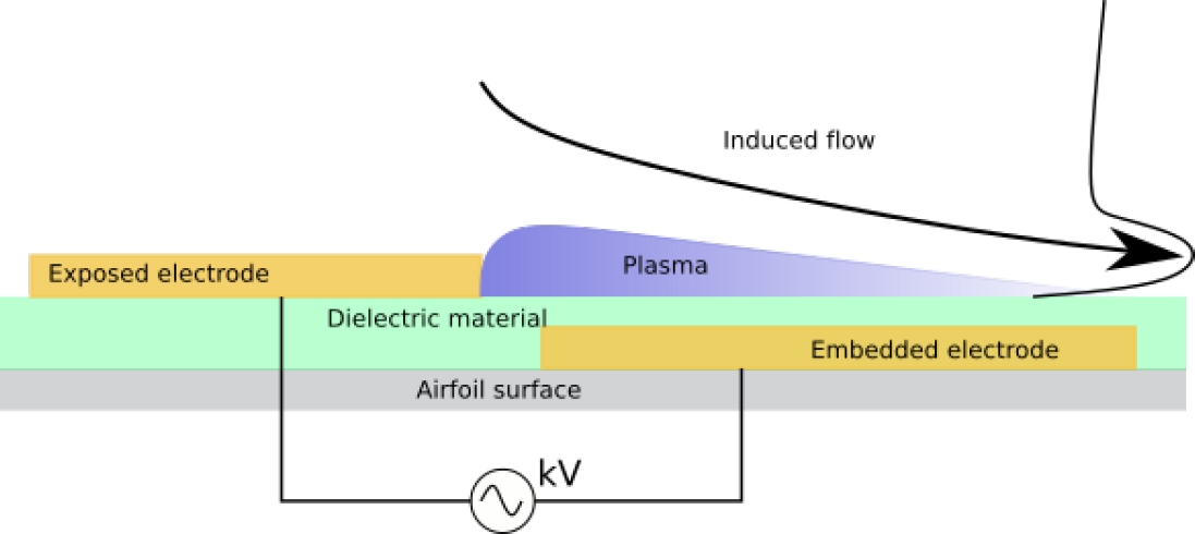
An SDBD actuator is a device that through an electrical discharge ionizes the air and by the acceleration of the ions by the electromagnetic forces there is a transfer of momentum inside the boundary layer which induces a jet inside the boundary layer, as seen in schematic diagram of Fig. 1, this causes a decrease and delay of the flow separation.

Fig. 1 SDBD scheme 

To simulate the propulsive force from the actuator, several computational models that seeks to accurately reproduce the properties of plasma, such as ion formation rate, and particle collisions. These models entails an increase in the computational cost making them unpractical for engineering applications.

The other type has an engineering focus such as the Suzen model [15] or Shyy model [14], these are based on the principle that the body force is directly proportional to the product of the charge density by the electric field.

However, these models have some drawbacks such as the electrodes should be strictly modeled into the domain since the thickness and position of these are necessary for the equations that determine the electric field, in addition to adding electric equations to the solver.

To avoid that disadvantages Dörr and Kloker [4] have used a technique in which the body forces are modeled as source terms. Kloker states that a SDBD can be modeled as a body force parallel to the wall. In the work done by Sato [13] he used the Suzen model to calculate the magnitude of the force that is applied as a source term directly in the momentum equation.

Plasma actuators have two modes of operation, they can work in a continuous mode in which it is continually activated, or through pulses as in the so-called burst mode. It has been proved that an actuator operating in the burst mode is more energy efficient, than an actuator in the continuous mode. [16, 13, 1, 6].

2 Modeling of the Flow and the Actuator

2.1 Flow Modeling

The flow field around the plasma actuator an the airfoil is described by the Reynolds-averaged Navier–Stokes equations (RANS) equations. In this work consider the flow as incompressible, the change in temperature is neglected, as it is known most of the energy that the plasma actuator consumes is transformed into kinetic energy, this leads to the required equations are the continuity and momentum equations:

u¯jxj=0, (1)

u¯it+u¯ju¯ixj=1ρp¯xj+xj[(v+vt)u¯ixj]+fbρ, (2)

where p is the pressure, u the speed, ρ the density, v the kinematic viscosity, vt the eddy viscosity, and fb the body force from the actuator. Since to fully resolve the Navier-Stokes equations would require much time and computational resources, a turbulence model is required. In this work we used the kωSST model.

This model uses a kω formulation in the inner part of the boundary layer from the wall to the viscous sub-layer. This formulation changes the behavior to kϵ model in the free current, leading to the advantage of avoiding the problem of over sensitivity, of the kω model to the turbulence intensity in the free current.

It is a model capable of capturing separation. The kωSST model is a lineal model, in which the Reynolds stress are modeled by the Boussinesq hypothesis that is a linear relationship:

ρuiuj=2μtSi,j23ρkδij, (3)

where μt is the eddy viscosity, k the turbulence kinetic energy and Si,j the strain rate tensor. Then the transport of energy from the turbulence fluctuations is modeled through the eddy viscosity. It is a two-equations model, with one for turbulent kinetic energy equation (4), and one for specific dissipation equation (5):

kt+Ujkxj=τijuixjβωk+xj[(v+σk1vt)kxj], (4)

ωt+Ujωxj=γ1vtτijuixjβω2+xj[(v+σωvt)kxj]+2(1F1)σω21ωktxiωxi. (5)

The turbulent viscosity vt in the model kωSST is described by the equation (6):

vt=a1kmax(a1ω,b1F23S). (6)

2.2 Actuator Modeling

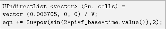
As mentioned in the previous subsection, the body forces provided by the plasma actuator are modeled by adding the source term, fb into the momentum equation (2).

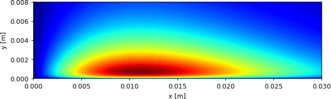
In this work we used the Kloker model [4] to obtain the the plasma extent over the wall, by using the equation (7), we obtained that the body force extends from the wall up to a distance of 0.003x/c, in the Fig. 2 the extension of body force is shown:

f(x,y)=cx[(a0a1x+a02a2x2)ea0x][(b1y+b2y2)eb0y2/5]. (7)

Fig. 2 Extension of the body force for an actuator 0.03x/c length 

Then the magnitude of the body force was selected from the results obtained by Hofkens [8] in which he determined the strength of a plasma actuator from velocity field data.

To obtain the unsteadiness of the body force, we multiply the body forces by the square of the sine function, as can be seen in the equation (8):

fb(x,y,t)=f(x,y)sin2(2πfbaset), (8)

where f is the force magnitude over the space, fbase is the base frequency, t is the time, and fb is the unsteady body force. This model is based on the assumption that the temporal variation of the body force can be characterized as push/push (Font [5]). As last step of modeling it is required to model the burst mode.

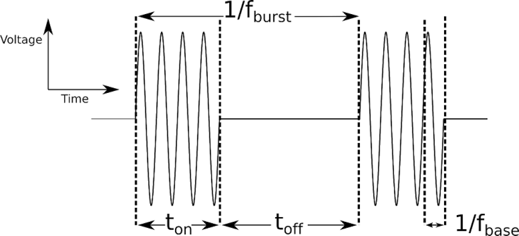
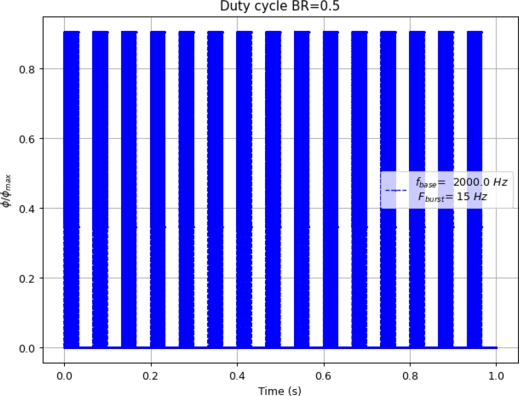
The burst mode is produced by a signal generated by the multiplication of low-frequency square signal with a high-frequency sinusoidal base signal, that way the actuation is periodically switched on and off. In Fig. 3 is shown a schematic of the burst mode, and in Fig. 4 a plot of the signal generated by a burst frequency of 15 Hz and a base frequency of 2 kHz is shown.

Fig. 3 Signal scheme for burst mode 

Fig. 4 Duty cycle for Fburst=15 Hz and fbase=2 kHz 

The burst mode is controlled by the burst ratio equation (9), and the burst frequency. If the burst ratio is equal to one (BR=1.0) the actuator is operating in the continuous mode. The burst actuation has the advantage for separation control, as some periodic excitation controls, the boundary layer receptivity, acoustic disturbances, coherent vortex shedding:

BR=tonton+toff=tonT. (9)

where the active time for each pulse ton is defined by equation (10) an the total time T of each pulse by equation (11):

ton=BRfburst, (10)

T=ton+toff=1fburst. (11)

The dimensionless base frequency f+=fbaseL/U and dimensionless burst F+=fburstL/U, where L is the length reference (airfoil chord) and U is the free stream velocity.

2.3 Computational Cases

The cases were divided in two setups in the first setup, the actuator was located at 3% (x/c=0.03) and 10% (x/c=0.01) of the chord length from the leading edge, then BR=1.0 and the fbase=2 kHz. In the second setup the actuator is placed at 3% (x/c=0.03) and it operates both in the continuous mode and in the burst mode, to clarify the control mechanisms of direct momentum addition. In the burst mode cases, the BR was set to 0.5 for all the burst mode cases, the burst frequency (fburst) was set to 3, 5 and 15 Hz, the base frequency (fbase) was set to 2 KHz for all the cases both in continuous and burst mode.

See Table 2 for the first setup, and Table 3 for the second setup of cases. The maximum force magnitude was 416N/m3 for all the cases, for comparison usually it is used the momentum coefficient (Cμ), this is defined by:

Cμ=BRFb,tot1/2U2L, (12)

where Fb,tot is calculated as

Fb,tot=00fbdxdy. (13)

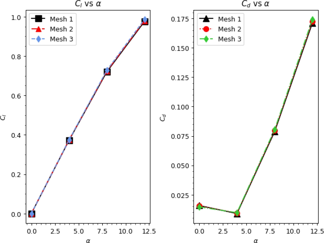
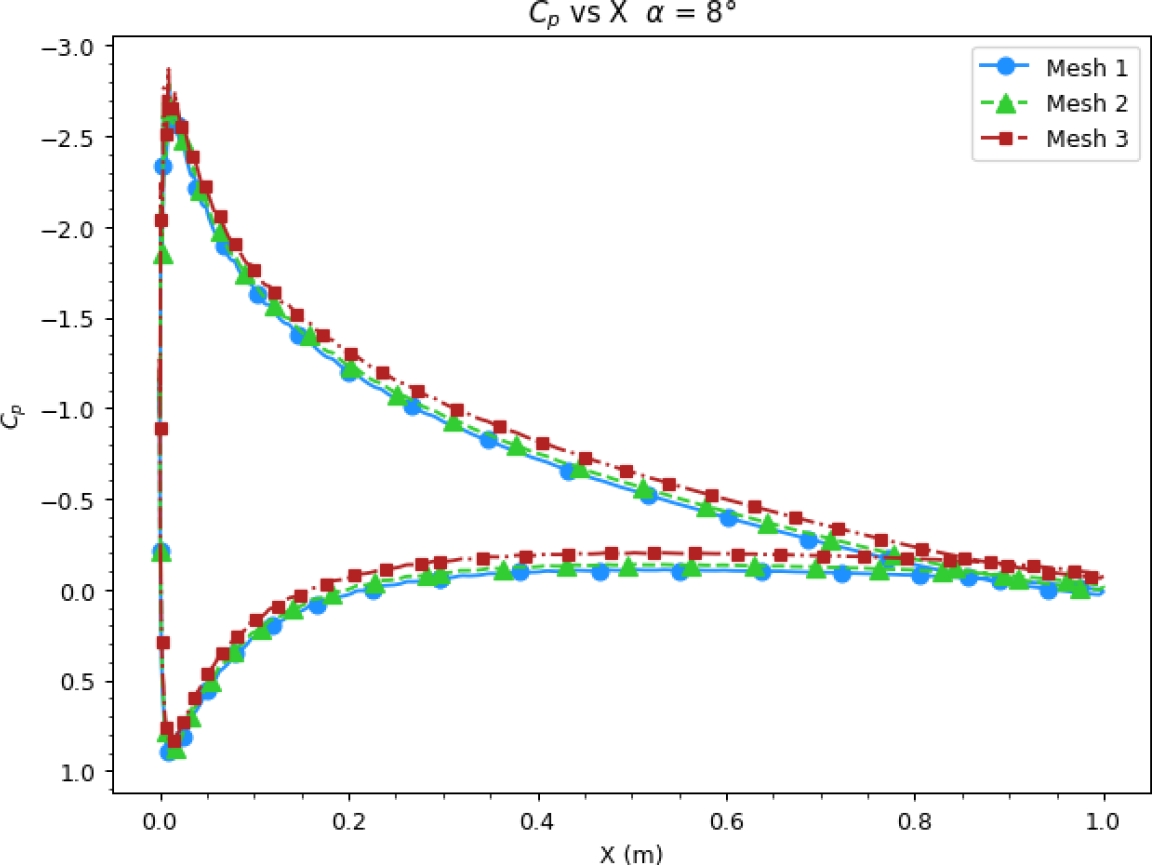
Table 1 Mesh properties 

Parameter Mesh 1 Mesh 2 Mesh 3
nodes 629,700 775,500 104,7340
cells 313,650 386,400 522,000
max aspect ratio 306.773 309.543 277.867
max non-orthogonality 29.171 29.5681 29.6446
max skewness 0.45114 0.45267 0.45037

Table 2 Cases for the study of the position of the actuator 

α° Position F+ fburst f+ fbase BR Cμ
0° - 16° 0.03x/c Continuous - 660 2.0 kHz 1.0 Cμ=2.89×10³
0° - 16° 0.10x/c Continuous - 660 2.0 kHz 1.0 Cμ=2.89×10³

Table 3 Cases for the study of the frequency of the actuator 

α° F+ fburst f+ fbase BR Cμ
16 1 3 Hz 660 2.0 kHz 0.5 Cμ=1.44×10³
16 5 15 Hz 660 2.0 kHz 0.5 Cμ=1.44×10³
16 15 45 Hz 660 2.0 kHz 0.5 Cμ=1.44×10³
16 Continuous - 660 2.0 1.0 Cμ=2.89×10³

This gives us a momentum coefficient Cμ=2.89×10³ for a BR=1.0, and Cμ=1.44×10³ for a BR=0.5.

3 Computational Setting Up

3.1 Numerical Grid

A structured C-type mesh was generated with the OpenFOAM utility
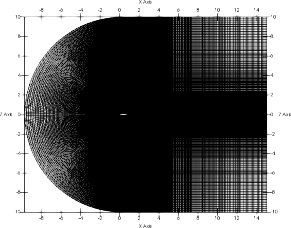
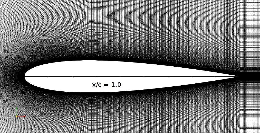
 blockMesh, Fig. 5 and Fig. 6 shows the mesh. The airfoil has a chord of 1.0=x/c, the mesh has a length of 25x/c and a height of 20x/c. Three meshes were used to perform a mesh independence analysis, the properties of each mesh are shown in the Table 1.

Fig. 5 General aspect of the mesh 

Fig. 6 Mesh detail 

The blockMesh utility generates parametric meshes with layering growth and curved edges. blockMesh works by breaking down the main geometry into a set of one or more three-dimensional hexahedral blocks. The mesh manifests as several cells in each direction of the block. Each block of the geometry is defined by eight vertices.

To use blockMesh a blockMeshDict file is needed, this file is in the case/system directory, this file contains the definition of the vertices, blocks, layering growth, block merging and boundaries.

To define the coordinates of the airfoil an .stl file with a 3D geometry of the airfoil was loaded into the blockMeshDict to define the airfoil coordinates in the mesh, this technique its easier than using the airfoil equation.

By executing the command blockMesh the mesh is generated, and the running status is printed in the terminal, any mistakes are picked up by blockMesh and the resulting error message appears in the command window. After the mesh the command checkMesh is executed to perform a mesh quality check. The mesh independence analysis was carried out, to ensure that the numerical solution obtained is independent of the number of nodes used.

Steady state simulations with same initial and boundary conditions were performed for a range of angles of attack from 0° to 12°. Through the comparison between the aerodynamic coefficients and the pressure distribution it was found that the solutions converge independently of the mesh, the mesh 3 was selected to carry out the study, the y+ was kept to y+5.

3.2 OpenFOAM Configuration

The simulations were carried out in the open-source software OpenFOAM. The actuator is simulated in OpenFOAM as force source term, that is added into the momentum equation. There are two ways of adding the force one involves modifying a solver and the other trough fvOptions.

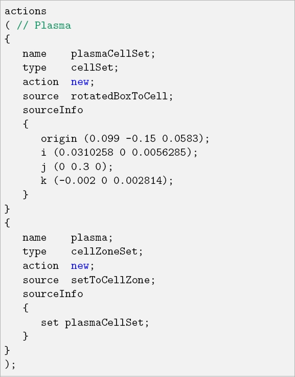
The body force can not be directly added by modifying a solver and adding the body terms in the momentum equation, since by doing this the body force will be applied to the whole domain as for example a gravitational force, as for this work is required that the force is applied only into a specific region, then we used the fvOptions application that allow us to apply an arbitrary source term into a set of specific cells (cell zone).

To generate the cell zone the topoSet utility was employed, this works with a dictionary system/topoSetDict.

In topoSetDict file the name of the region, its type, and source type are established. In this work the source was a rotatedBoxToCell which is a skewed, rotated box. Given as origin and three spanning vectors.

We used a rotated box because since the length of the actuator is small which allows the cell zone to adjust to the wall slope change along the airfoil chord. execute the function the command topoSet is used.

The actuator is simulated in OpenFOAM as force source term, that is generated with the CodedSource a fvOptions utility in which trough C++ language several types of source terms can be programmed. Once the arbitrary source term is programmed it will be acting on the selected cell zone.

A typical CodedSource file contains hook functions that allows the entry of sources through codeAddSup, restriction values before the equation is solved using codeSetValue and applying corrections after the equation was solved with codeCorrect. For this work inside the codeAddSup brackets the cell zone and time are called as follows:

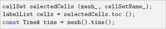
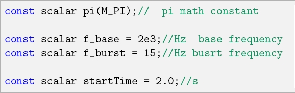
Then constants for the actuator frequency and strart time are defined:

After the force term is defined as a DimensionedField vector object with acceleration per volume dimensions, the magnitude is established and the term is added to the momentum equation:

For the boundary conditions, a condition of type fixedValue is applied to the entry to set the free current speed, a condition inletOutlet which provides a generic outlet when applying zero gradient for positive flows (outside the domain).

A boundary condition of type noSlip sets the speed with a value of zero. Also, in the airfoil wall functions are applied for turbulent kinetic energy kLowReWallFunction, turbulent viscosity nutkWallFunction and for the specific turbulent dissipation omegaWallFunction.

To ensure a two-dimensional flow, a boundary condition of type empty is applied to the boundaries perpendicular to the flow. The solver pimpleFoam was used, this solver uses the PIMPLE algorithm (merged PISO-SIMPLE ), to execute the PIMPLE solver in the so called PISO mode the keyword nOuterCorrectors must be 1 as follows:

The keyword nCorrectors indicates that the pressure poisson equation is being resolved twice so the pressure-momentum coupling is now stable enough to produce a non-diverging solution. The discretization schemes were a second order accurate and fully bounded setup to give precision and stability:

  • — time: backward,

  • — gradient: cellMDLimited Gauss linear 0.5,

  • — divergence: Gauss linearUpwind,

  • — laplacian: Gauss linear limited 1.0,

  • — interpolation: linear.

The linear solver was GAMG (geometric-algebraic multi-grid) for the symmetric matrix p, and for the asymmetric matrices U,k,omega and nuTilda a smoothSolver with GaussSeidel smoother.

The time step for the simulations was controlled by means of maximum Coruant number of 0.5, it was used and adaptable time step function to reduce the computation time for each simulation.

The simulations were solved in parallel on distributed processors. OpenFoam uses the public domain openMPI implementation of the standard message passing interface (MPI).

The decomposition method used was simple that is a geometric decomposition in which the domain is split into pieces by direction, in this work the domain was decomposed in 16 sub-domains.

4 Results

The simulations of a NACA 0015 airfoil were performed at Re of ×105 with the following initial conditions U=3.0m/s, ρ=1.0kg/m3 and v=1.5×5m2/s. To evaluate the effect of the position of the actuator along the chord over the lift coefficient Cl and drag coefficient Cd of a NACA 0015 airfoil were executed for a range of angles of attack from 0° to 16°, the actuator was placed at 3% (x/c=0.03) and 10% (x/c=0.1), the cases for this study correspond to the Table 2.

The Fig. 9 shows the velocity field when the actuator is inactive (off), and active (on). It is observed that when the actuator is inactive there is a flow separation zone that goes from the trailing edge to distance near 0.6x/c.

Fig. 7 Cl and Cd convergence 

Fig. 8 Cp convergence for a case at 8° 

Fig. 9 Velocity field at α=12°, actuator location x/c=0.03 

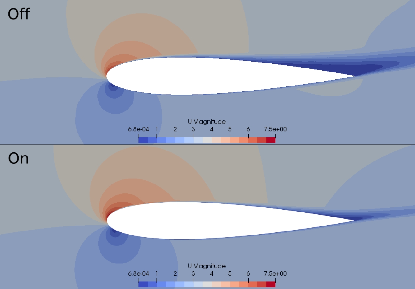
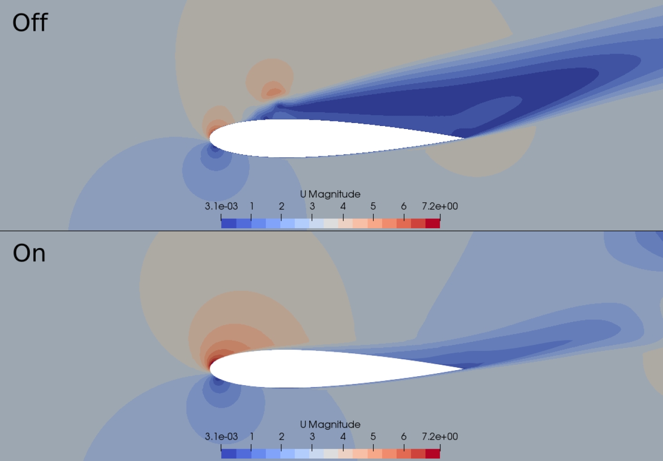
When the actuator is active the flow remains attached, the separation zone is reduced, its only appreciated near the trailing edge, in this case the actuator was placed at 0.03x/c. The flow reattachment its more visible when the airfoil is stalled as seen in the Fig. 10, in this case the actuator is able to take out the airfoil from the stall.

Fig. 10 Velocity field at α=16°, actuator location x/c=0.03 

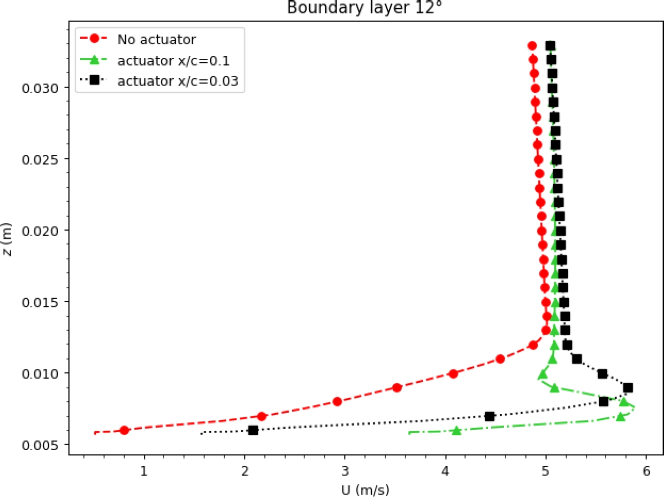
As mentioned in the section 1 plasma actuators add momentum to the flow, this induces a jet within the boundary layer, the simulations proved to be able to replicate the boundary layer jet as seen in Fig. 11. The Cp distribution for the cases on and off at the stalling angle α=16° are shown in the Fig. 12.

Fig. 11 Boundary layer measured at x/c=0.1 at α=12° 

Fig. 12 Cp distribution at α=16° 

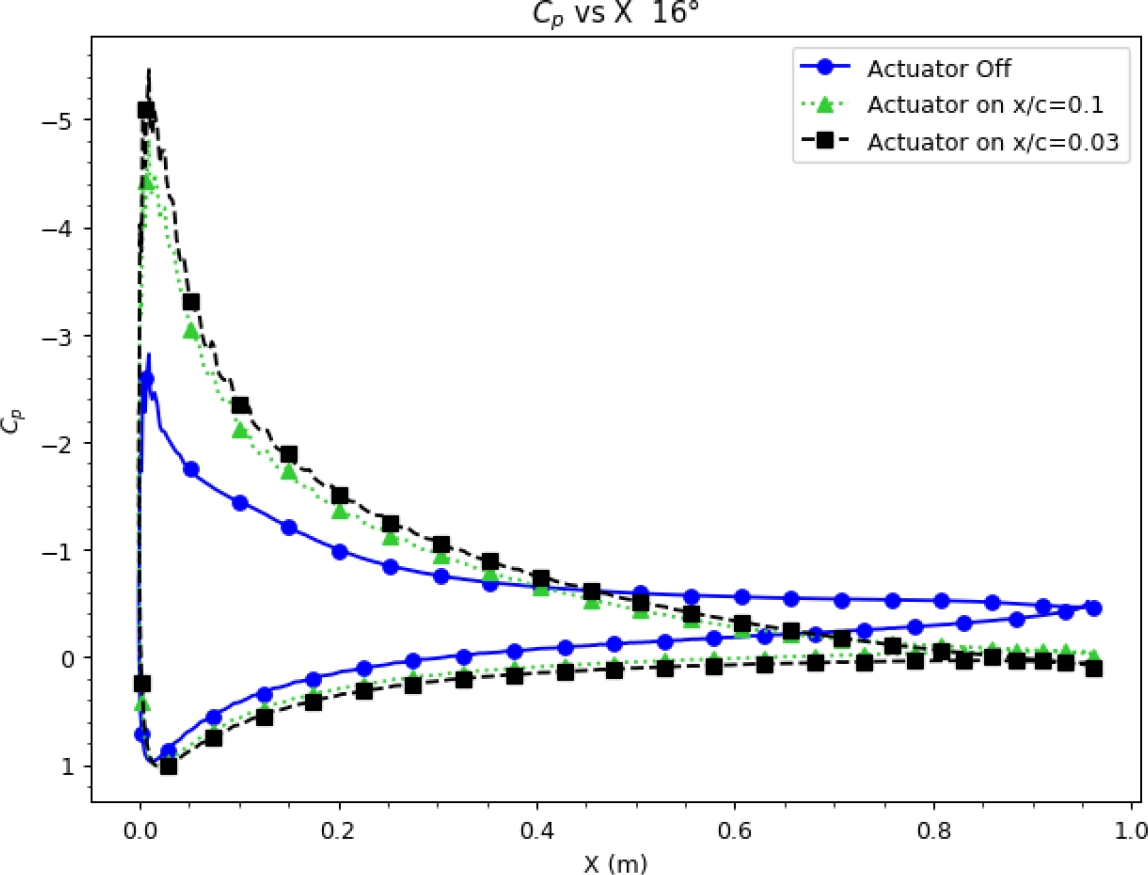
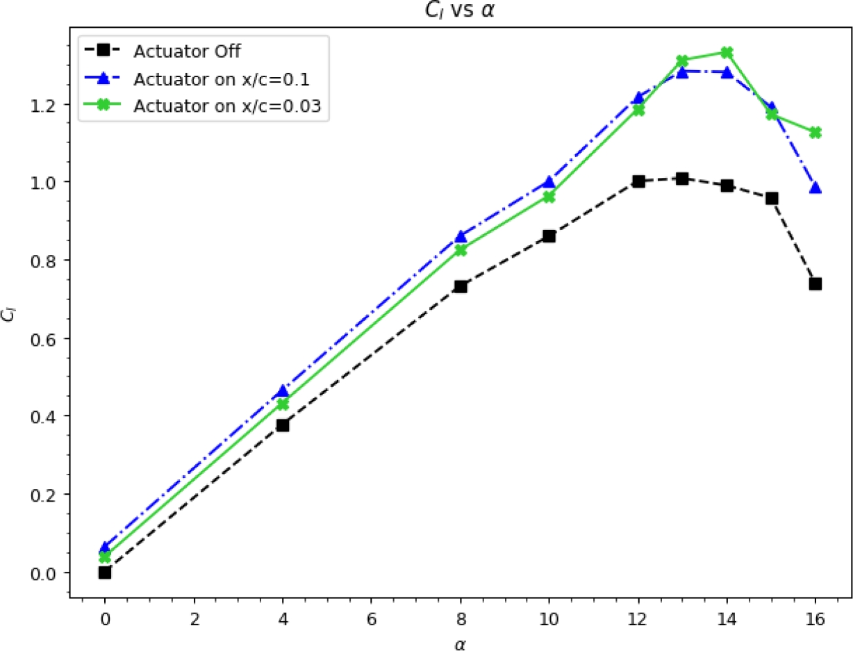
With the actuator off the pressure peak is almost vanished, and consequently the lift. When the actuator is on there is significant low pressure recovery near the trailing edge. Fig. 14 shows the enhancement of the airfoil as the Cl when the actuator is on is clearly higher compared to stall case with the actuator off.

Fig. 13 Comparison of the Cd versus angle of attack for Re=2.0×10⁵ 

Fig. 14 Comparison of the Cl versus angle of attack for Re=2.0×10⁵ 

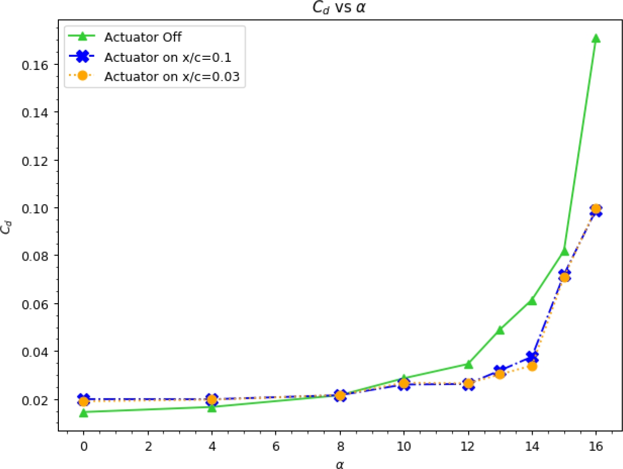
When the actuator is on there is a significant reduction of the drag at high angles of attack from a range from 12° to 16°, see Fig. 13, this reduction of the drag is due to the reattachment of the separate flow. To test the effect the burst mode, simulations were performed at 16°, the conditions of the actuator for each case are listed in the Table 3. In the Fig. 15 the Cl versus the time when the actuator is on.

Fig. 15 Cl versus actuation time, at α=16° 

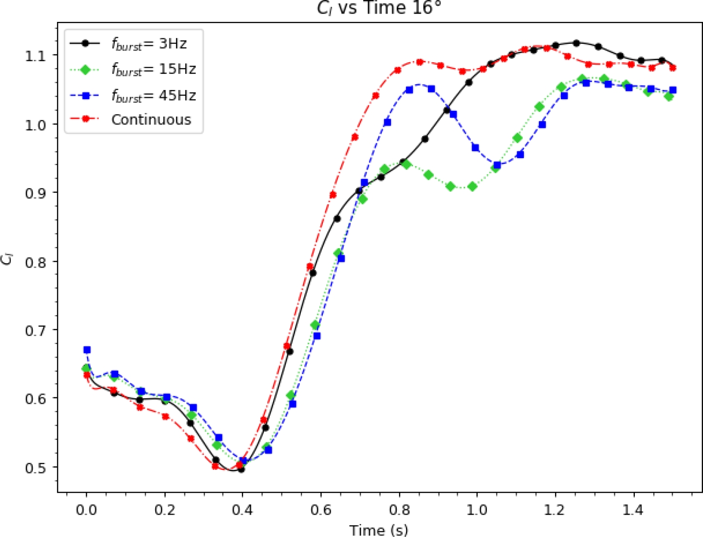
It is observed that independent of the burst ratio frequency the Cl have a behavior similar have a behavior similar to that of a step function, the main differences between them are the smoothness of the Cl increase evolution, and time to reach the maximum Cl. The highest Cl is for the continuous mode case (BR=1.0) and for the case with fburst=3 Hz (BR=0.5).

Fig. 17 shows the temporal evolution of the velocity in a half period (T=0.5), measured in a point 3 mm downwind the actuator and 1 mm over the wall, from this plot the effect of the burst mode as the actuator is being activated and deactivated, for example for a fburst=15 Hz it is possible to count 7.5 on and off states, since the graph only shows a half period.

Fig. 16 Simulation and experimental Cl validation plot 

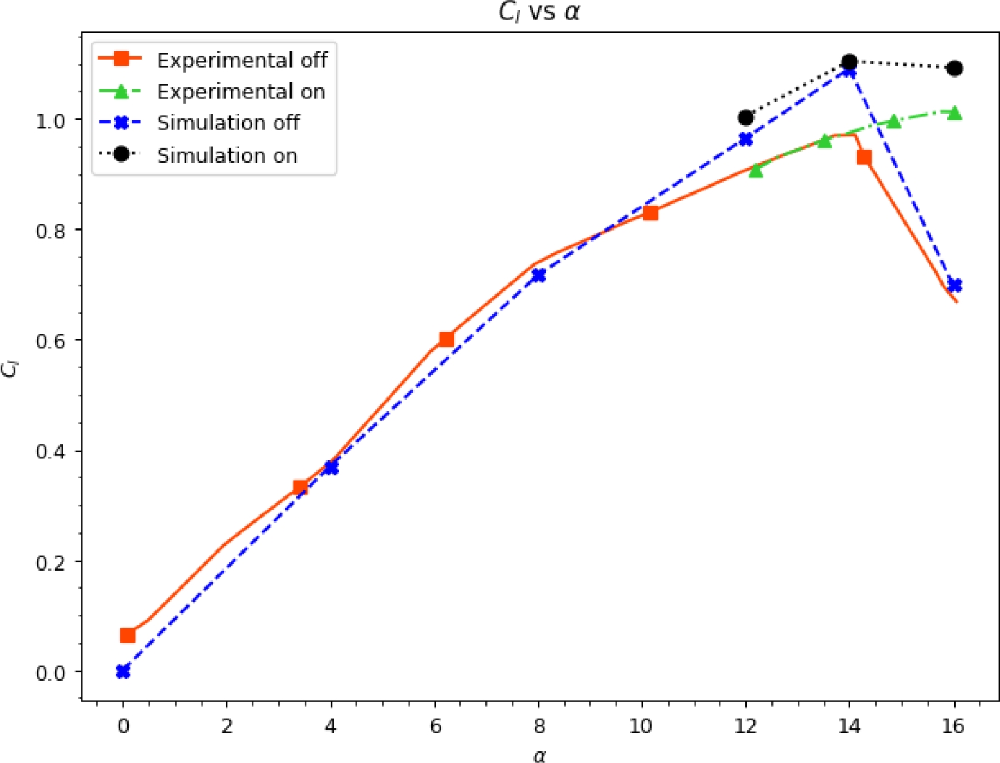
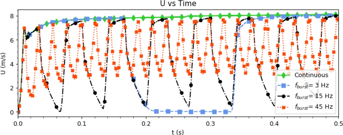
Fig. 17 Evolution of the velocity in a point at x= 3 mm downwind the actuator and z=1 mm over the wall, fbase=2 kHz 

4.1 Validation

To validate the technique implemented in this work, were performed at a Re of 1.58×10⁵ to match the Re used by Post in his experiments, and compare the Cl and Cp from the simulation with the data reported by Post [12]. In Fig. 16 the Cl polar shows the experimental data from Post and the simulations.

It is observed that the simulations Cl has similar behaviour than the one from the experiments, when closer to the αmaxCl the Cl tends to be overestimated. This may be caused by the use of RANS turbulence model, it may be possible to get a closer approximation with a more precise turbulence model as Large Eddy Simulation (LES) models and with an smaller time step.

5 Conclusion and Future Work

The results of the CFD analysis technique applied to an airfoil section showed us a great potential and high capabilities to simulate and evaluate the Kloker plasma-fluid model for a Single Dielectric-Barrier Discharge and the kωSST turbulence flow model during the coupled.

This technique is cheap, fast, effective and free of the software licenses to simulate the performance of any plasma solver to attach the boundary layer after the stall or bubble separation in a wing section.

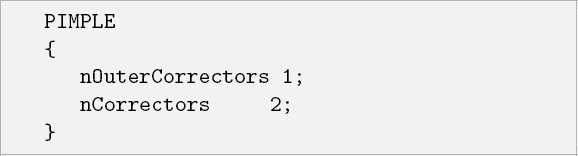
The numerical algorithm called pimpleFoam with nCorrector is one of the most stable setups for this case and the accuracy of the results strongly depends on the choice of grid size, y-plus, wall function and discretization scheme.

The tested cases showed that when the actuator its closer to the separation region produces a higher increase of the Cl and a larger reduction of the separation zone, as a matter of fact if the separation occurs at 0.5x/c the actuator placed at 0.1x/c generates a Cl increase slightly higher than the one from the actuator at 0.03x/c, keeping in mind than the separation depends on the angle of attack.

Plasma actuator has great advantages, such as responsivity, low weight, a simple structure, and a low energy consumption.

Reason enough, for this paper who provides detailed data support for subsequent numerical and experimental studies on airfoil cases with a 3D flow and more complex turbulence models.

References

1. Aono, H., Sekimoto, S., Sato, M., Yakeno, A., Nonomura, T., Fujii, K. (2015). Computational and experimental analysis of flow structures induced by a plasma actuator with burst modulations in quiescent air. Mechanical Engineering Journal, Vol. 2, No. 4, pp. 15–233. DOI: 10.1299/mej.15-00233. [ Links ]

2. Bernal Orozco, R. A., Arias-Montano, A., Huerta, O. (2020). Separated-flow control simulation with a periodic excitation by sdbd plasma actuator at re=o(20_5). Journal of Aerospace Engineering, Vol. 33. DOI: 10.1061/(ASCE)AS.1943-5525.0001185. [ Links ]

3. Corke, T., Post, M. (2005). Overview of plasma flow control: concepts, optimization, and applications. 43rd AIAA Aerospace Sciences Meeting and Exhibit, pp. 563. DOI: 10.2514/6.2005-563. [ Links ]

4. Dörr, P., Kloker, M. (2015). Numerical investigation of plasma-actuator force-term estimations from flow experiments. Journal of Physics D: Applied Physics, Vol. 48, No. 39. [ Links ]

5. Font, G., Enloe, C., McLaughlin, T. (2010). Plasma volumetric effects on the force production of a plasma actuator. AIAA Journal, Vol. 48, No. 9, pp. 1869–1874. DOI: 10.2514/1.J050003. [ Links ]

6. Fujii, K. (2014). High-performance computing-based exploration of flow control with micro devices. Philosophical Transactions of the Royal Society A, Vol. 372, No. 2022. DOI: 10.1098/rsta.2013.0326. [ Links ]

7. Greenblatt, D., Müller-Vahl, H., Lautman, R., Ben-Harav, A., Eshel, B. (2015). Dielectric barrier discharge plasma flow control on a vertical axis wind turbine. Active Flow and Combustion Control. Springer, Vol. 127, pp. 71–86. DOI: 10.1007/978-3-319-11967-0_5. [ Links ]

8. Hofkens, A. (2016). Determination of the body force generated by a plasma actuator through numerical optimization. Master’s thesis. [ Links ]

9. Huang, J., Corke, T. C., Thomas, F. O. (2006). Unsteady plasma actuators for separation control of low-pressure turbine blades. AIAA Journal, Vol. 44, No. 7, pp. 1477–1487. [ Links ]

10. Joslin, R. D., Miller, D. N., Lu, F. K. (2000). Fundamentals and applications of modern flow control. American Institute of Aeronautics and Astronautics. [ Links ]

11. Kumar, V., Alvi, F. S. (2006). Use of high-speed microjets for active separation control in diffusers. AIAA Journal, Vol. 44, No. 2, pp. 273–281. DOI: 10.2514/1.8552. [ Links ]

12. Post, M., Corke, T. (2004). Separation control using plasma actuators-stationary & oscillating airfoils. 42nd AIAA Aerospace Sciences Meeting and Exhibit, American Institute of Aeronautics and Astronautics, pp. 841. DOI: 10.2514/6.2004-841. [ Links ]

13. Sato, M., Nonomura, T., Okada, K., Asada, K., Aono, H., Yakeno, A., Abe, Y., Fujii, K. (2015). Mechanisms for laminar separated-flow control using dielectric-barrier-discharge plasma actuator at low reynolds number. Physics of Fluids, Vol. 27, No. 11. [ Links ]

14. Shyy, W., Jayaraman, B., Andersson, A. (2002). Modeling of glow discharge-induced fluid dynamics. Journal of Applied Physics, Vol. 92, No. 11, pp. 6434–6443. DOI: 10.1063/1.1515103. [ Links ]

15. Suzen, Y., Huang, G., Jacob, J., Ashpis, D. (2005). Numerical simulations of plasma based flow control applications. AIAA Paper, Vol. 4633. DOI: 10.2514/6.2005-4633. [ Links ]

16. West, T., Hosder, S. (2012). Numerical investigation of plasma actuator configurations for flow separation control at multiple angles of attack. 6th AIAA Flow Control Conference, pp. 3053. DOI: 10.2514/6.2012-3053. [ Links ]

Received: June 08, 2020; Accepted: December 20, 2021

* Corresponding author: Oliver Marcel Huerta Chávez, e-mail: lecram_21@hotmail.com

Creative Commons License This is an open-access article distributed under the terms of the Creative Commons Attribution License