


 nueva página del texto (beta)
 Inglés (pdf)
 Artículo en XML
 Referencias del artículo
 Enviar artículo por email
 Citado por SciELO
  Similares en
SciELO
Similares en
SciELO 
 Permalink
1 Introduction
The inception of network-on-chip (NOC) has created a new paradigm for on-chip communications. The major reasons for this acceptability are its high scalability, better latency, high throughput and less area consumption [1].
However, each of these factors have a large dimension for improvement and research. Among all the topologies designed for NOC, the mesh topology has gained a lot of attention. The popularity was because it could accommodate a good number of clients and also for its seamless scalable property.
Besides, as every switch had at least one path to every other switch the routing was quite simple and easy to simulate. But later researches showed that with the increase in network size, there was a high probability for packet loss [17, 15, 8, 20].
Also, as every switch had only one client connected to it, scalability often resulted into performance degradation [16, 4]. In order to conceal these issues, the routing was improved to a larger extent, but still it always had some loophole due to which an alternative was of utmost need. In 1985, Charles E. Leiserson proposed the Fat-Tree topology which is more like a real tree [18].
Unlike the conventional trees used in computer science, the link size of the Fat-Tree gets thicker as one traverse from leaves towards the root. Charles E. Leiserson in [18] has proved the universality of the Fat-Tree network by offline simulation that for any network size, Fat-Tree gives the best routing and efficient utilization of hardware. Network-on-chip being a real time scenario, the parallel computation has always been an important factor.
Implementing the Fat-Tree for network on a chip has proved to be a major achievement in addressing issues like scalability, high performance, modular design etc. A. Bouhraoua et al. [14, 10, 9, 11, 12] restructured the Fat-Tree proposed by Leiserson into more efficient one by including new downlinks that could rectify the contentions of the conventional Fat-Tree.
But, this version had more number of links at the bottom level switches due to which additional chip area is required to accommodate all the extra wirings. Hence, as the topology grew, the size of buffers also increased, consuming a large area of the chip. They also presented a heterogeneous architecture [13] of their modified Fat-Tree where the downlinks were of different bandwidths. These architecture was designed to meet the real time scenario of communication where the clients may have different individual bandwidths.
This architecture reduced the wastage of bandwidths and enabled the clients to receive packets through multiple options. For optimal utilization, the packets were broken to smaller segments called flits. However, this only resulted into requirement of a large number of buffers to store these flits. Another improved version of the Fat-Tree was presented by Gomez et al. named as Reduced Unidirectional Fat-Tree (RUFT) with non-minimal routing [23]. This routing scheme forced the packets to travel till the last stage of the network prior to travelling downwards towards the clients. As a result, even if the communication was to be made between adjacent clients, the packet had to travel an unnecessary distance till the last stage resulting unwanted delay.
In this paper, we have presented a further improved version of the Fat-Tree which addresses the previous issues of Bouhraoua and Gomez. Our proposed architecture uses buffer in the form of hierarchical ports to store the flits of a packet to implement flit wise communication. Further, in order to minimize the hardware used to realize the network, new links have been introduced between the switches which connects these clients. With these architectural changes and improvised routing, the proposed Fat-Tree is simulated to see the route ability of the network.
2 Related Work
Out of the various dimensions for research in network-on-chip, topological challenges and routing has taken the centre stage. The topology deals with how to make NOC compatible with the area of the chip by carefully placing the IP cores(Intellectual properties) along with network nodes(routers or switches), the routing deals with ways to gain better performance and throughput with minimum latency and packet loss by carefully choosing the path from source to destination in any given topology. Combined together, the topology and routing makes an architecture.
Guerrier et al. [16] presented an architectural overview of scalable interconnections where they also illustrated how the shared bus architecture would fail to meet the requirements of future interconnections. They proposed a state-of-art for a packet switched interconnection with wormhole routing for better performance. However, during analysis it was seen that there was an increase in the latency with the network load, resulting in performance degradation which was not acceptable. Couple of years later, Shashi Kumar et al. [17] came up with a m x n mesh network where every switch was connected to four other adjacent switch providing better interconnection. But, even this network failed to take network load beyond 50% due to packet loss and latency.
In order to meet the synchronization on the chip, Sheibanyrad et al. [24] came up with a globally synchronous and locally asynchronous (GALS) network using hybrid FIFOs. These FIFOs were used for maximizing throughput and minimizing the probability of metastability. Although there was a large latency, yet the model achieved high throughput. A topology adaptive network was proposed by Bartic et al. [3] which provided scalability and flexibility to choose both network as well as the routing. Based on virtual cut through switching, this design could lower the latency to a good extent.
Relevant to our proposed work, Bouhraoua et al. [14, 10, 9, 11, 12] have made significantly contributed in restructuring the conventional Fat-Tree network. The original Fat-Tree designed by Leiserson had contentions in the downward links.
The Fat-Tree structure proposed by Bouhraoua et al. [14] doubled the downward links of the original Fat-Tree resulting increase in the number of links from top to bottom. In order to store the large number of packets at the lowest levels, additional FIFOs were introduced. Though this modified Fat-Tree rectified the contentions of the original tree, but due to FIFOs, a large amount of chip area had to be consumed. The large number of downlinks increases the bandwidth, but in real time, only few of this bandwidth was actually used. In order to meet this wastage, Bouhraoua et al. [11] introduced heterogeneous bandwidth in the downlinks and also broke the packets into smalle segments.
Although, this reduced the wastage of bandwidth but also resulted into increase in the FIFOs and hence the constraint on area still prevailed. Later, Bouhraoua et al. [12] improvised their earlier design of modified Fat-Tree along with new routing strategy based on clusters. But hardware utilized remained unchanged. They simulated the network for uniform and non-uniform addresses.
Although, the average latency increased but the network did not reach any saturation level which prevailed in earlier designs. In contrast to mesh topology which saturated at 30% injection rate, their improved modified Fat-Tree did not saturate till 90% injection rate.
But, with their routing strategy, there was always an unwanted delay even when the adjacent client communicated with each other. Similar issue was found in the RUFT network proposed by Gomez et al. [23]. The network defined by them had unidirectional multistage interconnections which rectified the downwards contentions of the original Fat-Tree. But, due to non-minimal routing, each packet has to reach the last stage of the network before moving downwards unlike in [12], where the downward path is available from a level of router which are called summit, which may or may not be the highest level of router in the Fat-Tree topology.
In [21], an extended zoned node is presented which promotes the usage of extra links with an aim to create connected layers and to increase the bisection bandwidth of the network and to provide fault tolerance. The extended zoned nodes does not minimize the hardware used rather is deployed to make super nodes to cater the needs of high throughput and minimized latency.
In [2], a SMBFT is proposed, which minimizes the hardware used in a BFT and has proven to be efficient but at the cost of complicating the router design by adding multiple extra links per router as opposed to the proposed work which only added a single lateral link per router in the network.
A partial group based routing for the modified Fat-Tree was presented by Biswas et al. [7] where the routing did not necessarily travel the last level of the network prior to traveling downwards till the destination clients.
In their work they partitioned the complete network into two equal groups and for reaching the destination client the packets only had to travel to the highest level if the destination client was in a different group. This new routing strategy addressed the unwanted delay which was a major disadvantage in Bouhraoua et al. [14, 10, 9, 11, 12] and Gomez et al. [23].
When compared with the original Fat-Tree, the routing approach of Biswas et al. [7] could reduce the routing activities from 8% to 13%. Later a fully grouped routing strategy appeared in [5] where Biswas et al. extended the number of groups from 2 to network dependent. This means, as the network size increased, the number of groups increased too.
Both these routing strategies in [7] and [5], homogeneous modified Fat-Tree was implemented. Both reduced the unwanted delay for adjacent clients to communicate but it was not eliminated as the packets still had to travel at least to a next higher level before traveling downwards till the destination client.
In an attempt to address all these issues in the modified Fat-Tree, we in the coming section present our proposed Reduced Switch Scalable MIN Fat-Tree topology. For better understanding of the proposed topology next section describes the MIN Fat-Tree and Partial group based routing in homogeneous Fat-Tree topology.
3 Fat-Tree Topology
A generalized definition of Fat-Tree states that [22, 25] a Fat-Tree is a collection of vertices connected by edges and is defined recursively as:
(i) A single vertex by itself is a Fat-Tree. This vertex is also the root of the Fat-Tree.
(ii) If
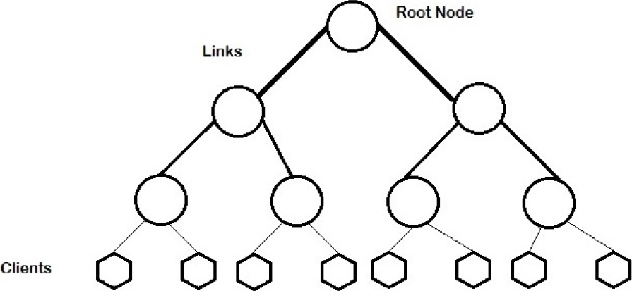
The above definition is very general and covers almost all trees in text. A general Fat-tree as proposed by Leiserson and described above is depicted in Figure 1. Notice that in Figure 2, the links from the lower levels getting thicker and thicker as we climb up in the hierarchy. Due the limitation of a single root Fat-Tree, the attention from this type of network has shifted to another class of Fat-Trees called k-ary n-trees. The general k-ary n-trees have been borrowed from another popular multistage interconnection networks known as k-ary n-fly or popularly known under the text as butterfly networks [5, 6]

3.1 Routing in Fat-Tree topology
As described by Bouhraoua and Elrabba in [14, 10, 9, 11, 12], the Fat-Tree in the above figure 1(b) is characterized the routing of the packets from source to destination which is similar to a binary tree. The packet from the source is routed in the upwards direction until a router is reached which has the downward connection to the destination. This router is termed as “routing summit”.
An n row network has
The address of the clients is in the interval [0,
The reach range of a router is defined as the number of client addresses it can reach. The network architecture dictates that the reach range of a router (r,c) is divided into two intervals
A group here is defined as the lower level routers to which a upper level router (r,c) is connected to. The lower level router connected by the left link of the router (r,c) is called the left group
3.2 Partial Group Based Routing for Homogeneous Fat-Tree Topology
A Partial Group Based Routing Algorithm is described here for the MIN Fat-Tree topology [7]. For the sake of scalability the original MIN Fat-Tree structure of Figure 1(b) shown above has not been changed. The routing for the original MIN Fat-Tree presented in [14] is based on the calculation of right and left intervals in every router whenever a packet is received by it for routing decisions. The calculation of the right and left interval is explained above.
The partial group based routing is an attempt of reducing the calculation of these intervals by routers for only half of the time in each direction of the packet flow. This objective is achieved by logically grouping the entire MIN Fat-Tree into two halves. Each half of the topology will contain routers and clients. The topmost routers of the topology do not belong to any group and serve to identify the proper group of a destination client while routing decision takes place.
The routing is designed such that, the original routing of the Fat-Tree remains the same while routing in the same group. Whenever an intergroup routing decision is to be taken the partial group based routing kick starts. The figure below shows the logical grouping of an eight client MIN Fat-Tree topology.
The figure above shows that any MIN Fat-Tree network of n clients will be divided dynamically into two groups with each group having
Whenever a source sends a message from one group to the another, the packets are straight forwardly routed to the topmost level where depending upon the group id of the destination client the packet is sent downwards either by the right link or the left link of the topmost router.
The general convention of binary tree is followed where, if the destination group id is smaller than the source group id, the packet is forwarded via the left link of the topmost routers otherwise the packet is forwarded by the right link of then topmost routers. Assigning group id dynamically is straight forward and given by:
where c is the client such that 0≤c≤n-1.
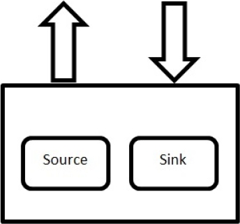
For the simulation purpose, a logical router is designed having four hierarchical ports fully connected to each other using bidirectional links. The port is the place within the router where the routing decision takes place. A port within the router contains three parts, a Scheduler, an Inport, and an Opcal. The router structure and a port structure are depicted below for better understanding.
The group id of the router is given such that, any router with in column 0 to
The scheduler in the port determines whether the packet is destined for a client contained within the group as the router is in, if so, the packet is forwarded to opcal via Inport.
Opcal is the place where routing decision is taken in the port and the packet is routed according to the original routing algorithm of MIN Fat-Tree described in [9], where the left and right range of the router is determined by
If, the packet injected from the source to the router is not destined to any client in the group formed by equation (1), then the scheduler forwards the packet to the higher levels of the topology. The packet eventually reaches the topmost group from where the downward path of the packet starts.
Note here that, the range calculation and routing decision is taking place only in the routers which belong to the same group as the destination client otherwise the packet is forwarded upward until the topmost routers are reached, which as mentioned earlier serves as group identifiers.
The Inport module in the router serves to distinguish, packets from scheduler and opcal. A packet received from scheduler by Inport signifies that the routing decision for the packet has to be made and the packet is forwarded to the opcal, while a packet from an opcal received by the Inport signifies that the routing decision has already been taken and the packet is forwarded to the scheduler. The figure below shows a logical client and router interface.
The results thus collected from the simulation of above networks are presented in section 5 along with the results of the proposed topology for comparative analysis. The next section describes the proposed reduced switch scalable min Fat-Tree topology.
4 Proposed Work: The Reduced Switch Scalable MIN Fat-Tree Topology
In this section we first explain the structure of the individual modules of the switch scalable MIN Fat-Tree. Thereafter a detailed explanation of the improved topology along with routing has been formulated.
4.1 Modules of the Proposed Network
The primary modules for a network are the routers, the clients and the interconnection links. The routers for the improved Fat-Tree network consists of hierarchical ports which are connected to each other. The interconnections among the ports have been so designed that two types of communications are possible, port-port and router-router. The port-port connection enables communication of message flits within the router. This would enable the flits to travel in the distinct links after the routing decision has been made by the router.
Due to hierarchical connections, alternative paths can be chosen whenever, the desired link is busy. Once the port-port communication is over, the flits travels out of the respective router towards the destination client or to other routers in the path. The ports have schedulers incorporated within them for taking the routing decisions. Whenever, the header flit of the message arrives at the port for the first time, the scheduler computes the routing and redirects towards to the respective port towards destination. The entire routing has been explained in the subsequent section.
Similar to the original Fat-Tree, our reduced switch scalable MIN Fat-Tree has all the clients connected to the lowest routers. Each router at the last level has two clients connected to them. Each of the clients has a source and a sink to generate and receive messages. An unique identification number has been assigned to each clients which has been used as destination address for communication.
4.2 The Reduced Switch Scalable MIN Fat-Tree Topology
The topology of new Reduced Switch Scalable MIN Fat-Tree is proposed here which not only reduces the hardware switches but also is implicitly scalable to number of client N, where N
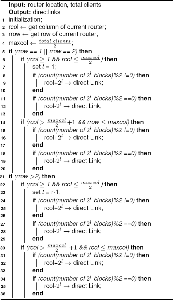
The reduced switch scalable MIN Fat-Tree will have direct links between the routers according to the height of the tree with at least 8 clients. Each router will have only one direct link attached to consecutive router. A tree with m clients can be represented as m=
Here, (r,c) is the level and column index of each router. The factor of 2 is added or subtracted to the column index shown in equation (2) whenever an odd number or even number of
4.3 Proposed Routing
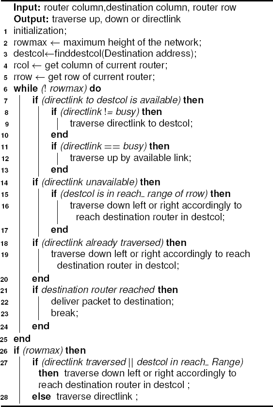
The proposed routing for reduced switch scalable MIN Fat-Tree is based on Wormhole Routing [19]. The message packet has been divided into a number of flits (flow control digits) for transmission. Generally, the bits constituting a flit are transmitted in parallel between any two routers. The header flit (or flits) of a packet directs the route. As the header flit advances in a specified route, the remaining flits follow in a pipeline fashion. If the header flit encountered a channel busy, it is blocked until the channel becomes available. These flits remain in flit buffers along the established route. Once a channel has been acquired by a packet, it is reserved for the packet. The channel is released when the last, or tail flit has been transmitted on the channel.
For ease of anticipation, prior to routing algorithm, we first present an example to demonstrate how the message packet traverses in the improved Fat-Tree. Let us consider an 8 clients network as shown in Fig. 5.


Let the routers be numbered from 1-4 in the lowest level and 5-8 in the highest level of the network. The new links introduced are between routers 1 & 3, 2 & 4, 5 & 7 and 6 & 8. Hence, if a message packet needs to travel from a client in router 1 to destination in router 3, it has two links of the conventional Fat-Tree to travel to upper level and a new direct link between routers 1 & 3. Since, the network has been evenly partitioned into two equal partitions (routers 1, 2, 5 & 6 in first part and so on) it turns quite simple to take a routing decision. Whenever the header flit arrives router 1, the routing first fetches the destination address and checks whether it belongs to the same partition or different one.
If the partition is same, it could use the conventional Fat-Tree routing but if the destination is in different partition then first it will forward the packet with those new links of the improved Fat-Tree so that they directly reach the router to which the destination clients are connected. Only if these links are busy then they would follow the path to upper level and take similar routing decisions in those upper level routers.
The topology of the proposed network is free from deadlocks but, is prone to live locks. Here, the routing algorithm is designed so that it avoids livelocks by restricting the movement of flits in the upper part of the network once it has traversed the lateral links i.e. once a packet has traversed the lateral link, it can only be routed in downward direction.
Before presenting the proposed routing technique, we first present some preliminaries for easy anticipation. As each router at the lowest level have two clients connected to them, hence from if the total number of clients are known, the number of columns in the network can be computed by:
The network defines the location of each routing switch with its position in the row and column, which can be fetched through a simple operation. However, the client addressing has been done by just assigning a positive integer n, where n ∈ {1, 2, 3......} in such a way that all the odd number will represent the left client and vice versa. At any instance to fetch the details of the client a function finddestcol( ) is called to within routing such that:
The routing is primarily focused on three situations, (a) if destination is at the two ends of the network (b) if destination is in the centre of the network and (c) anywhere other than (a) and (b). If the destination client is at either end of the network, then the routing first targets to identify the direct links between the routers, if any exists. If they do, then the messages are directly forwarded by them. Else, they are sent a level up and again direct links are being searched and forwarded if found.
If only no such links exists or these links are busy then the messages are forwarded by conventional Fat-Tree routing till they reach the destination column. Once the packet is in the destination column, the destination is reached by forwarding the packet downwards by the rightmost links of each successive router in the downward path to the client.
Another important aspect of the routing is the level at which the messages reach. As the message travels to the next higher level, the direct links traverse the message to a router by a factor
5 Results and Discussion
The simulation of the topologies mentioned in previous sections are done by using a data packet of 4 bytes for all the topologies and a generation function of injecting one packet per cycle is utilized. The time period of a cycle is fixed for 2ns.
The OMNeT++ environment is installed in Windows 10 operating system. Two destination address generation schemes are utilized, one is a uniform address generation scheme which uses the intuniform() library function present in OMNeT++ header file.
This function generates a uniform destination address for the entire list of client present in the system.
For another type of destination address generation, a static address is chosen, which always forwards a packet from all the clients to a particular client, there by modeling the worst case performance of the topologies.
5.1 Message Generation
The message has been generated at the source of the client module in the network. Every single message is broken up into flits in such a way that the header flit hops into router for routing decision and all other follows till destination is reached. Buffers are used in the form of ports. The destination address in the packet decides the amount of traffic in the network during one simulation. Two different kinds of destination address generation techniques have been taken into consideration. The function used is:
where x and y are have values such that x + y < total number of clients in the network. The function generates random destination address by adding any value from the range 1 to y with x. This method implies that the clients were placed without any consideration of their communication patterns. The uniform generation is good as it will stress out the network as it will cause more packet hops.
5.2 Network Analysis
In order to analyze the proposed reduced switch MIN Fat-Tree network, two parameters have been considered. The latency measures the delay in delivery of a message generated from a source. The hop count measures the number of hops the message had to make from source to destination. The network has been simulated for 8, 16, 32, 64 and 128 clients along with same number of clients for MIN Fat-Tree and with 64 clients of Partially Grouped MIN Fat-Tree. The results have been shown below.
5.2.1 Latency and Hop Count
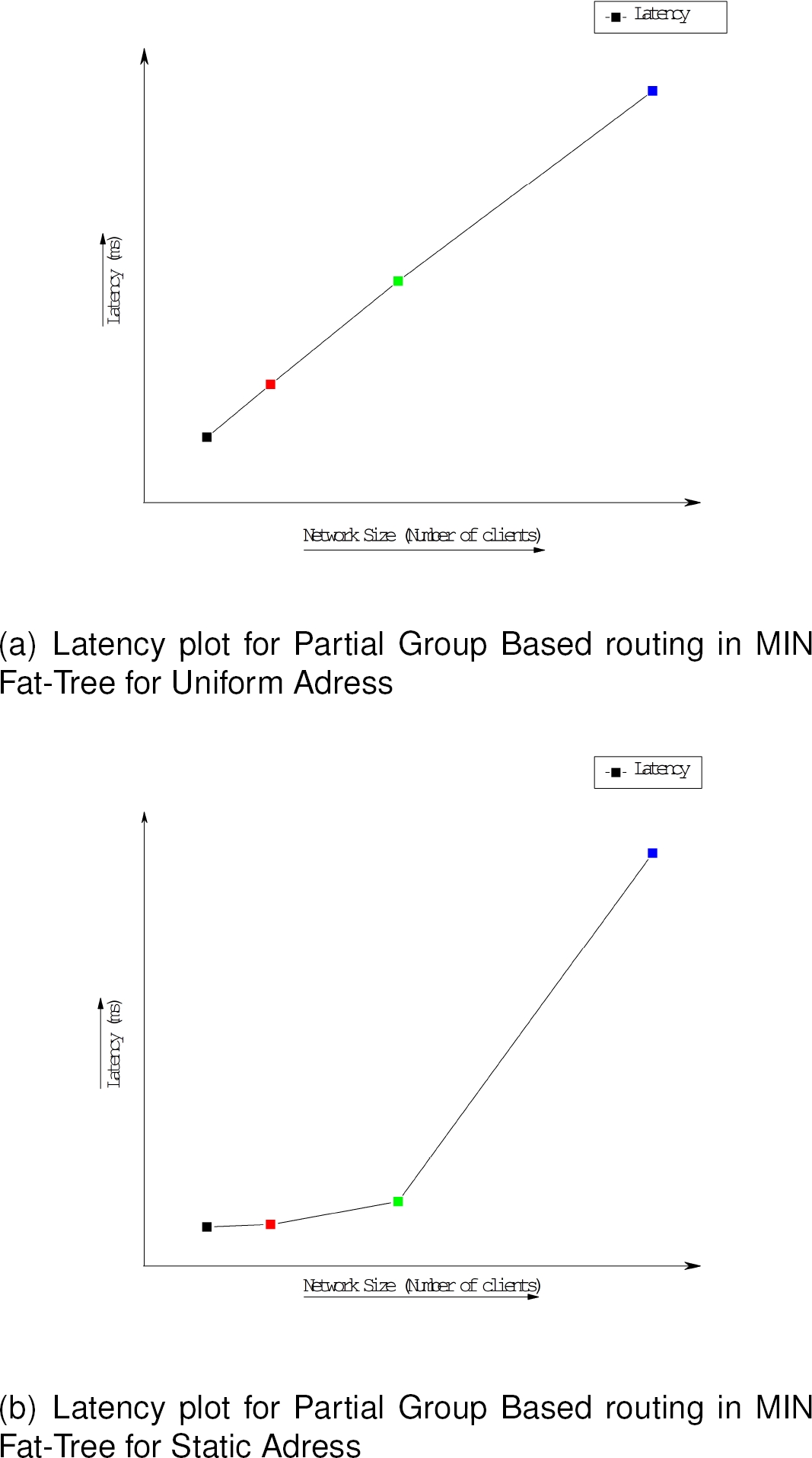
The latency in our network has been computed as the time taken for the first flit to start from the source and till the last flit of the message reaches into the destination client. The Latency graph have been plotted for all the networks and shown in Fig. 7, 8 and 9, finally, the comparison graph is shown in the Fig. 10. The results have been shown as
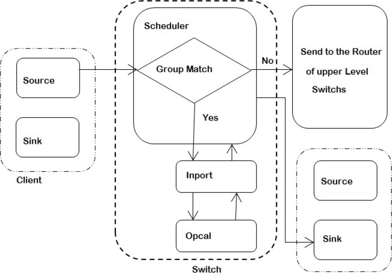

Fig. 7 Figure depicts how the blocks of

Another marker for analyzing simulated network is the hop count, which is, number of hops made by a flit to reach the destination from the source gives the hop count. Also table 1 enlists the maximum hop count for all the tree networks.
Table 1 Comparison of the Hop Count for the three different networks
| Network Size | Maximum HOP count | ||
| Reduce switch Scalable MIN Fat-Tree | Partially Grouped Routing For MIN Fat Tree | MIN Fat-Tree | |
| 8 | 4 | 5 | 5 |
| 16 | 6 | 7 | 7 |
| 32 | 8 | 9 | 9 |
| 64 | 10 | 11 | 11 |
| 128 | 12 | 13 | 13 |
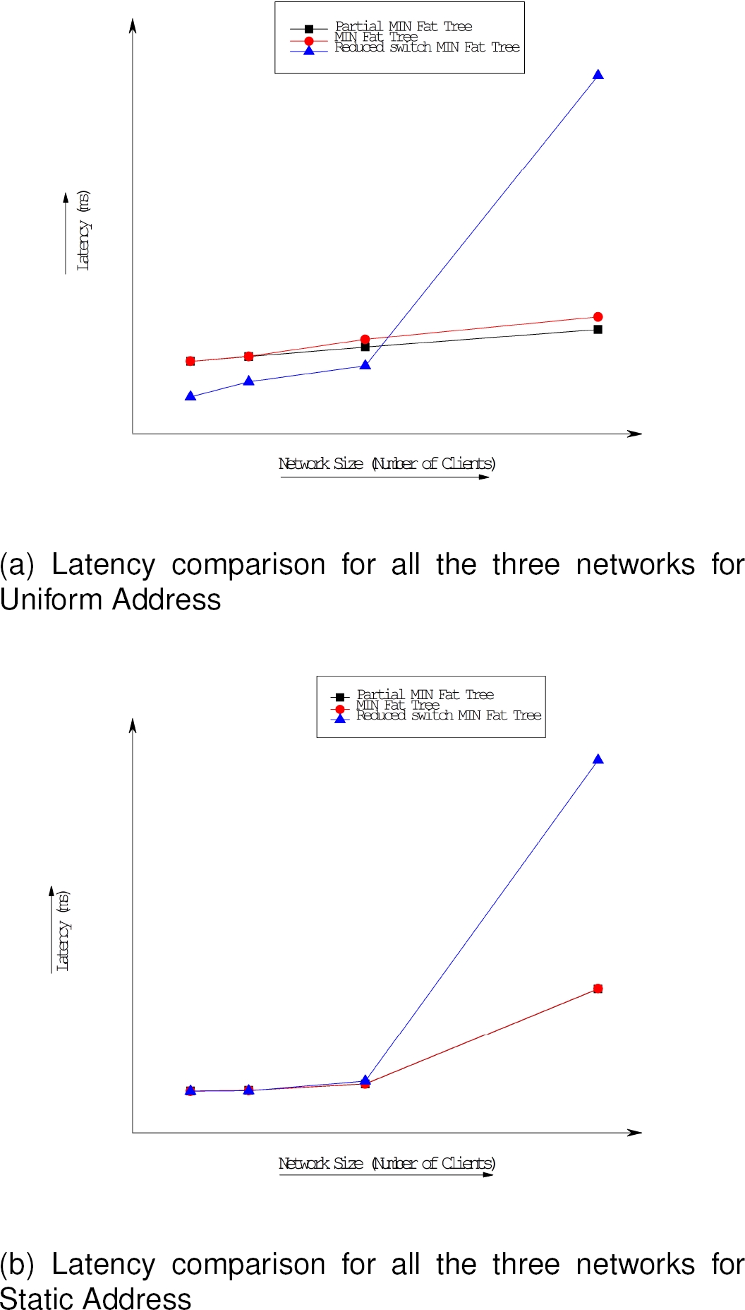
From the figures above it is evident that, partial group based routing in MIN Fat-Trees produces almost similar latency counts for smaller network sizes viz. 8 clients and 16 clients in uniform address scheme, but shows some improvement in higher network sizes viz. 32 and 64 clients as compared to traditional MIN Fat-Tree routing for similar network sizes.
For static address generation scheme partial group based routing and traditional MIN Fat-Tree routing produces almost similar graph.
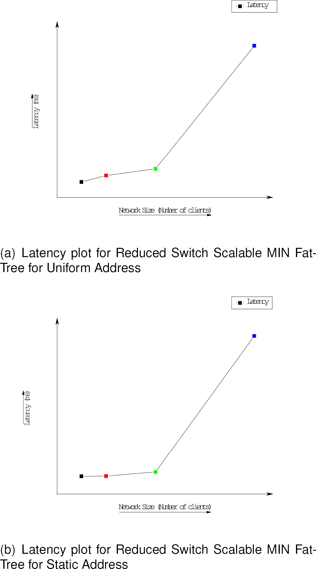
On the other hand, the proposed reduced switch scalable MIN Fat-Tree topology shows relatively improved results for 8, 16 and 32 client size networks under uniform address generation scheme as compared to the other two networks, but shows high latency in bigger networks viz. 64 clients and above.
For static address generation scheme, the reduced switch scalable MIN Fat-Tree shows very high latency count for all network sizes as compared to other two networks.
It can be seen from the table above that, the proposed reduced switch scalable MIN Fat-Tree reduces the hop count by one hop accross all sizes of networks. This is because of the removal of a layer of switches/routers from the top level of the designed networks.
5.2.2 Hardware Size
Another factor of analysis for the proposed reduced switch scalable MIN Fat-Tree was reduction in the number of switches/routers in the network.
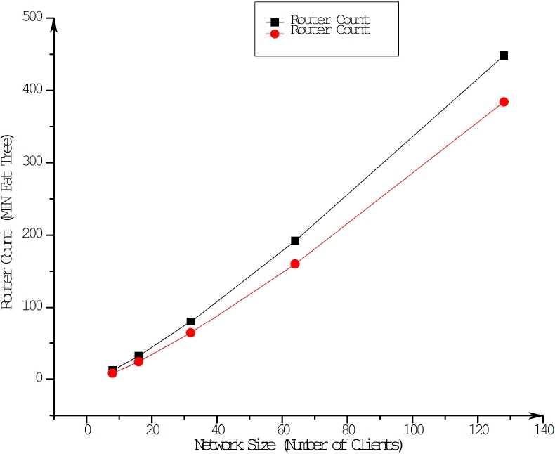
For this purpose, we compared the number of routers in our proposed network with the conventional Fat-Tree used by Bouhraoua et al. [9-11].
It was found that our proposed network could reduce number of routers from 33.33% percent to 14.28% of the routers. For this analysis, we scaled the network size till 128 clients. In Table 3, we have showed in details the number of routers reduced with graphical analysis in Fig. 11.
Table 2 Comparison of the Hop Count for the three different networks
| Network Size | Router Count | ||
| MIN Fat-Tree | Proposed MIN Fat Tree | % Reduced | |
| 8 | 12 | 8 | 33.33% |
| 16 | 32 | 24 | 25% |
| 32 | 80 | 64 | 20% |
| 64 | 192 | 160 | 16.66% |
| 128 | 448 | 384 | 14.28% |
6 Conclusion and Future Work
In this paper we have proposed a reduced switch scalable MIN Fat-Tree for network on chip designs. The proposed network addresses the issue of reducing the size of original MIN Fat-Tree.
The proposed network and its associated routing algorithm is simulated along with MIN Fat-Tree having Partial group based routing and the traditional routing. On careful analysis of the results thus obtained from the simulations, it was found that, the proposed network shows comparable results for network sizes of 8,16 and 32 clients in uniform addressing scheme.
However, the reduction in the switches made in the proposed network is compensated by a higher latency count in all the network sizes for static address generation scheme and for higher network sizes viz. 64 and above clients for uniform address generation scheme. Proposed network in inherently scalable and also reduces the hardware utilized by 33.33% to 14.28%. Although, further reduction in the said network could be achieved, but that is at the cost of scalability of the network. Further, the routing algorithm for the proposed network is free from livelocks and deadlocks.
The present paper attempted to reduce the height of the MIN Fat-Tree by eliminating the topmost row switches, It can be further investigated to see if the width of the network can also be reduced maintaining the scalable property of the network.

