


 nova página do texto(beta)
 Inglês (pdf)
 Artigo em XML
 Referências do artigo
 Enviar este artigo por email
 Citado por SciELO
  Similares em
SciELO
Similares em
SciELO 
 Permalink
1 Introduction
Integrity constraints, or just constraints, are that mechanism used in a database system context to guarantee some level of integrity. They are those system rules, formally represented through Boolean conditions that must be satisfied at all times [43].
According to some authors [19], constraints are more than 90% of the sentences necessary to control the integrity of a database. However, as David C. Hay noticed [25], data modelers are mainly concerned with representing the structure of a business domain, so integrity constraints are "mostly outside the realm of data models".
However, this has a side effect. Constraints, which are not expressed by a conceptual schema, are implemented without being expressed in a clear, systematic and controlled way during the process of conceptual modeling. This leads to a system which either stores and shows false information, or which is not a so faithful implementation due to the incapacity of the domain expert to validate a programmer's code. This problem results from the communication gap between domain experts and modelers: while the modeler has a good technical knowledge about the modeling tools and languages and little knowledge about the domain; the domain expert knows all about the domain, but sometimes he knows nothing about the tools and languages.
According to Snoeck [55], a way of achieving validity is the expression of rules in terms of the domain expert's means of communication, so it would be convenient to use a natural-like expression language. However, verifying that a certain rule is part of the requirements does not guarantee there are no redundancies or contradictions in the set of documented rules. Therefore, it is also necessary to achieve internal validity, for which a formal model is required. Two different levels of expression are then necessary. The first one is understood by the domain expert, and the second one, by the system. Von Halle [58] refers to these levels as the natural language and specification language, respectively.
From a business perspective, some researchers have made a substantial contribution to the problem of integrity constraints expression by introducing the Business Rules Approach. With this radical approach, modelers are not only involved in the modeling process of the system structures, but also in the specification of those constraints that come from business rules [47,58].
On the other hand, database modelers have traditionally used the Entity-Relationship model (ER) to represent the information structure of a problem domain [20]. It is a popular approach where the modelers concentrate on the database structure and constraints during the conceptual database modeling stage. Nevertheless, many types of constraints are not represented in ER schemas, as it is focused on data structure.
Other researchers related to Model Driven Architecture (MDA), a style of software development based on transformations between models, have proposed some methods that take into account a broader set of integrity constraints through all the levels prescribed by MDA [42,13,9]. According to this approach, some terms used are CIM, PIM, and PSM. This is equivalent to a treatment from higher levels of abstraction (CIM), to those linked to a specific technology (PSM), so it is compatible with the database modeling process.
With these results emerges the opportunity to address the issues of expressing constraints identified in a universe of discourse (UoD) during database conceptual modeling. Therefore, we get both the benefit of clarity and formality associated with the Business Rules Approach, and the ER known capacity to represent concepts and relationships between them in a simple way and without losing expressiveness. After all, the ER model has a long tradition in the database community, and it is praised for having drawn the line between expressiveness and simplicity at a good point [5]. Therefore, we propose a framework that allows to achieving both external and internal validity in the specification of constraints.
Specifically, we make the following contributions:
— We identify the ER model as an appropriate means of describing data requirements.
— We describe a set of templates based on Witt's templates [60] in combination with Semantics of Business Vocabulary and Business Rules (SBVR), that allows to express in a natural-like language those data related constraints that the ER model is incapable to represent by any means.
— We identify Alloy as an appropriate language to represent constraints in a formal level.
— Finally, we set the correspondence between the ER model and the language described for expressing constraints, and between the latter and the formal representation language.
Section 2 shows some works related to the expression of integrity constraints. Section 3 describes the problem of the expression of constraints during conceptual modeling and Section 4 proposes how to deal with constraints in conceptual models. The language for expressing constraints during conceptual modeling is explained in Subsection 4.1, while Subsection 4.2 explains the language chosen to accurately and formally represent constraints. The correspondence between all the components of the proposal are described in Section 4.3. Section 5 illustrates the use of the proposed method for expressing and transforming a set of constraints given an ER schema. Finally, Section 6 shows the results of a survey applied in order to empirically support the feasibility of the proposed method from the modeler's perspective.
2 Related Works
In the literature review, we found different approaches to the problem of expressing integrity constraints. In the particular context of the ER model, this problem can be traced back to 1976, when Peter Chen mentioned it in his seminal article [15]. Four decades later, there is an extensive bibliography that we have decided to group into:
— Constraints expression languages: languages that are or could be used to express constraints.
— New and more expressive approaches to conceptual modeling: models with a greater level of expressiveness, so they have the capacity of specifying more types of constraints.
— MDA approaches: they automatically or semi-automatically transform constraints expressed by models from higher to lower levels of expression.
In the first group, the languages are classified according to means of expression, representation, and base model (see Table 1). The means of expression includes visual and textual languages, and a third subgroup called hybrid, describing a combination of the first two others. The underlying logical representation [43], determines whether a certain language is designed or can be used for specifying constraints (specification language) or whether it uses operators for retrieving those cases that correspond to a violation of a constraint (query language). Finally, it is possible to distinguish between languages based on ER concepts, and those which are not.
Table 1 Constraints expression languages
| Author | Representation | Base model |
Means of expression |
Observations |
|---|---|---|---|---|
| Angelaccio et l. [3] | Query | ER | Visual | QBD* is diagrammatic query
language, that allows the user to interact with a database in a fully graphical way. |
| Thalheim [57] | Query | ER | Visual | Visual SQL overcomes the
difficulties of complex SQL queries and, at the same time, follows the ER paradigm. |
| Hohenstein and Engels [28] | Query | ER | Textual | SQL/EER is a high-level query
language. It supports all the constructs of the EER model. |
| Lawley et al. [39] | Query | ER | Textual | ERQL is a query language based
on the EER model, with a defined formal semantics. It improves some aspects of SQL/EER. |
| Andries and Engels [2] | Query | ER | Hybrid | HQL/EER improves SQL/EER by
allowing a user to use both graphical and textual elements in the formulation of the same query. |
| Bloesch and Halpin [10] | Query | Not ER | Textual | ConQuer-II is conceptual query
language based on ORM that allows users to formulate queries naturally in terms of elementary relationships. ConQuer-II queries are automatically translated into English and into SQL. |
| Gogolla [22] | Specification | ER | Textual | Gogolla describes a form of Calculus for the EER model. |
| Kent [37] | Specification | Not ER | Visual | Constraints Diagrams are
proposed for precisely expressing constraints on object-oriented models, as an alternative to mathematical logic notation. It borrows much from Venn diagrams. |
| Ivanov [31] | Specification | Not ER | Visual | A visual notation for
specifying constraints on diagrams of UML classes by means of the UML collaboration diagrams is suggested. |
| Burton [35] | Specification | Not ER | Visual | Spider diagrams are based on
Euler and Venn/Peirce diagrams. It is intended to be used by designers for software specification. |
| Ataullah [4] | Specification | Not ER | Visual | Ataullah proposes a graphical
notation that is equivalent to integrity constraints specified in linear temporal logic of the past. It is a part of a systematic method of mapping a broad set of process centric business policies onto database level constraints. |
| OMG [44] | Specification | Not ER | Textual | OCL is a formal language used
to describe expressions on UML models. These expressions typically specify constraints that must hold for the system being modeled. |
| Jackson [32] | Specification | Not ER | Textual | Alloy is a formal language
based on binary relations that offers a declaration syntax compatible with graphical object models, and a set-based formula syntax powerful enough to express complex constraints and yet amenable to a fully automatic semantic analysis. |
A query language can be used for specifying constraints although its primary purpose is to retrieve data. Indeed, it can be used to retrieve those cases that are the cause of the violation of a constraint. This forces to formulate the constraint in a different way from what was thought by the modeler. In contrast, a constraint specification language is designed to express the constraint as a condition that must be satisfied at all times. Therefore, it translates the underlying logic of the statement directly. However, specification languages like those in Table 1 are not oriented to domain experts, so constraints cannot be validated.
The Object-Role Modeling (ORM) is a conceptual language created by Terry Halpin [23]. It is much more expressive than ER or UML models, and it is an attempt to overcome the deficiencies identified in those models. However, it is the more compact ER model and not the ORM the preferred tool for designing databases [24].
The MDA approaches to constraints representation are classified as top-down and bottom-up. A top-down transformation process begins with a high abstraction representation of constraints, and ends with a lower one. Usually, it targets an implementation level, and starts with a representation closer to the domain expert [42, 34, 11, 1, 33, 8, 30, 52, 51, 12, 9, 40, 26, 50, 27, 46, 21, 36]. A bottom-up transformation process works contrariwise: from a low-level constraints representation, to a higher abstraction level. Cabot [13], for example, uses SBVR for verbalizing constraints expressed in Object Constraint Language (OCL), in order to allow the domain expert to validate the specification; and Chittimalli [17] goes further by expressing SBVR rules extracted from program code. Top-down approaches also use a higher-level abstraction language to isolate the modeler from some of the shortcomings of OCL [7]. The Alloy language creators have also identified some of the OCL limitations, and provided a lite and easy-to-use syntax for their language [32]. Also, a common factor in those proposals is SBVR. It is a specification published by the Object Management Group (OMG), a computer industry standards consortium, which has received the attention from the information system and software engineering communities. SBVR is also a key factor to our proposal.
UML Class Diagrams (CD) are another common factor in MDA approaches. As shown in Table 1, CDs are also a frequent base model for those not ER-based constraints languages. Database designers are using CDs as a means of expression for an ER schema. Even more, many database books have introduced CDs for this purpose [18,20]. However, initial versions of UML originated with object-oriented methods (OO), and the OMG has standardized both its syntax and OO semantics. This forces to adapt UML for ER modeling in different ways. For example, there is no concept of identifier in UML.
Therefore, Connolly and Begg [18] propose to use tags while David C. Hay [25] proposes to use stereotypes. Moreover, there is no direct support of relationship attributes or compound attributes in CDs. Conversely, the ER model does not support class operations. Other constructs such as aggregation and composition are not represented in an ER model, either. They do not have different structural properties, and the choice as to which type of relationship to use (aggregation or composition) is somewhat subjective [20].
From a teacher's perspective, we have to explain to students how to use and think about CDs in the context of ER modeling, due to the difference between data architecture and OO design [25]. Because we are interested in data conceptual modeling, we use an ER diagrammatic technique.
3 Integrity Constraints in Data Conceptual Modeling
From data perspective, a conceptual schema is "a concise description of the data requirements of the users and includes detailed descriptions of the entity types, relationships, and constraints" [24]. These are expressed by means of a high-level data model; and the task of conceptually modeling a domain is intended to be executed by humans instead of machines, so a key is to express a conceptual schema in terms of concepts readily understood by a domain expert [23].
Conventionally, conceptual database design is dominated by the use of the ER model [24]. However, as noticed by Badia [5], this model is limited regarding its capacity for expressing some types of constraints identified during the requirement specification phase. Therefore, current design approaches mostly ignore these semantically relevant requirements [6]. According to Simsion [54] and Olivé [43], the ER model is only capable of expressing:
— Key constraints.
— Referential integrity constraints.
— Cardinality constraints.
— Participation constraints.
— Inclusion constraints (through generalization/specialization relationships).
— Constraints on which entity can be associated with each other (by specifying that a relationship is with a subtype of an entity type rather than the entity type itself, or an entity type is existence-dependent on certain entity of another entity type).
— Domain constraints over an attribute (whether each attribute is required, data types and set of categories, although not directly recognized by the ER model, can be easily documented by means of a CASE tool).
Although an ER model is capable to represent all these constraints, some types left cannot be modeled due to either their complexity or nature [56]. A trained modeler can easily check there is no possible ER representation for the following constraints:
— The new name specified in each application form must be different from the previous name specified in that application form.
— The combination of start date and end date specified in each project must be such that the end date is later than the start date.
— The number of passengers specified in each flight must be at least 50.
3.1 Origin and Levels of Expression
Ronald Ross defends the idea that integrity constraints differ from so-called business rules in a fundamental respect: while the former belong to the system, the latter are "under the business jurisdiction" [48]. However, an integrity constraint does not exist if it is not previously imposed or inferred by the modeler. Therefore, even if the term business rule is reserved for the business, integrity constraints have their origin directly or indirectly in them. We are just in presence of two different levels of expression according to whether the "jurisdiction" is the business or the system. As stated in [58], there are different levels for expressing a constraint: the informal version, the natural language version, the specification language version and the implementation language version.
Von Halle [58] explains that a constraint begins its life in the informal business conversation. Then, it is transformed into a more disciplined version of a natural language whose audience is the business community. This controlled natural language has still some limitations such as lack of precision, so another version is required. Such is the case of the specification language. It is declarative and disciplined, and its intended audience is both the business and the IT staff. Additionally, this language has no effect on the system states, as it is oriented to specify constraints. Therefore, constraints are transformed into the implementation language, which has the potential to be executed.
3.2 Classification
As there are some types of constraints that cannot be represented by the ER model, it is necessary to specify the ones that must be analyzed in order to provide adequate support for their expression.
From a business point of view, only those constraints that are derived from operational business rules (obligation or prohibition statements) [45] are of interest. The ER model cannot represent such constraints, which is only capable of representing constraints derived from structural business rules (necessity or impossibility statements) [45]. However, not every operational business rule can be implemented or is relevant to a system. It depends, largely, on the capacity to operationalize a business rule. Operationalized means that the desired effect of the rule in a business can be obtained by having it executed by a computerized system [16].
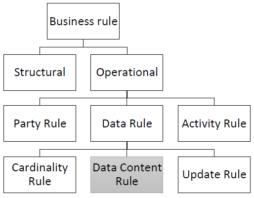
Witt describes a more detailed classification of business rules (Fig. 1). As stated above, we are only interested in operational and operationalized business rules, so activity rules and party rules are out of scope and their documentation is only of interest to the business. The classification also introduces other types within the operational data rule type. However, an ER schema can represent cardinality rules. Consequently, only update rules and data content rules are subject to be operationalized, but we have focused on integrity constraints derived from data content rules.
From a formal point of view, integrity constraints can be classified according to scope and cause of violation [43].
In this regard, we are only interested in static constraints where a violation is caused by events.
4 Proposal
It is possible to obtain a more disciplined version of a business rule by means of a Controlled Natural Language (CNL). A CNL is a "constructed language that is based on a certain natural language, being more restrictive concerning lexicon, syntax, and/or semantics, while preserving most of its natural properties" [38]. Such a language has the desired properties of a conceptual language, as it can be designed to have independence from implementation details and to facilitate human communication, understanding, and validation [24].
The lack of precision is one of the characteristics that is usually associated with CNLs. Therefore, in the best scenario, the rule is documented by the modeler in a natural sentence, and then is delegated to the programmer. According to Halpin and Morgan [24], there have been some attempts to obtain an implementation version directly from a sentence in a CNL. The result is a lack of authenticity due to the large gap between the two levels. Hence, precision is a property of the conceptual model that cannot be negotiated.
At the same time, the natural expression of a constraint at the conceptual level is also a requirement that should not be avoided. That is why we need a specification language for bridging the gap between the conceptual level and the implementation level. Maybe a domain expert cannot deal with such a language, but a modeler will be well equipped to deal with the logical subtleties of a constraint.
In consequence, we propose a method for expressing integrity constraints during the conceptual modeling phase of a database (Fig. 2). It has three components: an ER schema, a controlled natural language based on SBVR for expressing those constraints not represented by the ER schema, and Alloy, a simple but expressive language for specifying an implementation independent model of the structure and constraints of a domain.

4.1 Expression of Constraints in a SBVR-Based Controlled Natural Language
The SBVR is a specification published by the OMG. It is not really a CNL, but a disciplined and formalized way to share vocabulary and business rules between organizations and software tools [45]. In addition, it is based on first-order logic, with an extension of modal operators and second-order logic with Henkins semantics. The purpose of using SBVR is to design a transformation process independent of the notation and, in consequence, the language (multi-lingual). This is possible because of SBVR's concept-centric approach [14], so the expression is separated from its meaning. In addition, with SBVR it is possible to obtain an unambiguous definition, apart from a formal interpretation of the meanings of business concepts and rules.
Properly constructed natural language constraints may provide both the domain expert and the modelers with the necessary information. However, unless carefully created, they may be ambiguous or vague. Thus, it is necessary to use a more restrictive version of the natural language while its comprehensibility is maintained.
Ronald Ross is the author of RuleSpeak, a well documented [47,45] CNL that has been used with business people in actual practice in large-scale projects. It is SBVR-compliant and, although originally conceived in English, already has versions in other languages. However, the sentence forms described in [49] allow for considerable freedom, so it is difficult to achieve quality constraints.
Graham Witt, on the other hand, proposes a controlled natural language including the best experiences with RuleSpeak but overcomes the difficulty to assure quality. The CNL described in [60] is designed to help modelers to specify an organization's business rules using natural language in a clear, succinct, unambiguous, and consistent manner. That is why we have selected and adapted the templates proposed by Witt in his book [60] to deal with constraints based on an ER schema.
4.1.1 Purpose and Notation of Templates
Templates are a very popular approach to help business analysts in the process of writing business rules. They are possible syntactic structures of a CNL, patterns in a natural language used to express constraints in a well-organized and consistent manner [49]. Their purpose is to ensure that a domain expert easily understands a constraint, but in a way that different members of the same speech community can express the same ideas in the same manner. In no way they define a formal grammar of a language, but rather simplify the base natural language [38].
According to [60], there are various places in a template where any term or verb phrase can be substituted. A label enclosed in angle brackets indicating the type of word or phrase by which it will be replaced will denote these placeholders. In addition, a font style and a color distinguishes the placeholders. This practice proposed in Annex A of the SBVR specification helps a person to recognize the integral parts of a restriction quickly. Table 2 shows the five types of placeholders, their font styles and colors.
Table 2 Types of Placeholders in the Templates
| Placeholder | Description |
|---|---|
| <term> | A term is a designation
for a noun concept, one that is part of the vocabulary. |
| <literal> | A literal is a designation
for an individual noun concept. Literals tend to be names, numerical values, date or time values. |
| <verb phrase> | A verb phase is a
designation for a verb concept. It is usually a verb, preposition, or combination thereof. |
| <keyword> | Keywords are used for
linguistic symbols used to formulate sentences and propose definitions. |
| <symbol> | It designates a
subtemplate. A subtemplate is a template for a syntactic element that may appear in more than one type of constraint. |
4.1.2 Keywords
The terms, literals and phrases are usually linked to the problem domain. However, the keywords represent those words or phrases that are frequently used to construct a sentence. Therefore, the most frequent phrases such as quantifiers, logical operators and modal operators are predetermined and designate concepts defined in SBVR. The keywords used are explained in Annex A of the SBVR specification [45].
Annex A introduces prefixing rule keywords and embedded equivalent keywords, but only the embedded alternative is used.
4.1.3 Templates for Constraints
The first type of data content rule are the constraints derived from range rules. They require certain values to be within an open or closed range, with one or two bounds. For example:

These constraints can be written by means of the template shown in Fig. 3.
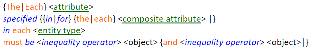
Both attribute and the composite attribute are not concepts of SBVR, but definitions based on it. They correspond to the simple and composite attributes in the ER model, respectively. However, knowing this correspondence is irrelevant as it is centered on the concept.
This will be explained later in section 4.3.1. Likewise, the placeholder <entity type> is a term corresponding to an entity type in the ER model, and it is optionally followed by a qualifying clause. In contrast, the placeholder <object> is not a term, but a predicate following the main verb phrase of the constraint. As it is a range constraint, this predicate is related to the range bounds. There are fixed and variable bounds. A fixed bound is usually a number or a date value, while a variable bound is some term related to the constrained term.
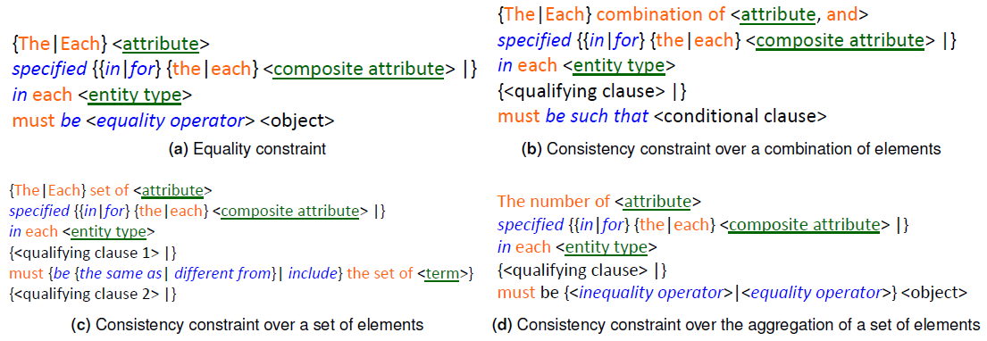
If we follow the taxonomy within a data content rule, then there are some other possible templates. These templates are depicted in Fig. 4, and are mostly based on Witt's proposal [60].
4.2 Expression of Constraints in Alloy
Although more unambiguous and consistent, the proposed templates are not as precise as a specification language. Therefore, we still need to express the constraints that cannot be specified through an ER schema in the selected specification language: Alloy. For this reason, we summarize some Alloy mechanisms for expressing constraints.
4.2.1 Alloy Fundamentals
According to Daniel Jackson [32], Alloy combines three logics in one: relational algebra, predicate calculus and a navigational expression style. With "logics", Jackson means expression styles based on predicate calculus and relational algebra with the relevant inclusion of the transitive closure operator. For example, consider the following constraint:

This constraint is written as a natural language expression, and could be translated to Alloy in the three alternatives:
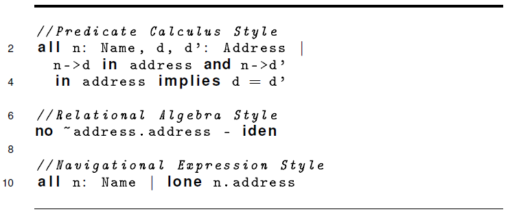
The first style is too verbose, but is clearer than the relational algebra style, where expressions tend to be obscure. However, the navigational style, combining both the calculus and the algebra styles, is often more concise without losing clarity.
4.2.2 Constraints in Alloy
Alloy not only offers three alternatives for expressing a constraint according to its base logic, but also classifies them according to their function during their modeling process. A fact is used for expressing those constraints that are already part of a model. An assert expression is used for checking the validity of a model when a new constraint is introduced. That new constraint is known in Alloy as a predicate. This points towards a methodology for system modeling where constraints are incrementally added to a model and checked one by one, beginning their life-cycle as a predicate, then as an assert expression, and finally, as a fact. As the Alloy constraints will be obtained from the translation of SBVR concepts, it is advisable to code them through a predicate expression. For example:

The corresponding predicate expression in Alloy will be:

4.3 Correspondences and Mappings
As Fig. 2 suggests, it is necessary to find the correspondence between the ER model and SBVR on the one hand and the mapping between ER+SBVR and Alloy on the other. The correspondence obeys to the necessity of having a coherent representation of the domain with these two different conceptual models.
The mapping is related to the fact that both the SBVR based constraint and an ER schema, have to be transformed into an Alloy model.
4.3.1 Correspondence Between ER and SBVR Models
Although both are known as conceptual models [24], SBVR is based on a model that is different from the ER model. Actually, SBVR is based on a fact-oriented modeling approach [24]. This approach enables one to model information in terms of the underlying facts of interest about objects. It is also attribute-free. This means that every fact is treated as a relationship between objects (entities or values), so this is the main difference from the ER model.
Despite the differences between both models, a fact model can be used as the basis for the creation of an ER model, with more business-friendly terms [60]. This means that there is a correspondence between them.
Therefore, Table 3 shows the correspondence between the concepts of the SBVR interpretation of the fact-oriented modeling approach, and the ones of the ER model. It was obtained by semantically equating the concepts from both models.
Table 3 Correspondence Between the Concepts of the ER Model and SBVR
| ER model | Meaning in SBVR | Representation in SBVR |
|---|---|---|
| Entity type | general concept | term |
| Attribute |
verb concept role of the property association |
term |
| Association
between an entity type and a binary attribute |
unary verb concept | verb concept wording |
| Relationship type | binary verb concept verb | concept wording |
| N-ary relationship type | general verb concept | verb concept wording |
| Association
between an entity type and one of its non-binary attributes |
property association | verb concept wording |
4.3.2 ER2Alloy Mappings
Some researchers [41] have already studied Alloy mapping onto UML class diagrams, but that is not the case with the ER model. This is probably caused by the extensive use of UML class diagrams in the MDA platform. However, due to the similarities between UML class diagrams and ER diagrams, we must take into account these results. Table 4 shows a correspondence between basic concepts of the ER model and equivalent expressions in Alloy.
Table 4 Correspondence between ER and Alloy
| ER model |
Alloy | Example |
|---|---|---|
| Entity type | Signature declaration |
sig employee{} |
| Attribute | Field
declaration with one multiplicity |
sig
employee{idemp: Tidemp, namemp: Tnamemp, age: Tage} |
| Identifier | Fact
uniqueness declaration |
fact
{#employee = #employee.idemp} |
| Domain | Signature declaration |
sig Tnamemp{} |
| Value | Singleton
signature declaration |
one sig john extends Tnamemp{} |
| Relationship type | Relation declaration |
one sig
works{ rel: employee some -> lone bank} |
We have obtained this correspondence by choosing the Alloy expression that, in our criteria, is the best match for every ER concept analyzed. For example, Alloy provides the mechanism of fields for representing the association between two signatures. However, we chose to use signatures for representing both the entity types and the relationship types. We think this captures the relationship set semantics more accurately, and provides its own structure. In addition, we proposed a more compact representation for identifiers, based on the Alloy's relational algebra style.
Regarding the representation of the domains and their values, Alloy does not have an integrated type system. Instead, everything in Alloy is a relation and there are no other data types, nor the distinction between sets and scalars.
Jackson [32] argues that such a design decision provides simplicity, uniformity and power of abstraction. In addition, it is a conceptual modeling language in which everything related to the computational system must be avoided. Therefore, as a domain is simply a set of values, we use signatures for its representation. In the case of discrete values, we use a signature with multiplicity one, a set of a single value. We must notice that, even when the Integer data type is available in Alloy, it is reserved for dealing with cardinality expressions of relations. If it is necessary to use them, then the problem must be rethought and a more abstract representation sought.
Moreover, if we are dealing with a problem of numerical nature, then perhaps Alloy is the least appropriate language.
4.3.3 SBVR2Alloy Mappings
For mapping an Alloy expression onto its source SBVR constraint, we also have to obtain a correspondence between the concepts of these two models. For this, we use the logical formulation associated to constraints that are written through one of the templates shown in Fig. 3 and Fig. 4. Logical formulations in SBVR are not a formal language in which a rule can be rewritten, but a means of documenting the logical structure of meaning [45]. Therefore, the intention is to develop a concept-centric transformation approach. Since the Alloy language and SBVR logical formulations are basically first-order logic, the correspondence between the two is not difficult to obtain.
Every closed semantic formulation uses a quantification for introducing a variable. A variable ranges over the concepts represented in a constraint. So, for every new concept, a variable and its quantifier must be introduced. Table 5 shows the correspondence for quantifiers.
Table 5 Correspondence between quantification concepts in SBVR vocabulary for logical formulations and Alloy quantifiers
| SBVR | Alloy |
|---|---|
| universal quantification | all x: e | F |
| existential quantification | some x: e | F |
| at-most-one quantification | lone x: e | F |
| exactly-one quantification | one x: e | F |
Logical operators are explicitly available in both models. Therefore, the correspondence is very straightforward with the exception of the exclusive disjunction, for which an equivalent logical formulation was provided. The correspondence is shown in Table 6.
Table 6 Correspondence between logical operators concepts in SBVR vocabulary for logical formulations and Alloy logical operators
| SBVR | Alloy | |
|---|---|---|
| logical negation | not | ! |
| conjunction | and | && |
| disjunction | or | || |
| exclusive disjunction | (not p and q) or
(p and not q) |
( ! p
&& q) || (p && !q) |
| implication | implies | => |
| equivalence | iff | <=> |
In the particular case of comparison operators, there are some concepts already defined in SBVR.
However, they do not include adequate verb concept wordings for dates, and have a reduced set of synonymous forms for every operator. This is not a limitation in any regard, as the solely purpose of SBVR is to serve as the basis to formulate a business vocabulary and rules. Therefore, we have defined a list of verb concepts for comparison operators, and set the correspondence between them and the ones from Alloy language (Table 7).
Table 7 Correspondence between SBVR-based verb concepts and the comparison operators in Alloy
| SBVR | Alloy |
|---|---|
|
general
concept1 is the same as
general concept2 |
= |
|
general
concept1 is different from
general concept2 |
!= |
| quantity1 is equal to quantity2 | = |
| quantity1 is unequal to quantity2 | != |
| quantity1 is less than quantity2 | < |
| quantity2 is more than quantity1 | > |
| quantity1 is no more than quantity2 | =< |
| quantity2 is no less than quantity1 | >= |
| date1 is no earlier than date2 | >= |
| date2 is no later than date1 | =< |
| date1 is earlier than date2 | < |
| date2 is later date1 | > |
| set1 includes set2 | in |
Unlike SBVR, in which we are able to distinguish different types of data, in Alloy, there is no distinction between scalars and sets, and there are no previously interpreted data types either (numeric, integer, string, Boolean). Therefore, the comparison operators are the same for all data types.
5 Case Study
From the correspondences described between the components illustrated in Fig. 2, the process of obtaining an Alloy model given an ER schema and a SBVR-based constraint can be summarized as follows:
Validation: to check that each term is expressed as an entity or an attribute, and a verb concept wording is either a relationship type or an association between and entity type and an attribute.
Transformation from ER to Alloy: to obtain the equivalent structures in Alloy given an ER schema.
Transformation from SBVR to Alloy: to obtain the equivalent expression in Alloy to an SBVR-based constraint.
In order to illustrate the transformation process using the described correspondences, we have created a case study based on another from [42]. This case study shows the main concepts of the ER model (Fig. 5a), for which we provided a set of constraints that are representative of every type described (Fig. 5b). These constraints are the result of using the templates from Fig. 3 and Fig. 4 although in a common scenario they would be elicited from records, forms, subforms or transactions.

5.1 Checking for Validity
The first step is very straightforward. Using the correspondence shown in Table 3, we are able to check that every term is expressed in an ER schema as an entity type or an attribute. For example, C1 in Fig. 5b has two terms: amount and Loan. Both are represented as an attribute and an entity type respectively in Fig. 5a.
Likewise, we have to check that every verb concept wording is expressed as an association between an attribute and an entity type, a relationship type, or a predefined verb concept wording. In C1, there are three verb concept wordings: specified for, be no less than, and no greater than.
The first one connects the terms already identified, and corresponds to the association between the attribute amount and the entity type Loan. The second and the third one, have no counterpart in the ER schema, but they are the main verb concept wordings on which the constraint is based to compare the term amount to the quantities 50 and 10 000.
Therefore, it is fair to conclude that C1 is a constraint based on the ER diagram from Fig. 5a. However, we must notice that a verb concept wording may be different from the label used in its equivalent. For example, it is unlikely to find specified for and its variants in an ER schema. It is recommended in the templates for connecting terms in the subject of a constraint statement that are usually linked in an ER schema by an attribute-entity-type kind of association.
The same happens with C4, where the relationship label connecting the entity types Person and Loan is gets, while the verb concept wording used is Person in Loan. Therefore, we just need to look for an association between an attribute and an entity type, or a relationship between two or more entity types despite the label used.
5.2 Transforming an ER Schema to Alloy
The second step is to transform the ER schema into the corresponding Alloy structures. In Table 4, we show that each entity type can be transformed into an Alloy signature; and its attributes into field declarations. From line 16 to 46, Fig. 6 shows the Alloy code obtained for every entity type in the ER diagram. After each signature declaration corresponding to an entity type, there is a fact constraining the field that represents the identifier. For example, line 19 shows a fact declaration that sets the cardinality of the entire signature Person equal to the cardinality of the set of code. As both the Person.code expression and the Person signature evaluate to sets, then the code field is always unique. Domains and values are expressed as signatures as well. Both are just abstractions of domains and values, and no specific semantics is captured here.

Loan, AcceptedLoan and RejectedLoan participate in a hierarchy, as Fig. 5a shows. Alloy signatures are designed to support this kind of representations accurately. Line 37 shows the Loan signature with an abstract declaration. This tells Alloy analyzer that the Loan signature has no atoms. If there exists an atom, it must be in one of the subsets. A subset expression in Alloy is denoted by the words extends or in.
When two or more signatures extend another, then the extending signatures are disjoint. If the word in is used instead, then they are overlapped. This explains why lines 45 and 46 show two signature declarations that extend the parent signature Loan. We must also notice that the fact expression for representing an identifier of an entity type, is only added once in the Alloy code obtained from a hierarchy in an ER diagram, as the extending signatures are just subsets of the parent signature (see line 43).
All binary relationship types are transformed into Alloy relations. Lines 56 to 60 show five signatures for the five binary relationship types found in Fig. 5a. In every signature, there is a relation between the signatures representing the involved entity types. The cardinality and participation constraints are represented through the Alloy multiplicities one, lone, some, and set. Thus, in a declaration like the one in line 56, zero or more members of Loan are related to exactly one member of Person. While in line 58, at least one Account is related to exactly one Person. In a way, this is a kind of minimum and maximum look-across style; while in the notation of Elmasri & Navathe used in the ER diagram, the style is minimum look-here (represented as a participation constraint) and maximum look-across.
The recursive relationship belongsTo, is also transformed into an Alloy relation. However, to represent this in Alloy it is necessary to materialize the roles in the recursive relationship as signatures like in lines 48 and 49. Then, the recursive relationship is also represented as a binary relationship. Additionally, some facts must be added in order to represent the semantic of this kind of relationship more accurately. Line 52 shows that all banks play one role or another, 53 that a bank cannot be related to itself, and 54 that the relation is acyclic.
A weak entity type is always weak regarding some other entity type. Therefore, this involves both the entity type and the relationship type that links to the regular entity type. The effect on the transformation process to Alloy is the fact expression regarding the identification. Lines 43 and 44 show an Alloy code for the identification of the weak entity type Loan.
This fact is equivalent to say that for each member of Person, the number of members of Loan must be equal to the number of requestDate. In other words, the requestDate is unique in the context of a certain Person.
5.3 Transforming SBVR-Based Constraints to Alloy
Based on the correspondence between Alloy operators and concepts from logical formulations in SBVR, it is possible to obtain an equivalent predicate expression for every constraint in Fig. 5b. The keyword each in a template embeds a universal quantification, while the keyword and is a logical operator. Of course, a quantifier always introduces a variable. In the case of the C1 constraint, the universal quantification introduces a variable that ranges over the concept Loan. The underlying verb concept quantity2 is no less than quantity1 has two roles. The first one binds to the variable that ranges over the concept amount. The second role binds to the unitary variable that ranges over the concept 50.
Therefore, line 62 shows the equivalent code in Alloy. The quantifiers, logical operator, and comparison operator are obtained by mapping them to their counterpart in the logical formulation of C1. Those mappings are based on the correspondence established in Tables 5, 6, and 7. Line 64 shows a very similar constraint that is the result of the transformation of the C2 range constraint. The date literal is the only fundamental difference from C1, but this has no effect on how it is transformed into Alloy.
The cardinality operator is used in every constraint in Alloy involving a signature that represents a numeric concept. This is a resource added to simulate expressions in Alloy involving quantities, as it is an abstraction language with no integrated type system. Instead, we encourage the modeler to use more abstract concepts for denoting range bounds. That is why a range constraint like C3 has a dynamic bound instead of a fixed one. Compared to C1, the C3 constraint involves more than one entity type through the qualifying clause that gives that Loan.
So, the underlying verb concept Bank gives Loan is transformed into a join expression in Alloy. For this purpose, the dot notation is provided (see lines 65 and 67).
The C4 equality constraint is very similar to the previous ones in terms of structure. In fact, it is its use what differentiates them. In general, equality constraints are required when some data must be verified previous to some operation. For example, if, as in C4, it is requested for a person to live in the same city as the bank for giving and approving a loan, then an equality constraint must be formulated. The equivalent expression in Alloy for the C4 constraint is shown in line 67. The underlying verb concepts Person gets Loan and Bank gives Loan are transformed to join expressions to both sides of the equality operator.
In a consistency constraint over a combination of elements, there is more than one constrained element. Moreover, those elements are always terms representing attributes of the same entity type. This is the difference from a range constraint. Consequently, we cannot write any object after the main verb concept wording. Instead, we are only able to write a conditional clause. This conditional clause embeds a condition that must be satisfied for each combination of elements. Line 69 shows the Alloy code obtained.
Aggregation is also possible with an SBVR-based constraint. The C7 constraint is a consistency constraint over the aggregation of a set of elements. Although other aggregation functions are possible, the template in Fig. 4d only includes the set cardinality operator. The equivalent expression in Alloy is shown in line 70. In this case, the cardinality operator accurately captures the semantics of the keyword The number of.
The transformation of the C6 constraint from Fig. 5 is similar to that of the equality constraints. That is why it is not shown in Fig. 6. The difference from an equality constrains is the comparison between set values instead of single values. This comparison can be also established between the set of instances of an entity type, as it is the case in C6.
6 Evaluation
In order to evaluate the usability of the proposed method, we have conducted an empirical study over a sample of 30 students, who held a bachelor in Computer Science or in Software Engineering. They attended a Master's degree course on Models for Data and Knowledge Management where the proposed method was taught, after which they spent one month to analyze a case study and design a conceptual schema in order to develop a database system. Each student was asked to model the same case study with the following methods: UML Class Diagrams with OCL constraints (UMLOCL) [44], ORM [23], Extended Entity-Relationship approach (EER) [20], and the proposed method.
To evaluate usability, we selected some of the factors involved in the modeling process of the method. There are also many descriptions in literature of factors or attributes that contribute to usability. According to ISO 9241-11, usability is the "extent to which a product can be used by specified users to achieve specified goals with effectiveness, efficiency and satisfaction in a specified context of use" [29]. Weichbroth [59] conducted a rigorous literature review and showed that efficiency, satisfaction, learnability and effectiveness were the most frequent attributes referred to in literature. A more recent study aimed to measure the perceived effectiveness and perceived efficiency on model-driven architecture techniques [53]. In consequence, we have selected the perceived effectiveness and efficiency as factors for having an estimate of the method usability.
In our study, perceived effectiveness is the degree to which the intended goals of conceptually modeling a domain, specifically integrity constraints, are achieved by the proposed method. Perceived efficiency, on the other hand, is the degree to which resources such as mental effort must be expended to use the proposed method.
We applied a questionnaire adapted from [53] to each student, for each model being compared. Each dependent variable (perceived effectiveness and perceived efficiency) is associated with four closed questions.
Each question has a Likert scale of five items (1= Strongly disagree, to 7=Strongly agree). Before applying any statistics, we analyzed the reliability of the multi-item scale. The Cronbach's α > 0.8 shows that the scales are reliable for both the perceived efficiency and the perceived effectiveness (See Table 8).
Table 8 Reliability scores for perceived efficiency and perceived effectiveness. Cronbach's alpha values
| Proposed Method |
UMLOCL | ORM | EER | |
|---|---|---|---|---|
| Perceived Efficiency |
0.9004651 | 0.85826 | 0.9264641 | 0.8832984 |
| Perceived
Effectiveness |
0.8198758 | 0.8319709 | 0.8127624 | 0.8185452 |
We used a one-sample t-test for testing the alternate hypothesis: the perceived effectiveness and perceived efficiency of the proposed method are greater than the mean value μ = 4 (neither agree nor disagree). As shown in Table 9, both p-values are smaller than a 0.01 significance level.
Table 9 Perceived efficiency and perceived effectiveness of the proposed method. One-sample t-test, N=30 and μ = 4
| Mean | SD | t value | p-value* | |
|---|---|---|---|---|
| Perceived Efficiency |
4.916667 | 0.799925592 | 4.4382 | 0.000281 |
| Perceived
Effectiveness |
6.233333 | 0.437797518 | 19.757 | 6.344e-12 |
* 99% confidence interval.
Therefore, the null hypothesis is rejected, and that is why we can state that the actual means of the perceived efficiency and perceived effectiveness are significantly greater than 4. In other words, the subjects perceive the proposed method as an efficient and effective one.
However, there are some interesting differences in the mean values of the variables. Although both are greater than 4, the mean of the perceived effectiveness is greater than that of the perceived efficiency. In addition, the standard deviation is smaller in the perceived effectiveness. This seems to point out that the subjects perceived a greater effectiveness in the proposed method than an efficiency, and agreed on that perception. This situation may be related to the fact that the proposed method lacks tooling support. Although they claim that the method enables them to do more important things about the model construction that are not possible without the method, they also rate with lower values the statement related with the temporal efficiency of the modeling tasks.
However, how the proposed method compares to the other three? In order to answer that question we applied a Friedman's test. Regarding perceived efficiency, the P - value computed by Friedman Test is 1.367e-06. In the same way, the P-value = 7.351e - 06 computed regarding the perceived effectiveness is lower than a significance level of α = 0.05. Therefore, the null hypothesis is rejected at a significance level of α = 0.05 in both cases. Then, we are able to state that there is a significant difference between the four methods. Table 10 shows that the proposed method is the best ranked regarding perceived effectiveness, but the worst in the case of perceived efficiency. However, this test does not show which methods are significantly different from the proposed method.
Table 10 Average rankings for the methods. Bold values show the best ranks. Friedman's Rank test
| Proposed Method |
UMLOCL | ORM | EER | |
|---|---|---|---|---|
| Perceived Efficiency |
3.600 | 2.967 | 2.300 | 1.133 |
| Perceived Effectiveness |
1.533 | 2.700 | 1.967 | 3.800 |
Therefore, it is necessary to call the Bergmann and Hommel's procedure in order to perform an all-pairwise comparison. Table 11a shows that the proposed method has a significant difference with ORM and EER regarding perceived efficiency.
Table 11 All-pairwise comparison between the four methods. P-values < α = 0.05 are shown in bold. Bergmann and Hommel's procedure
| (a) Regarding perceived efficiency | ||||
| ProposedMethod | UMLOCL | ORM | EER | |
| ProposedMethod | n/a | 0.179 | 0.017 | 0.000 |
| UMLOCL | 0.179 | n/a | 0.157 | 0.000 |
| ORM | 0.017 | 0.157 | n/a | 0.027 |
| EER | 0.000 | 0.000 | 0.027 | n/a |
|
(b) Regarding perceived effectiveness | ||||
| ProposedMethod | UMLOCL | ORM | EER | |
| ProposedMethod | n/a | 0.040 | 0.358 | 0.000 |
| UMLOCL | 0.040 | n/a | 0.120 | 0.040 |
| ORM | 0.358 | 0.120 | n/a | 0.000 |
| EER | 0.000 | 0.040 | 0.000 | n/a |
Subjects are encouraged to model those integrity constraints not expressed in an ER schema. So, they are expected to perceive the EER approach more efficient than the proposed method.
Regarding ORM, the procedure shows a difference at a significant level of α = 0.05, but there is not enough evidence to reject the equality hypothesis at a level of α = 0.01. In consequence, the proposed method is perceived at least as efficient as ORM and UMLOCL.
In contrast, Table 11b shows that the proposed method is perceived as more effective than EER and UMLOCL, but has no difference with ORM at a significance level of α = 0.05. OCL has been recognized as a specification language with some usability problems that make its adoption difficult [7]. It is only not impossible to understand by a domain expert, but also has a difficult syntax, an ambiguous nature and low understandability of overly complex expressions commonly used in large software models. As for the ORM, it is necessary to note its ability to capture more types of integrity constraints than EER and UML Class Diagrams, while focusing only on those aspects of the domain that are conceptually relevant. That is why, ORM helps the modeler to focus more on the ultimate goals of conceptual modeling and to do more important things about modeling that were impossible without it.
However, the simplicity and popularity of the ER model supports the idea of using it instead. A modeler familiar with this approach will find it easier to accept and adopt the new language, as they only have to use the proposed templates to write those integrity constraints that cannot be represented in an ER schema. This is why the subjects perceive the proposed method as more effective, as it allows them to model more constraints and to fulfill the assigned task.
Additionally, the Alloy constraints resulting from the transformation process can be logically validated in order to obtain a consistent representation of the UoD. Moreover, the domain experts are able to read and validate those integrity constraints expressed by means of the proposed templates without any previous training. All these advantages are supported by the results of this study, as predicting the future success of modeling languages and software development techniques greatly depends on their efficiency and effectiveness [53].
Being an exploratory study, these results are preliminary and show the necessity of more empirical evidence to corroborate these findings.
7 Conclusions and Future Work
In order to express constraints identified in a UoD during database conceptual modeling, we proposed a method that allows expressing such constraints in a way that is comprehensible by the domain expert and, at the same time, processable by a computer machine. The method relies on a transformational approach, in which a controlled natural language based on SBVR is proposed to express the integrity constraints. It also includes Alloy as the appropriate language to represent the constraints accurately and formally. Also, we use the Entity-Relationship model to represent constraints derived from structural business rules.
We defined a set of templates that allows expressing constraints given an ER schema in a natural way. Likewise, we explored the capacity of Alloy to formally represent such constraints. The correspondence between SBVR and the ER model sets the basis for expressing the integrity constraints by using both models coherently. In contrast, the correspondences between ER and Alloy, and between SBVR and Alloy are the basis for the transformation process.
The case study showed that the correspondences can be used to transform the constraints and the ER schema into an Alloy model. This process is achieved in three steps: validation, transformation of an ER schema to Alloy, and transformation of a SBVR-based constraint to an Alloy expression. Although this was done manually, the whole process could be formalized in order to be automated. Therefore, the feasibility of the transformation process becomes a guarantee for the construction of a conceptual database-modeling tool for documenting data requirements, and automatically generating consistent and formally correct database applications that conforms to the requirements.
The usability study confirms this need for tooling support. It also substantiates the feasibility claim of the proposed method by suggesting that it is perceived as an effective and efficient one.
The high score for perceived effectiveness empirically supports the goal of expressing constraints identified in a UoD during database conceptual modeling. Additionally, an all-pairwise comparison of the proposed method with other three representative methods from literature was carried out. It showed that the subjects perceived the proposed method as more effective than UML Class Diagrams with OCL constraints and the EER approach, but has no difference with ORM.
Unlike ORM, the proposed method supports the expression of integrity constraints in a manner readily understood by a domain expert without abandoning a traditional and popular approach such as the Entity-Relationship model. However, we recognize the limitations of this kind of studies. The use of students as subjects on one hand, and the use of subjective measures on the other, may jeopardize the validity of this study by introducing certain bias. In addition, this is an exploratory study where independent variables were not controlled or manipulated.
In consequence, future directions are divided in two ways. First, we must extend the set of templates to allow the expression of dynamic constraints. Then, we will formalize the transformation process for which the correspondences described are the foundations. Second, more evidence is needed.
Therefore, we will conduct an experiment to test the accuracy, completeness and effort that the proposed method actually takes to express integrity constraints during database conceptual modeling.

