


 nueva página del texto (beta)
 Inglés (pdf)
 Artículo en XML
 Referencias del artículo
 Enviar artículo por email
 Citado por SciELO
  Similares en
SciELO
Similares en
SciELO 
 Permalink
1 Introduction
Owing to the increasing necessity of new technology giving solutions to several problems arising on industrial or scientific environment in an efficient and economical way, electronic devices able to perform specific tasks in the shortest time adding developing and cost advantage are more frequently requested.
At present, FPGA (Field Programmable Gate Arrays) have such advantages as well as their capacity for data processing acceleration [1], being another suitable characteristic for widely used central processing units (CPU) or graphics processing units (GPU). FPGA is a low cost and reconfigurable device feasible to perform subsequent updating, parallel processing, code portability, high clock rate among other tasks [2]. Such devices are low and high-level programmable [3,4,5] which allows the implementation of algorithms that reduce processing time as compared with PC based systems. FPGA are being more demanded for applications in communications, image and video processing [6], digital signal processing and fields like medicine, bioinformatics and research on new materials.
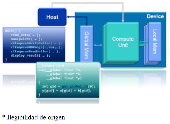
On the other hand, OpenCL (Open Computing Language) is an open standard, general-purpose programming multiplatform, which consists of a heterogenic CPU, GPU and FPGA informatics devices collection, sometimes manufactured by different suppliers; then OpenCL is a parallel-programming platform that is also portable among other advantages.
Standard OpenCL defines a datatype, data structure and functions set in languages like C and C++; OpenCL is an API (application programming interface), the code is executed in an OpenCL "Device" which is not the same device as the CPU "Host". It means it uses a processor that coordinates kernel executions (C code functions-Host side), and one or more devices able to execute the OpenCL C code (Device side).
In this work, the evaluation of a FPGA DE1_SoC as an image-processing hardware tool is presented; being OpenCL a C99 language-programming version [7], it was used as a high-level programming tool in order to accelerate the processing time for filtering application during holographic interferometry registering.
2 FPGA-OpenCL Tools
2.1 Hardware-Software
A FPGA that supports OpenCL was used as hardware; it is equipped with a Hard Processor System (HPS), which is an ARM Cortex-A9 Dual-Core at 800 MHz, 3GB DDR3 SDRAM memory; additionally contains a FPGA Cyclone V SoC from Altera family with 4,450 kb of embedded memory, 85K logical programmable elements, 64 MB off-chip SDRAM, and VGA among other elements. The software consists of OpenCL for application of image filtering and for device performance improving. The execution of an OpenCL is realized in two different ways: on one hand the Kernel program is executed in one or more OpenCL devices (Device), and on the other hand a manager program is executed in the Host (Host-program) being in this case the ARM processor of the motherboard. Host program was written in C code (programming language used in this work) and is the serial part of an application, responsible for data managing and algorithm flux controlling; the Kernel is the parallel part of the application to be accelerated on a device, as is done on a multi-core CPU, GPU or FPGA [6].
2.2 Filters
Sometimes during image acquisition process, the quality of stored images needs to be improve because of factors inherent to the process like mistakes on sensors, imperfections on optical lenses or bad focusing among others.
That is why is convenient to highlight some of the graphic information and so a pre-processing, which consists of an optimization of the image before the definitive processing, becomes necessary. Image improvement ways may be divided in two big categories: spatial domain methods and frequency domain methods.
The term "spatial domain" refers to the same image plane and is based on direct manipulation of pixels of the image; the spatial filtering is used for noise suppressing or image smoothing.
Frequency domain techniques are based on Fourier Transform modification of an image; a Bilateral Filter is an advanced one that preserves the borders of the image: the value of a pixel is calculated on a weighted average of neighborhood pixels with similar values. On more uniform regions, neighborhood pixels are similar among them and the filter acts eliminating small differences given by noise; when the central pixel is located in a dark-bright zone border, the filter replaces its value for the bright-pixels average, discarding the dark ones. In other words, when fixes in a dark pixel, the dark are averaged and the bright ones are discarded. Such procedure allows keeping the borders.
One of the most elemental ways to remove noise is by a Gaussian convolution, which is the fundamental concept for a Bilateral Filter; an image filtered by Gaussian convolution is given by:
Where
Here the W p term is a normalization factor to assure that weighted average of pixels is equal to 1 inside the window, [I] P is the value of image at position p, the parameters σ s and σ r specify the filtering quantity for the image.
Equation 3 represents a normalized weighted average, where G σs is a special Gaussian weighting that diminishes the influence of distant pixels, a Gaussian rate to low influence of q pixels when their intensity values differ from I p [8,9].
The Fourier Transform is a process that picks data samples and generates its frequency content; the output of Fourier Transform contains all of its input. A process known as the Inverse Fourier Transform may be used to recover the original signal, is a common one process used in several fields and is wide used in many programs where this procedure works as an equalizer, a filter, a compressor, etc. The Fourier Transform (u) for a single variable continuous function (x), is defined as:
where
Although this formula allows to process O digital data, with an N finite sample number, there is a disadvantage in this method because, as the number of (N 2 ) points increases, the processing time is also increased to a power of 2. For this reason, an alternative process known as the discrete Fourier Transform (DFT) was developed to estimate the Fourier Transform. The Cooley-Tukey algorithm takes advantage of the cyclic nature of Fourier Transform and solve the problem with (NlogN), by dividing DFT in smaller DFT's. The nucleus on this Fast Fourier Transform (FFT) consists of the "butterfly operation"; the operation is realized on a pair of data samples each time, which flux graphic is given in Fig. 2. The name of this operation is given because each segment looks like a butterfly.

The basic FFT algorithm is performed on one-dimension data. To obtain the FFT of an image, a FFT for a row and a column is taken. Then the FFT is first calculated for each row, this is transposed and a FFT is calculated again for such result. This is done to get a faster access to the memory, as the data are stored on the main row. If transposition is not done, an alternated memory access is produced which lows performance rate considerably as the image size increases. Once the Fourier Transform F(x,y) of image f(x,y) is obtained, it will be multiplied by a H(u,v) filter (a mask which may be used as a high-pass or low-pass filter); in such a way we will obtain a g(x,y) function (Fig. 3) [10-11].
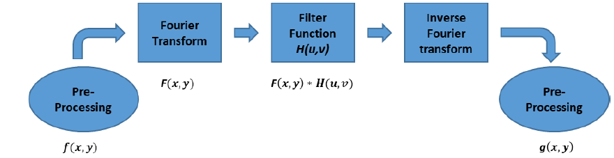
As a result we obtain F-1(x,y)=F(x,y)*H(u,v), which is the Inverse Fourier Transform calculated for final function g(x,y).
2.3 Phase Unwrapping
A conventional optical holographic interferogram can be obtained by a method commonly known as Holographic Interferometry (HI); the interferogram is generated by superposition of two coherent waves, which have been dispersed from an object previously illuminated by a coherent light beam (i.e. a laser beam). Such an object may be subjected for two different physical states, and two subsequent interferograms can be obtained for each state [12]. An interferogram carries information about phase change between the waves in the form of dark and bright fringes. The interference phase Δφ is usually calculated from three or more interferograms with a phase-shift among them. Determination of the phase is the key of HI because any information about the physical change to be measured (mechanical thickness or deformation, pressure, temperature, density, etc.) is contained into Δφ.
For this purpose, a standard algorithm developed for conventional HI or similar methods (like Electronic Speckle Pattern Interferometry) can be applied:
which is the general formula for the optical interference pattern intensity I(x,y). Next step consists on determination of phase Δφ. For 4 different captures (i.e. images) with a common π/2 phase-shift from each other (externally induced during the process), corresponding interference intensities are:
From these registers, the corresponding phase is calculated as:
At this point one detail must be considered which is the fact that, for periodic functions as sines or cosines, the calculated phase distribution is not defined for 2π additive integers as can be seen in next example:
which means that every phase distribution calculated with inverse trigonometric functions like arc tan, contains 2π jumps in such positions where extreme Δφ values of -π or π can be obtained; then calculated phase along a line taken on its corresponding image will look similar to a sawtooth function (Fig. 4a).

Fig. 4 Phase unwrapping; a) wrapped phase or interference phase in 2π modules (Δφ 2π (x)); b) step function (Δφ jump (x)); c) unwrapped interference phase (Δφ 2π (x)+Δφ jump (x))
Any method introduced for these 2π phase jumps correction is denominated demodulation, continuity or more commonly, phase unwrapping [12]; the correction of such 2π jumps must introduced a continuous phase distribution. Phase unwrapping is a special topic on optical interferometry and related methods and then several different unwrapping algorithms have been developed for such purpose.
Here we will only refer to the so called path-dependent unwrapping algorithm [12]; first a one-dimensional interference phase distribution is considered where difference between adjacent pixel phase values DIFF=Δ(n+1)-Δφ(n) is calculated.
If DIFF<-π, all phase values from (n+1) pixel and so forth are increased in 2π; however if DIFF>+π, 2π is subtracted from all phase values starting at number n+1. If any of these conditions is valid, phase value does not change. Practical implementation of this procedure is firstly realized calculating a step function, which accumulates all the 2π jumps for every pixel (Fig. 4b).
The continuous phase distribution is thereupon calculated adding the step function to the unwrapped phase distribution (Fig. 4c). Such a one-dimensional unwrapping scheme may be transferred for two-dimensions; one possibility is firstly to unwrap a row of the two-dimensional with the algorithm previously described. The pixels of this unwrap row can be considered now as starting points for subsequent columns unwrapping, that is, unwrapping begins by rows, an inverse operation on these values is applied, columns will become files and finally unwrapping will be applied on these last values. The unwrapping procedure is always the same for all metrology methods that generates saw-tooth images [12].
3 Results
Although HI holograms can be processed to obtain the interference phase by means of the phase-shift method, sometimes resulting interference phase images were noisy due to several factors during their capture, and so two filtering methods, Bilateral Filter [9] and Fourier Transform [11] were applied on 1024x1024 pixels images, which is the first goal of our work.
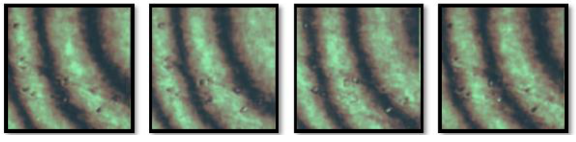
As a first step we are presenting results obtain by filtering; we have four images obtained by HI, each of 24 bits and 499x499 pixels that were loaded on the FPGA (Fig. 5). Then the phase-shift algorithm written in C language, which works linearly on each row pixels, was used to obtain the wrapped and unwrapped phase which corresponding images are shown on Fig. 6.
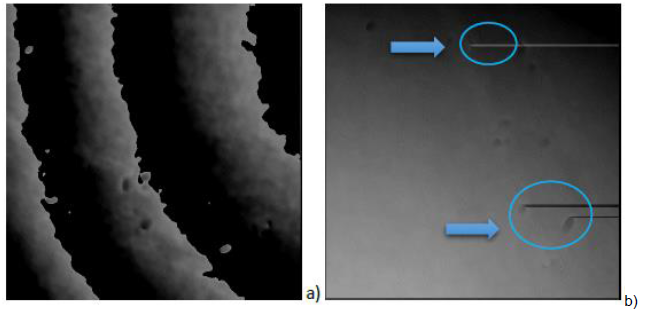
Now, in order to remove the mistakes clearly shown on Fig. 6b, the Bilateral Filter algorithm that has been proved with OpenCL, is applied for each image obtained by HI (Fig. 5). After three iterations and using a 5-window size and a σ sigma value of 0.0025, we obtain the unwrapped phase of Fig. 7.

In the same way, the Fourier Transform algorithm was tested in OpenCL on four 24 bits RGB, 1024x1024 pixels HI holograms images (Fig. 8), to obtain their corresponding wrapped and unwrapped phase (Fig. 9). For the second goal of our work, once the algorithms were checked, we proceeded to evaluate unwrap time, i.e. the time each algorithm takes to obtain an unwrapped phase image from four test images. The phase-shift and filtering algorithms were combined with the filtering algorithm in order to calculate times, accordingly with the number of iterations that can be applied to get a suitable unwrapped phase; this depends on the quantity of noise on each HI holograms. The results are summarized in the table 1.
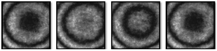
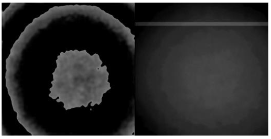
Table 1 Quantity of noise on each HI holograms
| Time (sec) | 1 iteration | 5 iteration |
|---|---|---|
| image 256x256 | image 256x256 | |
| Unwrapped phase ARM | 0.162 | 0.676 |
| Unwrapped Phase ARM Bilateral Filter | 9.818 | 47.409 |
| Unwrapped Phase FPGA OpenCL Bilateral Filter | 2.053 | 10.271 |
| image 499x499 | image 499x499 | |
| Unwrapped Phase ARM | 0.636 | 2.649 |
| Unwrapped Phase ARM Bilateral Filter | 36.756 | 182.758 |
| Unwrapped Phase FPGA OpenCL Bilateral Filter | 3.838 | 11.856 |
| image 1024x1024 | image 1024x1024 | |
| Unwrapped phase ARM | 2.6 | 10.841 |
| Unwrapped Phase ARM Bilateral Filter | 152.158 | 752.839 |
| Unwrapped Phase FPGA OpenCL Bilateral Filter | 7.702 | 49.369 |
| Unwrapped Phase FPGA OpenCL Fourier Filter | 11.816 | NULL |
As is exposed on the table above, we found that for 256x256, 499x499 and 1024x1024 pixels images with 1 and 5 computing iterations each case, times are always fast enough for unwrapping processes directly executed by the ARM processor of the motherboard, without any filtering applied but with consequent phase unwrapping mistakes.
Now when filtering procedures are introduced for 256x256 pixels images phase unwrapping we found how by using the Bilateral Filter programmed with OpenCL, processing time can be improved by a factor of 4.78 for 1 iteration and 4.6 for 5 iterations, than when Bilateral Filter programmed in C language is used. Processing times can be decreased when bigger images are considered: 499x499 pixels images gave time improving factors of 9.57 for 1 iteration and 15.4 for 5 iterations using OpenCL Bilateral Filter instead of C Bilateral Filter. Finally, for 1024x1024 pixels images, time improving factors were improved to 19.7 for 1 iteration and 15.2 for 5 iterations using OpenCL Bilateral Filter instead of the C Bilateral Filter. When Fourier Transform Filter was tested, we found that it reaches a time improving factor of 12.8 for 1 iteration with respect to the C Bilateral Filter, but we also found that Fourier Filter is slower than OpenCL Bilateral Filter by a factor of 1.5.
4 Conclusions
As can be seen, accordingly with rate performance using a FPGA programmed by using OpenCL presents a good response to the processing of multiple floating-point data series which considers the Bilateral Filter as same as the Fourier Transform Filter. It have been shown that for the case of phase unwrapping with Bilateral filtering in Open CL, rate performance is 19.7 times faster on FPGA with the ARM processor, and 12.8 times faster using Fourier Transform filtering if we consider phase unwrapping with ARM and Bilateral filtering as a reference.
Finally, we may append that evaluation of DE1-SoC FPGA board shown favorable results related with processing performance as compared with the ARM processor; additionally this procedure may be considered as a practical tool for HI with phase-shift and other related methods.

