


Servicios Personalizados
Revista
Articulo
 Inglés (pdf)
 Artículo en XML
 Referencias del artículo
 Enviar artículo por email
Indicadores
-
 Citado por SciELO
 -
 Accesos
Links relacionados
-
 Similares en
SciELO
Similares en
SciELO
Compartir

 Permalink
Boletín de la Sociedad Geológica Mexicana
versión impresa ISSN 1405-3322
Bol. Soc. Geol. Mex vol.67 no.3 Ciudad de México dic. 2015
Artículos
A concise synchrotron X-ray microdiffraction field guide for the Earth scientists
Una concisa guía de campo sobre microdifracción de rayos-X sincrotrónica para geocientíficos
Nobumichi Tamura1,* and Martin Kunz1
1 Lawrence Berkeley National Laboratory, 1 Cyclotron Road, Berkeley CA 94720, USA. * ntamura@lbl.gov
Manuscript received: October 30, 2014.
Corrected manuscript received: May 12, 2015.
Manuscript accepted: May 15, 2015.
Abstract
Most geological samples are intrinsically heterogeneous at the micron scale making their quantitative study with conventional laboratory techniques challenging. The use of synchrotron radiation, which provides high quality data with unprecedented spatial and angular resolution, has become quite ubiquitous in many branches of experimental sciences, and geology, geochemistry, Earth and environmental sciences are no exception. The present chapter offers an overview of what can be measured using synchrotron X-ray microdiffraction using an X-ray beam size in the range between 100 nm to a few microns. Experiments using geological samples are described. Two techniques, their strengths and limitations, are emphasized: powder microdiffraction and Laue microdiffraction.
Keywords: X-ray microdiffraction, synchrotron, Laue diffraction, powder diffraction, stress, microstructure.
Resumen
La mayoría de las muestras geológicas son intrínsecamente heterogéneas en la escala del micrón, lo que convierte a su estudio cuantitativo realizado con técnicas de laboratorio convencionales en algo desafiante. El uso de radiación sincrotrón, que proporciona datos de calidad con una resolución espacial y angular sin precedentes, se ha convertido en ubicua en varias de las ramas de las ciencias experimentales, y la geología, la geoquímica, las ciencias de la Tierra y las ciencias del medio ambiente no son una excepción. El presente capítulo ofrece una visión general de lo que puede ser medido utilizando microdifracción de rayos X en sincrotrón, con el tamaño de haz de rayos X en el intervalo entre 100 nm y unas pocas micras. En el presente trabajo se describen los experimentos utilizando muestras geológicas. Se enfatizan dos técnicas, sus fortalezas y limitaciones: microdifracción de polvo y microdifracción Laue.
Palabras clave: microdifracción de rayos X, sincrotrón, difracción Laue, difracción de polvo, estrés, microestructura.
1. Introduction
Natural samples often exhibit higher levels of heterogeneity than manufactured materials and therefore their microstructure, chemical and crystalline phase distribution and level of deformation are often more challenging to characterize in a quantitative way. A piece of rock, a piece of meteorite, a sample of soil, when looked under a microscope generally appear as agglomerates of multiple crystalline and non-crystalline phases with varying compositions, impurities and defect contents, structures and different grain sizes. Deciphering the particular history of a sample, such as how a particular meteorite has formed or how much stress a particular piece of rock near an earthquake fault has experienced over time, requires a thorough understanding of the microstructure. A probe is needed, capable of providing as much information as possible at the relevant length scale (typically from a few microns down to a few nanometers). Moreover, the interpretation of some measurements, such as the crystalline phase distribution resulting from a transition between two states, requires that the probe perform the measurement without destroying the sample.
Among the arsenal of characterization tools available today at synchrotron facilities, techniques such as absorption spectroscopy, including XANES (X-ray Absorption Near Edge Structure), EXAFS (Extended X-ray absorption fine structure), X-ray fluorescence, high resolution powder diffraction, SAXS (Small Angle X-ray scattering), X-ray imaging such as STXM (Scanning Transmission X-ray Microscopy) and X-ray Tomography, are increasingly used by the Earth Science community. In particular, synchrotron microfocus techniques such as X-ray microdiffraction, µSAXS, X-ray microfluorescence (µXRF), µXANES and µEXAFS, which add high spatial resolution, have become increasingly attractive as effective in situcharacterization tools. The intrinsic high brightness and collimation of X-ray beams produced at synchrotron facilities around the world make possible the routine generation of very small but intense micron to submicron size X-ray beams ideally suited to probe sample heterogeneity at this length scale. Synchrotron facilities such as the Advanced Light Source (ALS) in Berkeley, CA, the Advanced Photon Source (APS) at Argonne, IL, the European Synchrotron Research Facility (ESRF) in Grenoble, France or the 8 GeV Super Photon Ring (Spring-8) in Hyogo, Japan are very large machines financed, built and maintained to the greater part by government agencies for the benefit of academics and industries to perform experiments that generally cannot be conducted anywhere else. The electron storage rings at the core of synchrotron facilities deliver X-rays to some 20 to 40 "beamlines", each specialized in a few specific techniques. Experiment time, also known as "beamtime", is allocated to users based on scientific merit through a peer review system. Access to most synchrotron facilities is free and the cost of using such facilities generally amount only to travel cost. As demand is generally high and therefore the amount of allocated beamtime scarce, for maximum efficiency of beamtime it is imperative that each experiment be planned carefully in collaboration with the beamline personnel. Multiple techniques over several beamlines, sometimes across a few facilities, are generally applied in succession to answer a particular question about a sample. For instance, elemental distribution can be obtained by scanning X-ray microfluorescence, while X-ray microdiffraction would be used to identify the structure or determine the crystallinity of particular phases. µXANES is typically used for finding the degree of oxidation of particular elements while µEXAFS can help identify semi-amorphous materials. X-ray microtomography would be used as a 3D imaging tool based on absorption contrast. The present review will focus on synchrotron X-ray microdiffraction (also called micro X-ray diffraction or µXRD). Following a brief description of the instrumentation, the review will show how such a beamline can be used effectively to solve many problems that are relevant to geochemists, earth scientists and geologists.
2. The X-ray microdiffraction toolkit
X-ray microdiffraction is in essence the century old X-ray diffraction technique optimized to the best of today's technology in terms of X-ray focus, with, however, a few caveats. Producing a very small X-ray beam comes at a cost, but starting with high photon counts and very small beam divergence is certainly helpful in achieving this goal. This is why X-ray microdiffraction with a beam size in the order of a micron or below only appeared feasible at 3rd generation synchrotron sources. Progress in X-ray focusing technologies combined with efficient vibration damping systems allow today for an X-ray beam in the order of a few tens of nanometers in size, but more routinely in a micron size range. All X-ray focusing optics are based on one, sometimes two, of the three following physical phenomena arising when a wave of X-rays encounter solid material: diffraction, total external reflection and refraction. They are therefore often classified into diffractive, reflective and refractive optics. Fresnel zone plates (or simply zone plates, ZPs) are examples of diffractive optics, consisting of concentric rings of alternating X-ray transparent and opaque material with widths inversely proportional to the radius of the ring. Their intrinsic chromaticity (focal length depends on X-ray wavelength) restrict their use to monochromatic applications. A focus size in the range of 10 nm has been achieved (Chao et al., 2005) and zone plates are therefore highly popular with "soft" and "tender" (energy below 10 keV) X-ray microscopy (Kirz et al., 1995; Larabell and Le Gros, 2004). For hard X-rays, zone plates need to be thick enough for absorption in the opaque regions to be effective, but high aspect ratio rings are quite challenging to manufacture (Feng et al., 2007a; Chu et al., 2008) and therefore zone plates are often replaced by other optics for X-ray above 10 keV. X-ray mirrors, consisting of a metal coating on top of a rigid substrate, use total external reflection to deflect the X-ray beam path. Bent to an elliptical profile, an X-ray mirror can be used to focus the beam in one direction. Kirkpatrick-Baez (KB) mirrors consist of an orthogonal pair of elliptically shaped mirrors to focus a beam in two directions (Kirkpatrick and Baez, 1948). Spot sizes of a few tens of nanometers have been achieved in the last decade with ultrasmooth KB mirrors (Mimura et al., 2005). KB mirrors offer the advantages of high efficiency and relatively high acceptance, making them ideal for "hard" X-ray (energy above 10 keV) applications. Since they are achromatic, they are the tool of choice for polychromatic and spectroscopic applications. Compound refractive lenses (CRLs) consist of a series of concave lenses carved out of light elements that are an alternate low-cost hard X-ray focusing optics (Snigirev et al., 1998; Schroer et al., 2003). CRLs are, however, highly achromatic and work for monochromatic beams only. Currently, ZPs, KBs and CRLs are the three most widely used X-ray focusing optics at synchrotrons. However, there are many other concepts that have been developed such as X-ray waveguides (Jark et al., 2001), Bragg-Fresnel lenses (Aristov et al., 1989), kinoform lenses (Evans-Lutterodt et al., 2007), X-ray capillaries (Bilderback, 2003) and prism array lenses (Jark et al., 2004).
For medium angular resolution measurements, the X-ray diffraction detectors of choice today are two dimensional area detectors that output diffraction patterns in easy-to-handle digital format. Examples of 2D detectors include X-ray charge coupled devices (CCDs), pixel array detectors and image plates. They come in increasingly larger sizes, number of pixels and speed and can capture in a single shot a large angular portion of the reciprocal space, making experiments much faster as the detector remains stationary throughout the duration of the measurement (Tate et al., 1995; Broennimann et al., 2006).
Many beamlines around the world offer microdiffraction capabilities, but only a few are fully dedicated stations. One such example is given by BL12.3.2 at the Advanced Light Source (Kunz et al., 2009b; Tamura et al., 2009). The outline of this beamline is shown in Figure 1. The source is a superconducting bending magnet that provides X-rays with a critical energy around 12 keV, i.e., well into the hard X-ray regime. A toroidal mirror refocuses the beam onto the entrance of the experimental hutch where a pair of slits are used as a virtual secondary source that is size adjustable. Final focusing is provided by a pair of elliptically bent KB mirrors with tungsten coating working at a nominal incidence angle of 3.5 mrad (Yashchuk et al., 2013). Nominal X-ray beam size on the sample is about 1 µm by 1 µm. A four-bounce constant-exit monochromator consisting of two identical channel-cut Si(111) crystals can be inserted in the path of the beam for an easy and rapid switch between polychromatic (white) beam and monochromatic beam, while illuminating the same spot on the sample. This is one capability which is rather unique to BL12.3.2, the possibility to conduct both white and monochromatic X-ray experiments on the same micron area of the sample (Dejoie et al., 2015). The available photon energy range is between 5 and 24 keV. The sample sits on a flexible xyzχϕ stage. X-ray diffraction patterns are collected using a DECTRIS Pilatus 1M hybrid pixel array detector, while X-ray fluorescence spectra can be collected with a VORTEX EM silicon drift detector. More technical details about the beamline can be found in Kunz et al., 2009b.
Besides ALS BL12.3.2, we can cite the APS undulator beamline 34 ID-E (Ice et al., 2005) specialized into a depth resolved technique called Differential Aperture X-ray Microscopy (DAXM), which uses polychromatic or monochromatic beam and a scanning wire near the surface of the sample to ray trace the reflections along the penetration depth of the beam into the sample (Larson et al., 2002). DAXM is one of the so-called 3D X-ray microdiffraction techniques that can reconstruct the volumetric distribution of grains and strains with submicron resolution. The VESPERS beamline at the Canadian Light Source (Feng et al., 2007b) and BM32 at the ESRF (Ulrich et al., 2011) offer capabilities similar to the ALS beamline. Undulator beamlines such as the 2-ID-D at the APS (Cai et al., 2000) and the Microfocus beamline ID 13 at the ESRF (Engström et al., 1995) provide monochromatic X-ray diffraction with high spatial resolution on the order of a few tens of nanometers. The ESRF Materials Science beamline ID11 offers a wide range of monochromatic diffraction techniques including 3D X-ray Diffraction (3DXRD), which is capable of mapping grains in 3D in deformed materials (Poulsen et al., 2001). The ESRF Microdiffraction Imaging beamline ID01 provides a submicron monochromatic beam for the study of engineered materials (Diaz et al., 2009), and the High Energy Scattering beamline ID15 has a high energy microdiffraction (HEMD) setup. Microspectroscopy beamlines such as the ALS BL10.3.2 often offer powder microdiffraction capability as well. For historical reasons, we also want to mention the now decommissioned NSLS X26C beamline (Wang et al., 1998) where some of the very first synchrotron microdiffraction experiments were performed with a 10 µm size white beam, as well as X26A (Lanzirotti et al., 2010) and X27A (Ablett et al., 2006) environmental science beamlines at NSLS.
Note that the X-ray photon flux (number of photons per second) reaching the sample, even with today's 3rdgeneration synchrotron sources, is still often a limiting factor for micro- and nano-focus applications, especially when a monochromatic beam is used. This is particularly true for the often weakly scattering environmental and geological samples where better signal-to-noise ratio and better diffracted intensity are needed. To that effect, several synchrotron facilities such as the ESRF, Spring8, APS and ALS are undertaking upgrades for smaller electron beam emittance to provide more photon flux and beam coherence.
Targeting a small micron-sized X-ray beam onto a specific small micron-sized area on the sample is difficult, so an efficient navigation system towards the point of interest has to be devised. This is generally provided by combining a good optical viewing system aimed at the sample and carefully calibrated to the focal point of the X-ray beam, and markings on the sample that are visible to X-rays, such as platinum marks deposited by Focused Ion Beam (FIB) that can be easily found by monitoring X-ray fluorescence. One caveat of microdiffraction is that sample rotation is generally to be avoided when the feature of interest is in the same order of size as the beam. Even the best diffractometer comes with a "sphere of confusion" exceeding today's small beam sizes, which therefore moves the sample out of the beam during rotation (Noyan et al., 1999). Moreover, X-ray penetration also makes the volume of diffraction change with each angle, resulting in systematic errors when comparing reflections taken at different angles (Ice et al., 2000). This is why some methods used in X-ray microdiffraction differ from conventional ones used for regular "macroscopic" X-ray diffraction. Avoiding rotation in microdiffraction has been the driving force to seek alternate solutions to standard single crystal diffraction techniques for structure solution, reciprocal space mapping and residual stress measurement. Although the results may not always be as satisfying as those obtained by the well-established macroscopic techniques, these alternate methods offer the advantage of speed, as rotation is time consuming and not well suited for time resolved experiments. Besides, some samples, such as a precious small mineral embedded in a heterogeneous matrix or a high pressure compound inside a diamond anvil cell (DAC), are not suited to be freely rotated under the beam and the use of one of these alternate methods could be the only way to get around the limitation. Two methods, namely polychromatic X-ray microdiffraction and powder X-ray microdiffraction, are discussed in details in the following sections.
3. Sample preparation
Hard X-rays are penetrating, providing an advantage over electron microscopy or soft X-rays when it comes to sample preparation and sample environment. Sample preparation can be kept to a minimum and measurements performed in air (unless oxidation becomes an issue). This is particularly attractive for cases where the sample is buried inside a matrix or confined in a pressure chamber such as a DAC. A reasonably flat surface obtained through regular polishing is often all that is required for an experiment in reflective geometry. It is important, however, to complement mechanical polishing with chemical or electrochemical polishing for samples that are subject to mechanical deformation, such as metals and alloys, to remove the damaged surface layers. A note of caution, however, shall be given as X-ray penetration can also work against you if one is not careful; make sure that the sample is not too thick or that there is nothing underneath the sample that can diffract equally well. The superimposition of multiple diffraction patterns coming from different layers beneath the surface may become very difficult to interpret. If using a thin section on a glass slide, note that the slide itself would produce a contribution in the shape of a broad diffraction ring in monochromatic mode (Gräfe et al., 2014) and a large scattering background signal in polychromatic mode. These parasitic contributions can generally be digitally subtracted from the diffraction patterns, but may, however, become overwhelmingly high for weakly scattering samples. For transmission experiments, the thickness of the sample to use is determined by the average atomic number of the compound to be measured, but 20 – 40 µm is a good number for most geological samples.
4. Powder microdiffraction
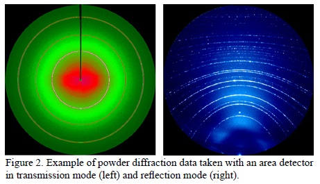
Powder microdiffraction is the technique of choice for polycrystalline samples when the average size of crystallites or coherently diffracting units in the sample is much smaller than the X-ray beam size illuminating them (for a micron size X-ray beam, this means crystallite size of less than 100 nm). This is almost always the case for soil samples, and the fine fraction of industrial residues. When a monochromatic beam with a selected wavelength hits the sample, cones of diffraction specific to particular hkl crystallographic planes are formed and intersect the plane of the 2D detector as a portion of conics. The shape of the conics in the resulting diffraction pattern depends on the position and angle of the detector relative to the incident beam. It can be circular (direct transmission geometry), elliptic, parabolic or hyperbolic (Figure 2). The resulting diffraction patterns are called 2D powder patterns or Debye-Scherrer ring patterns. The angular positions and relative intensities of the rings are characteristics of the crystal structure of the diffracting materials and can be used for identifying the phases present in the sample. The common analytical practice is to integrate the 2D pattern along the azimuthal (χ) direction to form a 1D diffractogram that can be easily plugged into a database to search for matching crystal structures. The advantage of using a small beam becomes evident when a heterogeneous sample is considered. With a larger beam and such a sample, it can indeed become very difficult to disentangle reflections from a dozen different phases when there are many peaks overlapping and when some of the intensities are modified by texture.
Since most of the rings that help to unambiguously identify a crystalline structure occur at low angle, powder microdiffraction is generally best performed with the detector placed at a low 2θ angle, preferentially in transmission geometry, if the sample is thin enough. Poorly crystallized phases, such as clays, exemplify this very well as rings are broadened by the very small size of the constitutive crystallites; high angle rings have not only weakened intensities due to the decreasing form factor, but being more numerous, are also subject to strong overlaps. Clays are often identified by their lowermost angle of reflection. For example, for that of kaolinite and nontronite, 2θ = 9.2 and 4.6°, respectively, at 10 keV. For thicker samples, the sample surface will need to be put at a very shallow angle with respect to the incoming beam, which results in loss of spatial resolution in one direction as the beam footprint on the sample increases.
Reducing 2D patterns into 1D diffractograms is not always helpful, as much information about texture, crystal size and strain may be lost this way and is then difficult to retrieve in the final spectrum. The uneven intensity distribution along the azimuthal directions of diffraction rings reflects preferential orientation or texture, for instance. Highly textured samples show incomplete rings in the form of arcs that can be interpreted into pole figures. The level of graininess of the rings along the azimuthal direction is also a good qualitative indication of grain size. For a micron-sized beam, spotted rings are characteristics of samples with an average grain size that are about an order of magnitude smaller than the beam, while continuous rings indicate grain sizes two or more orders of magnitude smaller. In the latter case, the width of the rings in the radial direction is inversely proportional to the grain size, according to the Scherrer equation (Patterson, 1939). Perhaps a little less relevant for geological or environmental samples, mechanically or chemically induced strain can, in principle, be measured by powder microdiffraction. The standard distinction between "microstrain" and "macrostrain" is somewhat arbitrary, but as a rule of thumb, microstrain refers to strain distributions that vary within the X-ray illuminated area, which would cause a spread of interatomic spacings of hkl planes, resulting in a broadening of the rings associated to those planes. Formula such as the one provided by the Stokes-Wilson equation (Stokes and Wilson, 1944) can then be used to assess microstrain. Macrostrain, on the other hand, refers to a deformation which is uniform within the X-ray illuminated area. Such strain does not affect the broadening of the rings but their ellipticity. By fitting the shapes of multiple rings to a generalized sin2 ψ equation, it is possible to derive the entire strain tensor of the crystal (Noyan and Cohen, 1987; Tamura, 2014). Finally, Rietveld refinement (Rietveld, 1969; McCusker et al., 1999) is a technique developed to refine the crystal structure of unknown compounds through a high resolution powder X-ray diffractogram (although originally formulated for neutron diffractograms). Note that Rietveld refinement could become quite problematic if not all reflections of the material are visible because of angular constraints or preferred orientation (texture). This well-established technique can be used for a wide variety of refinement such as size and strain distribution (Lutterotti and Scardi, 1990; Balzar and Popa, 2005) and texture (Popa, 1992; von Dreele, 1997).
A large variety of software exists to handle powder X-ray diffraction data obtained with an area detector, and can readily be used to treat powder microdiffraction data. Fit2D has been a pioneer in that area and was for a while the most widely used code for transmission geometry (Hammersley, 1996). The package contains all the standard tools such as distance calibration, center determination, intensity integration and peak fitting that have been adopted in all subsequent software. The Windows-based application XRD2DScan provides hands-on routines for determining average crystal size and quantification of preferential orientation (Rodriguez-Navarro, 2006) and can batch-process file series. XRDUA (De Nolf et al., 2014) is relatively new software that can also process diffraction tomography data. MAUD (Lutterotti et al., 1999) specializes in texture analysis via Rietveld refinement. XMAS (X-ray Microdiffraction Analysis Software) developed at the ALS (Tamura, 2014) can process data taken in both transmission and reflection geometries and can process raster scans into maps. Let's also mention XPLOT2D of the XOP package (Sanchez del Rio and Dejus, 2004) and PyFAI (Kieffer and Karkoulis, 2013), both designed for performing azimuthal integrations of 2D detector data. Companies selling 2D X-ray detectors sometimes provide their own suite of software such as GADDS developed by Bruker AXS Inc. (Rowe, 2009). This list is in no way complete.
Powder microdiffraction has been widely used to identify minority phases in a wide range of geological samples. Some examples include speciation studies in ferromanganese nodules (Manceau et al., 2002), identification of interplanetary particles from the STARDUST mission (Nakamura et al., 2008), the study of acid mine drainage (Soler et al., 2008; Courtin-Nomade et al., 2012) or establishing the phase distribution at a heterogeneous cement-clay interface (Dähn et al., 2014). With regard to powder diffraction in general, we would like to stress the importance of crystallographic databases for phase identification. The International Centre for Diffraction Data (ICDD) has the most comprehensive database of inorganic compounds, but it is quite expensive and not always available at the institution hosting the beamline. Free but less complete databases available online includes the Crystallography Open Database (COD) (http://www.crystallography.net), the RRUFF project (http://rruff.info) and MINCRYST (http://database.iem.ac.ru/mincryst/).
Used in scanning mode, powder microdiffraction becomes an effective way to map phase distribution in a heterogeneous rock. Typical examples for very fine-scaled heterogeneous rocks can be found in partially weathered mine tailings, whose composition and evolution is of considerable interest since they pose a significant hazard to the environment due to their potential for toxic element release. To understand the processes occurring in acid mine tailings during exposure to atmospheric conditions, a detailed description, not only of the chemical composition but also of their mineralogical phase distribution on multiple scales from µm to km is required. A particular concern is the mobilization and transport of arsenic, which is present at toxic concentrations in tailings, where metals were mined in sulfide ore bodies. In an example from two former mines (gold and tungsten) in France (Courtin-Nomade et al., 2012), micro-spectroscopy is combined with powder microdiffraction to unravel the pH dependent dissolution and precipitation behavior of As. Combining chemical maps with powder microdiffraction-derived phase maps allows researchers to follow the speciation of As in different pH environment (Figure 3).
The possibility to mount thin sections of samples in transmission geometry and probe them with a small monochromatic beam also allows researchers to test in situ the spatial variation of texture. This has been nicely shown for authigenically grown ettringite in microscopic veins (Figure 4a) within decaying concrete (Wenk et al., 2009). The diffraction pattern in Figure 4b shows strong preferred orientation as evidenced by the significant azimuthal intensity variations. These intensity variations can be converted into pole figures and inverse pole figures, revealing a strong fiber texture with the c-axis perpendicular to the crack surface. This is interesting since ettringite (trigonal structure, space group P31c, a = 11.23 Å, c = 21.44 Å) exhibits the strongest stiffness parallel to c as opposed to another frequent secondary crack filling mineral phase, portlandite, Ca(OH)2, which grows with its softest direction perpendicular to the crack surfaces.

5. Polychromatic (Laue) microdiffraction
When crystallite sizes are in the order of magnitude of the X-ray beam size, monochromatic beam diffraction becomes challenging because of the necessity to bring sets of hkl planes into Bragg conditions. To that effect, sample rotation is a possibility if using a medium-sized beam (a few microns) large enough to accommodate sample motions during rotation. Single crystal diffraction conditions may be achieved this way; however, as noted in the introduction, the crystallite of interest would first need to be extracted first from the matrix. Another possibility is to reproduce a powder pattern. This method is more generally applied to polycrystalline samples where sample displacements become an ally rather than a hindrance; as many different crystals come into diffraction while rotating the sample, a powder pattern is generated and analytical methods described in section 3 can be applied. Raster scanning the polycrystalline sample is another solution to produce powder diffraction conditions, but this comes at the expense of spatial resolution. A better and less time consuming way to circumvent sample rotation is to use a polychromatic instead of monochromatic X-ray beam, simultaneously satisfying the Bragg condition for a number of reflections. The resulting diffraction pattern is called a Laue pattern (Figure 5). Since a single shot is all that is needed to obtain a Laue pattern, polychromatic microdiffraction is very fast and is suitable not only for samples having crystallite size larger than the beam size but also for time resolved studies. The interpretation of such patterns is usually not as easy; indexing requires matching a number of angles between reflections within the Laue pattern with those theoretically calculated for a given structure (Wenk et al., 1997). As the wavelength of each reflection is not known a priorifrom the Laue pattern alone, interplanar spacing values cannot be associated to it simply from the position of the reflection on the detector as with monochromatic beams. Nevertheless, successful indexing of a Laue pattern not only identifies the crystalline phase (although isomorphous compounds cannot be distinguished this way) but provides the full crystallographic orientation of the crystallite with respect to an arbitrarily chosen coordinate system (usually the sample coordinate system).
Small shifts in reflection positions relative to their ideal ones, as calculated from a perfect unit cell, can also be measured and converted into the deviatoric strain tensor and therefore can be used to assess the crystallite's elastic deformation (Chung and Ice, 1999). Moreover, local lattice bendings generated by geometrically necessary dislocations will result in asymmetric broadening of the reflections. These reflections can be directly compared to simulations in order to determine such information as dislocation densities and crystallographically active slip systems (Barabash et al., 2001). This can be used to assess the local level of plastic deformation in the sample.
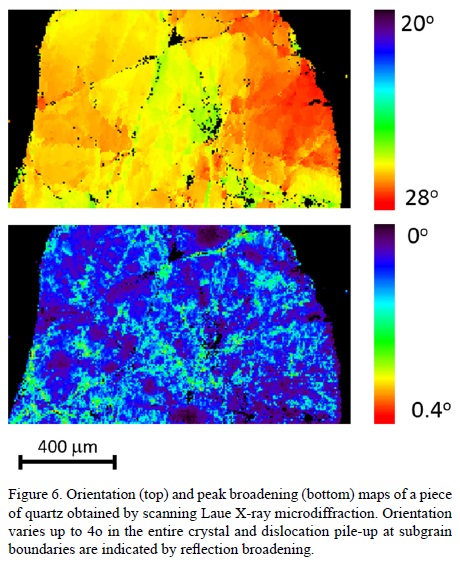
For a beamline with a maximum energy around 20 keV, Laue microdiffraction works best in reflection geometry with the detector placed at a higher 2θ angle. This stems from the fact that a sufficient number of reflections have to be visible on a diffraction pattern in order to unambiguously index it, and the population of possible reflections is denser at high angles. Indeed, most minerals have small to medium size unit cells that create only a few reflections at low angles. High energy beamlines do not have this limitation and Laue microdiffraction in that case works perfectly well in transmission geometry, but the detector has to be translated further back from the sample to preserve angular resolution. Since data collection is rather fast (second to sub second exposure time for each frame), Laue microdiffraction is often used in scanning mode. Thus, a raster scan of the sample can be used to map crystalline phase distribution, crystal orientation, as well as elastic and plastic strains. Figure 6 shows an example of such maps.
Analytical software capable of rapidly analyzing in a fully automated way tens of thousands of Laue patterns is a necessity for such experiments. The XMAS software, already cited in section 3, was originally written for that purpose. Additionally, part of its core capabilities are Laue X-ray microdiffraction patterns, reflection search and fitting, indexing and strain refinement, as well as many add-on routines for simulations and data visualization, and monochromatic beam data analysis. The open source code LaueTools developed at the ESRF (Robach et al., 2011) reproduces many of the Laue analysis functionalities of XMAS in an open source environment, providing publication ready outputs, and has lately gained increasing popularity among Laue microdiffraction users in Europe.
Synchrotron Laue microdiffraction had its initial successes in the study of the mechanical properties of functional materials and microelectronic devices (Valek et al., 2003; Rogan et al., 2003; Mehta et al., 2007), but has now expanded its range of applicability to many other scientific areas. Probably because the data interpretation is less straightforward and the methodology is less widely distributed, Laue microdiffraction has scarcely been used for geochemical and geological studies. However, recent studies show that it can be effectively employed to assess the level of stress in shocked quartz from a meteor impact site (Chen et al., 2011a) and to derive the hierarchy and sequence of mechanical twins in geological calcite, opening the prospect of using Laue microdiffraction measurements as a palaeopiezometer (Chen et al., 2011b).
A series of initial studies applying Laue X-ray microdiffraction to geological samples explored the possibilities to measure residual stresses in quartz crystals from a variety of rocks (Kunz et al., 2009a; Chen et al., 2011a). Quartz is a quite obvious choice as paleo-piezometer, since it shows very little chemical substitution giving rise to chemically induced variations in cell parameters, occurs in a wide variety of rocks and exhibits relatively high trigonal symmetry thus facilitating accurate determination of the deviatoric strain tensor. Figure 6 shows an example of high-resolution maps showing the variation in lattice orientation as well as the dislocation density within a grain of quartz from the Bergell granite intrusion. The resolution in orientation lies around 0.01°, therefore enabling the measurement of subtle changes in lattice orientations leading to undulatory extinction in quartz. The dislocation density map displays the accumulation of dislocations in the vicinity of cracks.
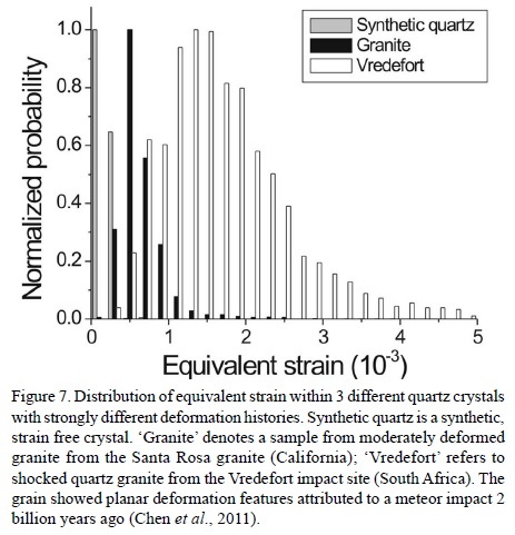
Figure 7 compares histograms of equivalent strain as defined by Liu (2005) for three different quartz crystals with different deformation histories, ranging from synthetic fully unstrained quartz to 2 billion year old quartz subject to a meteor impact. While the synthetic quartz showed no strain signal above experimentally inherent noise, the shocked crystal shows a distribution of equivalent strain values centered around 1.5 microstrains. In between these values is the strain distribution measured on a quartz crystal extracted from granite, which underwent some moderate deformation.
6. Conclusions and future perspectives
Synchrotron X-ray microdiffraction is a powerful but underutilized tool to study the microstructure of geological and environmental samples. It can be used effectively for mapping phase distribution, determining crystal structure of minute elements and measuring strain and dislocation densities. Monochromatic (powder) and polychromatic (Laue) microdiffraction can be used together in heterogeneous samples to map both nanocrystallized, or poorly crystallized, and microcrystallized phases using powder and Laue microdiffraction, respectively. For example, this combination has been exploited to maximum effect in the study of ancient ceramics (Leon et al., 2010; Dejoie et al., 2014; Dejoie et al., 2015). Initially, in an effort to avoid the sphere of confusion problem, X-ray microdiffraction experiments were confined to techniques that avoided sample rotation. However, due to developments in data reduction software, the absence of sample rotation has become the principal strength of microdiffraction. Today, area detectors work at unprecedented speed and angular resolution that take full advantage of the high photon flux provided by synchrotron beamlines (Gruner et al., 2002; Broennimann et al., 2006; Henrich et al., 2011; Ponchut et al., 2011). A full diffraction pattern can be collected in subsecond to a few seconds time with negligible instrumental downtime. This, combined with the exponential increase in computing power that we are currently experiencing, is triggering the next evolution for the X-ray microdiffraction technique that has been developed in the last decade. We are in the process of transitioning from a microstructure mapping tool where a few hundreds of diffraction patterns are obtained from a raster scan and processed off-line at the home institution of the experimenter, to a real-time microstructure imaging tool where several tens of thousands of patterns are collected in a reasonable amount of time (no more than a few hours for a few days of beamtime) and processed transparently and directly during the beamline. Codes such as XMAS have already been exported onto supercomputers allowing extraction of information such as crystal orientation and strains from thousands of patterns within minutes instead of hours, rendering the study of dynamic processes such as crack propagation within reach. Structure solution by Laue microdiffraction is another area that is benefiting geology (Dejoie et al., 2013). This might indeed be the only possible way to solve the atomic structure of tiny unknown crystals embedded in a heterogeneous, rocky matrix, or new phases generated under high pressure and temperature inside a DAC. There are, therefore, strong indications that synchrotron microdiffraction could become one of the standard techniques for the geologist and geochemist among the arsenal of already available tools such as synchrotron X-ray and Raman microspectroscopies, soft and hard X-ray imaging, and electron microscopies.
Acknowledgements
The Advanced Light Source (ALS) is supported by the Director, Office of Science, Office of Basic Energy Sciences of the U.S. Department of Energy under Contract No. DE-AC02-05CH11231 at the Lawrence Berkeley National Laboratory (LBNL). The authors would like to thank the reviewers for their useful comments on how to improve the manuscript.
References
Ablett, J.M., Kao, C.C., Reeder, R.J., Tang, Y., Lanzirotti, A., 2006, X27A—A new hard X-ray micro-spectroscopy facility at the National Synchrotron Light Source: Nuclear Instruments and Methods in Physics Research Section A: Accelerators, Spectrometers, Detectors and Associated Equipment, 562 (1), 487–494. [ Links ]
Aristov, V.V., Basov, Y.A., Kulipanov, G.N., Pindyurin, V.F., Snigirev, A.A., Sokolov, A.S., 1989, Focusing properties of a Bragg-Fresnel lens in the white spectrum of synchrotron radiation: Nuclear Instruments and Methods in Physics Research Section A: Accelerators, Spectrometers, Detectors and Associated Equipment, 274 (1–2), 390–393. [ Links ]
Balzar, D., Popa, N. C., 2005, Analyzing microstructure by Rietveld refinement: The Rigaku Journal, 22 (1), 16–25. [ Links ]
Barabash, R., Ice, G.E., Larson, B.C., Pharr, G.M., Chung, K.-S., Yang, W., 2001, White microbeam diffraction from distorted crystals: Applied Physics Letters, 79 (6), 749–751. [ Links ]
Bilderback, D.H., 2003, Review of capillary X-ray optics from the 2ndInternational Capillary Optics Meeting: X-ray Spectrometry, 32 (3), 195–207. [ Links ]
Broennimann, C., Eikenberry, E. F., Henrich, B., Horisberger, R., Huelsen, G., Pohl, E., Schmitt, B., Schulze-Briese, C., Suzuki, M., Tomizaki, T., Toyokawa, H., Wagner, A., 2006, The PILATUS 1M detector: Journal of Synchrotron Radiation, 13 (Pt 2), 120–30. [ Links ]
Cai, Z., Lai, B., Yun, W., Ilinski, P., 2000, A hard X-ray scanning microprobe for fluorescence imaging and microdiffraction at the advanced photon source: AIP Conference Proceedings, 507, 472–477. [ Links ]
Chao, W., Harteneck, B.D., Liddle, J.A., Anderson, E.H., Attwood, D.T., 2005, Soft X-ray microscopy at a spatial resolution better than 15 nm: Nature, 435 (7046), 1210–1213. [ Links ]
Chen, K., Kunz, M., Tamura, N., Wenk, H.-R., 2011a, Evidence for high stress in quartz from the impact site of Vredefort, South Africa: European Journal of Mineralogy, 23 (2), 169–178. [ Links ]
Chen, K., Kunz, M., Tamura, N., Wenk, H.-R., 2011b, Deformation twinning and residual stress in calcite studied with synchrotron polychromatic X-ray microdiffraction: Physics and Chemistry of Minerals, 38 (6), 491–500. [ Links ]
Chu, Y.S., Yi, J.M., De Carlo, F., Shen, Q., Lee, W.-K., Wu, H.J., Wang, C.L., Wang, J.Y., Liu, C.J., Wang, C.H., Wu, S.R., Chien, C.C., Hwu, Y., Tkachuk, A., Yun, W., Feser, M., Liang, K.S., Yang, C.S., Je, J.H., Margaritondo, G., 2008, Hard-X-ray microscopy with Fresnel zone plates reaches 40 nm Rayleigh resolution: Applied Physics Letters, 92 (10), 103119. [ Links ]
Chung, J., Ice, G., 1999, Automated indexing for texture and strain measurement with broad-bandpass X-ray microbeams: Journal of Applied Physics, 86 (9), 5249–5255. [ Links ]
Courtin-Nomade, A., Rakotoarisoa, O., Bril, H., Grybos, M., Forestier, L., Foucher, F., Kunz, M., 2012, Weathering of Sb-rich mining and smelting residues: Insight in solid speciation and soil bacteria toxicity: Chemie der Erde – Geochemistry, 72, 29–39. [ Links ]
Dähn, R., Popov, D., Schaub, P., Pattison, P., Grolimund, D., Mäder, U., Jenni, A., Wieland, E., 2014, X-ray micro-diffraction studies of heterogeneous interfaces between cementitious materials and geological formations: Physics and Chemistry of the Earth, Parts A/B/C, 70–71, 96–103. [ Links ]
De Nolf, W., Vanmeert, F., Janssens, K., 2014, XRDUA: crystalline phase distribution maps by two-dimensional scanning and tomographic (micro) X-ray powder diffraction: Journal of Applied Crystallography, 47 (3), 1107–1117. [ Links ]
Dejoie, C., McCusker, L.B., Baerlocher, C., Kunz, M., Tamura, N., 2013, Can Laue microdiffraction be used to solve and refine complex inorganic structures?: Journal of Applied Crystallography, 46 (6), 1805–1816. [ Links ]
Dejoie, C., Sciau, P., Li, W., Noé, L., Mehta, A., Chen, K., Luo, H., Kunz, M., Tamura, N., Liu, Z., 2014, Learning from the past: rare ε-Fe2O3in the ancient black-glazed Jian (Tenmoku) wares: Scientific Reports, 4, 4941. [ Links ]
Dejoie, C., Kunz, M., Tamura, N., Goudeau, P., Sciau, P., 2015, Complementary use of monochromatic and white-beam X-ray micro-diffraction for the investigation of ancient materials: Journal of Applied Crystallography 48 (5), 1522–1533. [ Links ]
Diaz, A., Mocuta, C., Stangl, J., Vila-Comamala, J., David, C., Metzger, T. H., Bauer, G., 2009, Spatially resolved strain within a single SiGe island investigated by X-ray scanning microdiffraction: Physica Status Solidi (a), 206 (8), 1829–1832. [ Links ]
Engström, P., Fiedler, S., Riekel, C., 1995, Microdiffraction instrumentation and experiments on the microfocus beamline at the ESRF: Review of Scientific Instruments, 66 (2), 1348. [ Links ]
Evans-Lutterodt, K., Stein, A., Ablett, J., Bozovic, N., Taylor, A., Tennant, D., 2007, Using Compound Kinoform Hard-X-ray Lenses to Exceed the Critical Angle Limit: Physical Review Letters, 99 (13), 134-801. [ Links ]
Feng, Y., Feser, M., Lyon, A., Rishton, S., Zeng, X., Chen, S., Sassolini, S., Yun, W., 2007a, Nanofabrication of high aspect ratio 24 nm X-ray zone plates for X-ray imaging applications: Journal of Vacuum Science & Technology B: Microelectronics and Nanometer Structures, 25 (6), 2004. [ Links ]
Feng, R., Gerson, A., Ice, G., Reininger, R., Yates, B., McIntyre, S., 2007b, VESPERS: A Beamline for Combined XRF and XRD Measurements: AIP Conference Proceedings, 879, 872–874. [ Links ]
Gräfe, M., Klauber, C., Gan, B., Tappero, R.V., 2014, Synchrotron X-ray microdiffraction (µXRD) in minerals and environmental research: Powder Diffraction, 29(S1), S64–S72. [ Links ]
Gruner, S.M., Tate, M.W., Eikenberry, E.F., 2002, Charge-coupled device area X-ray detectors: Review of Scientific Instruments, 73 (8), 2815. [ Links ]
Hammersley, A., 1996, Two-dimensional detector software: from real detector to idealised image or two-theta scan: High Pressure Research, 14, 235–248. [ Links ]
Henrich, B., Becker, J., Dinapoli, R., Goettlicher, P., Graafsma, H., Hirsemann, H, Klanner, R., Krueger, H., Mazzocco, R., Mozzanica, A., Perrey, H., Potdevin, G., Schmitt, B., Shi, X., Srivastava, A.K., Trunk, U., Youngman, C., 2011, The adaptive gain integrating pixel detector AGIPD a detector for the European XFEL: Nuclear Instruments and Methods in Physics Research Section A: Accelerators, Spectrometers, Detectors and Associated Equipment, 633, S11–S14. [ Links ]
Ice, G., Chung, J., Larson, B., Budai, J., Tischler, J.Z., Tamura, N., Lowe, W., 2000, Design and performance of X-ray optics optimized for polycrystalline microdiffraction: AIP Conference Proceedings, 521, 19–24. [ Links ]
Ice, G.E., Larson, B.C., Yang, W., Budai, J.D., Tischler, J.Z., Pang, J. W.L., Barabash, R.I., Liu, W., 2005, Polychromatic X-ray microdiffraction studies of mesoscale structure and dynamics: Journal of Synchrotron Radiation, 12 (Pt 2), 155–62. [ Links ]
Jark, W., Cedola, A., Di Fonzo, S., Fiordelisi, M., Lagomarsino, S., Kovalenko, N.V., Chernov, V.A., 2001, High gain beam compression in new-generation thin-film X-ray waveguides: Applied Physics Letters, 78 (9), 1192. [ Links ]
Jark, W., Pérennès, F., Matteucci, M., Mancini, L., Montanari, F., Rigon, L., Tromba, G., Somogyi, A., Tucoulou, R., Bohic, S., 2004, Focusing X-rays with simple arrays of prism-like structures: Journal of Synchrotron Radiation, 11 (Pt 3), 248–53. [ Links ]
Kieffer, J., Karkoulis, D., 2013, PyFAI, a versatile library for azimuthal regrouping: Journal of Physics: Conference Series, 425 (20), 202012. [ Links ]
Kirkpatrick, P., Baez, A.V., 1948, Formation of optical images by X-rays: Journal of the Optical Society of America, 38 (9), 766–774. [ Links ]
Kirz, J., Jacobsen, C., Howells, M., 1995, Soft X-ray microscopes and their biological applications: Quarterly Reviews of Biophysics, 28 (1), 33–130. [ Links ]
Kunz, M., Chen, K., Tamura, N., Wenk, H.-R., 2009a, Evidence for residual elastic strain in deformed natural quartz: American Mineralogist, 94 (7), 1059–1062. [ Links ]
Kunz, M., Tamura, N., Chen, K., Macdowell, A.A, Celestre, R.S., Church, M.M., Fakra, S., Domning, E.E., Glossinger, J.M., Kirshman, J.L., Morrison, G.Y., Plate, D.W., Smith, B.V., Warwick, T., Yashchuk, V.V., Padmore H.A., Ustundag, E., 2009b, A dedicated superbend X-ray microdiffraction beamline for materials, geo-, and environmental sciences at the advanced light source: The Review of Scientific Instruments, 80 (3), 035108. [ Links ]
Lanzirotti, A., Tappero, R., Schulze, D.G., 2010, Practical application of synchrotron-based hard X-ray microprobes in soil sciences: Developments in Soil Science, 34, 27–72. [ Links ]
Larabell, C., Le Gros, M., 2004, X-ray tomography generates 3-D reconstructions of the yeast, Saccharomyces cerevisiae, at 60-nm resolution: Molecular Biology of the Cell, 15 (March), 957–962. [ Links ]
Larson, B.C., Yang, W., Ice, G.E., Budai, J.D., Tischler, J.Z., 2002, Three-dimensional X-ray structural microscopy with submicrometre resolution: Nature, 415 (6874), 887–90. [ Links ]
Leon, Y., Sciau, P., Goudeau, P., Tamura, N., Webb, S., Mehta, A., 2010, The nature of marbled Terra Sigillata slips: a combined µXRF and µXRD investigation: Applied Physics A, 99 (2), 419–425. [ Links ]
Liu, A.F., 2005, Mechanics and Mechanisms of Fracture: An Introduction, Materials Park: OH, ASM International, 654 p. [ Links ]
Lutterotti, L., Scardi, P., 1990, Simultaneous structure and size–strain refinement by the Rietveld method: Journal of Applied Crystallography, 23 (4), 246–252. [ Links ]
Lutterotti, L., Matthies, S., Wenk, H.R., 1999, MAUD (Material Analysis Using Diffraction): a user friendly Java program for Rietveld texture analysis and more: Proceeding of the Twelfth International Conference on Textures of Materials (ICOTOM-12), 1, 1599. [ Links ]
Manceau, A., Tamura, N., Marcus, M.A., Macdowell, A.A., Celestre, R. S., Sublett, R.E., Sposito, G., Padmore, H.A., 2002, Deciphering Ni sequestration in soil ferromanganese nodules by combining X-ray fluorescence, absorption, and diffraction at micrometer scales of resolution: American Mineralogist, 87 (10), 1494–1499. [ Links ]
McCusker, L.B., Von Dreele, R.B., Cox, D.E., Louër, D., Scardi, P., 1999, Rietveld refinement guidelines: Journal of Applied Crystallography, 32 (1), 36–50. [ Links ]
Mehta, A., Gong, X.-Y., Imbeni, V., Pelton, A.R., Ritchie, R.O., 2007, Understanding the Deformation and Fracture of Nitinol Endovascular Stents Using In Situ Synchrotron X-Ray Microdiffraction: Advanced Materials, 19 (9), 1183–1186. [ Links ]
Mimura, H., Matsuyama, S., Yumoto, H., Hara, H., Yamamura, K., Sano, Y., Shibahara, M., Endo, K., Mori, Y., Nishino, Y., Tamasaku, K., Yabashi, M., Ishikawa, T., Yamauchi, K., 2005, Hard X-ray diffraction-limited nanofocusing with Kirkpatrick-Baez mirrors: Japanese Journal of Applied Physics, 44 (18), L539–L542. [ Links ]
Nakamura, T., Tsuchiyama, A., Akaki, T., Uesugi, K., Nakano, T., Takeuchi, A., Suzuki, Y., Noguchi, T., 2008, Bulk mineralogy and three-dimensional structures of individual Stardust particles deduced from synchrotron X-ray diffraction and microtomography analysis: Meteoritics & Planetary Science, 43 (1–2), 247–259. [ Links ]
Noyan, I.C., Cohen, J.B., 1987, Residual stress, Measurement by Diffraction and Interpretation: New York, Springer Verlag, 276 p., ISBN: 978-1-4613-9571-3. [ Links ]
Noyan, I.C., Kaldor, S.K., Wang, P.-C., Jordan-Sweet, J., 1999, A cost-effective method for minimizing the sphere-of-confusion error of X-ray microdiffractometers: Review of Scientific Instruments, 70 (2), 1300–1304. [ Links ]
Patterson, A., 1939, The Scherrer Formula for X-ray Particle Size Determination: Physical Review, 56 (10), 978–982. [ Links ]
Ponchut, C., Rigal, J.M., Clément, J., Papillon, E., Homs, A., Petitdemange, S., 2011, MAXIPIX, a fast readout photon-counting X-ray area detector for synchrotron applications: Journal of Instrumentation, 6 (01), C01069–C01069. [ Links ]
Popa, N.C., 1992, Texture in Rietveld refinement: Journal of Applied Crystallography, 25 (5), 611–616. [ Links ]
Poulsen, H.F., Nielsen, S.F., Lauridsen, E.M., Schmidt, S., Suter, R.M., Lienert, U., Margulies L., Lorentzen T., Juul Jensen, D., 2001, Three-dimensional maps of grain boundaries and the stress state of individual grains in polycrystals and powders: Journal of Applied Crystallography, 34 (6), 751–756. [ Links ]
Rietveld, H.M., 1969, A profile refinement method for nuclear and magnetic structures: Journal of Applied Crystallography, 2 (2), 65–71. [ Links ]
Robach, O., Micha, J.-S., Ulrich, O., Gergaud, P., 2011, Full local elastic strain tensor from Laue microdiffraction: simultaneous Laue pattern and spot energy measurement: Journal of Applied Crystallography, 44 (4), 688–696. [ Links ]
Rodriguez-Navarro, A.B., 2006, XRD2DScan: new software for polycrystalline materials characterization using two-dimensional X-ray diffraction: Journal of Applied Crystallography, 39 (6), 905–909. [ Links ]
Rogan, R.C., Tamura, N., Swift, G.A,, Ustündag, E., 2003, Direct measurement of triaxial strain fields around ferroelectric domains using X-ray microdiffraction: Nature Materials, 2 (6), 379–81. [ Links ]
Rowe, R., 2009, New statistical calibration approach for Bruker AXS D8 Discover microdiffractometer with Hi-Star detector using GADDS software: Powder Diffraction, 24 (3), 263–271. [ Links ]
Sanchez del Rio, M., Dejus, R.J., 2004, Status of XOP: an X-ray optics software toolkit: Proceedings of the SPIE, 5536: Advances in Computational Methods for X-ray and Neutron Optics, 171-174. [ Links ]
Schroer, C.G., Kuhlmann, M., Hunger, U.T., Günzler, T.F., Kurapova, O., Feste, S., Frehse F., Lengler B., Drakopoulos, M., Somogyi, A., Simionovici, A.S., Snigirev, A., Snigireva, I., Schug, C., Schröder, W.H., 2003, Nanofocusing parabolic refractive X-ray lenses: Applied Physics Letters, 82 (9), 1485. [ Links ]
Snigirev, A., Kohn, V., Snigireva, I., Souvorov, A., Lengeler, B., 1998, Focusing high-energy X rays by compound refractive lenses: Applied Optics, 37 (4), 653–62. [ Links ]
Soler, J.M., Boi, M., Mogollón, J.L., Cama, J., Ayora, C., Nico, P.S., Tamura N., Kunz, M., 2008, The passivation of calcite by acid mine water. Column experiments with ferric sulfate and ferric chloride solutions at pH 2: Applied Geochemistry, 23 (12), 3579–3588. [ Links ]
Stokes, A., Wilson, A., 1944, The diffraction of X rays by distorted crystal aggregates-I: Proceedings of the Physical Society, 61 (3), 174–181. [ Links ]
Tamura, N., 2014, XMAS: a versatile tool for analyzing synchrotron X-ray microdiffraction data, in Barabash, R., Ice, G. (eds), Strain and dislocation gradients from diffraction: London, Spatially-Resolved Local Structure and Defects, Imperial College Press, 125–155. [ Links ]
Tamura, N., Kunz, M., Chen, K., Celestre, R.S., Macdowell, A.A., Warwick, T., 2009, A superbend X-ray microdiffraction beamline at the advanced light source: Materials Science and Engineering, A, 524 (1–2), 28–32. [ Links ]
Tate, M.W., Eikenberry, E.F., Barna, S.L., Wall, M.E., Lowrance, J.L., Gruner, S.M., 1995, A large-format high-resolution area X-ray detector based on a fiber-optically bonded charge-coupled device (CCD): Journal of Applied Crystallography, 28 (2), 196–205. [ Links ]
Ulrich, O., Biquard, X., Bleuet, P., Geaymond, O., Gergaud, P., Micha, J.S., Robach, O., Rieutord, F., 2011, A new white beam X-ray microdiffraction setup on the BM32 beamline at the European Synchrotron Radiation Facility: The Review of Scientific Instruments, 82 (3), 33908. [ Links ]
Valek, B.C., Tamura, N., Spolenak, R., Caldwell, W.A, Macdowell, A.A.., Celestre, R.S., Padmore, H.A., Bravman, J.C., Batterman, B.W., Nix, W.D.,Patel, J.R., 2003, Early stage of plastic deformation in thin films undergoing electromigration: Journal of Applied Physics, 94 (6), 3757. [ Links ]
Von Dreele, R.B., 1997, Quantitative texture analysis by Rietveld refinement: Journal of Applied Crystallography, 30 (4), 517–525. [ Links ]
Wang, P.C., Cargill III, G.S., Noyan, I.C., Hu, C.K., 1998, Electromigration-induced stress in aluminum conductor lines measured by X-ray microdiffraction: Applied Physics Letters, 72 (11), 1296–1298. [ Links ]
Wenk, H.R., Heidelbach, F., Chateigner, D., Zontone, F., 1997, Laue orientation imaging: Journal of Synchrotron Radiation, 4 (2), 95–101. [ Links ]
Wenk, H.R., Monteiro, P.J.M., Kunz, M., Chen, K., Tamura, N., Lutterotti, L., Del Arroz, J., 2009, Preferrred orientation of ettringite in concrete fractures: Journal of Applied Crystallography, 42 (3), 429–432. [ Links ]
Yashchuk, V.V, Morrison, G.Y., Church, M., Artemiev, N.A, Celestre, R., Domning, E.E., Howells, M., Kunz, M., McKinney, W.R., Merthe, D.J., Smith, B.V., Tamura, N., Padmore, H.A., 2013, Bendable Kirkpatrick-Baez mirrors for the ALS micro-diffraction beamline 12.3.2: optimal tuning and alignment for multiple focusing geometries: Journal of Physics: Conference Series, 425 (15), 152004. [ Links ]

