


Serviços Personalizados
Journal
Artigo
 Inglês (pdf)
 Artigo em XML
 Referências do artigo
 Enviar este artigo por email
Indicadores
-
 Citado por SciELO
 -
 Acessos
Links relacionados
-
 Similares em
SciELO
Similares em
SciELO
Compartilhar

 Permalink
Revista de la Sociedad Química de México
versão impressa ISSN 0583-7693
Rev. Soc. Quím. Méx vol.44 no.3 Ciudad de México Jul./Set. 2000
Investigación
Analysis of Deactivation Models Based on Time-on-Stream (TOS) Theory for Fluid Catalytic Cracking Process
Jorge Ancheyta-Juárez*1,2 and Felipe López-Isunza3
1 Instituto Mexicano del Petróleo, Eje Central Lázaro Cárdenas 152, Col. San Bartolo Atepehuacan, México 07730 D.F., Fax: (52) 5587-3967. E-mail: jancheyt@imp.mx
2 Instituto Politécnico Nacional, UPALM, México 07738, D.F.
3 Universidad Autónoma Metropolitana-Iztapalapa, México 09340 D.F.
Recibido el 10 de febrero 2000.
Aceptado el 9 de marzo del 2000.
Abstract
The deactivation of equilibrium catalyst for catalytic cracking of vacuum gas oil was studied via MAT experiments with industrial catalyst and feedstock using the 3-lump kinetic scheme proposed by Weekman [1] and five deactivation models reported in literature based on Time-on-Stream (TOS) Theory (Model 1, exponential law; Model 2, a second-order model; Model 3, power law; Model 4, hyperbolic function; Model 5, an empirical model). The five deactivation models can be derived from a general m-order expression. All the models can represent the experimental data except the second-order model.
Keywords: Catalysts, deactivation, models, cracking, gas oil.
Resumen
La desactivación de catalizadores de desintegración catalítica de gasóleos se estudió experimentalmente en una unidad MAT con catalizador y cargas recuperadas industrialmente usando el esquema cinético de 3 lumps propuestos por Weekman [1] y cinco modelos de desactivación reportados en la literatura basados en el tiempo de corrida (TOS) (1, modelo exponencial; 2, modelo de segundo orden; 3, modelo de ley de potencias; 4, modelo hiperbólico; 5, un modelo empírico). Los cinco modelos de desactivación se pueden derivar de una expresión general de orden m. Todos los modelos pueden representar los datos experimentales, excepto el modelo de segundo orden.
Palabras clave: Catalizadores, desactivación, modelos, desintegración, gasóleo.
1. Introduction
The Fluid Catalytic Cracking Process (FCC) is the major source of high octane gasoline. It is also the most widely used catalytic process [2]. An FCC unit comprises mainly two sections: a reactor, where heavy oil fractions come in contact with the catalyst and crack to light products with simultaneous deposition of coke on the catalyst, and a regenerator where this coke is burnt with air and the catalyst is returned to the reactor. During normal operation, catalyst activity is lost due to different processes like coking, nitrogen poisoning and adsorption of heavy aromatic molecules. The lost in activity due to these factors is restored in the regenerator and hence this is called temporary deactivation. Permanent deactivation is caused by metal deposits such as nickel and vanadium, and also due to sintering by the severe thermal conditions in the reactor and regenerator [3].
Coke deposition on catalyst in FCC processing is the main cause of catalyst deactivation. This process has been studied by different authors [1, 4-13]. Using the same mathematical function to explain the changes in catalyst activity with the time-on-stream (TOS), they have found different values for the deactivation kinetic parameters, mainly due to the use of feedstocks with different composition, experimental methods, catalyst, operating conditions and type of reactors [13].
Various mathematical models have been proposed using TOS theory. The parameters which typically change in these models are: the deactivation order and the functionality of activity respect to time-on-stream.
In the present work we used the experimental data obtained in a microactivity plant and five deactivation models reported in the literature to predict the deactivation kinetic parameters using the 3-lump kinetic model proposed by Weekman [1].
2. Kinetic Model
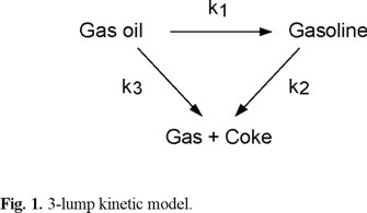
Various complex schemes have been proposed for catalytic cracking reactions [14-17]. However, the 3-lump scheme [1,18], which contains the minimum number of rate constants, is a widely used model. In the present work this model was also used together with different deactivation models. The simple scheme involves parallel cracking of gas oil to gasoline and gas plus coke, with consecutive cracking of the gasoline to gas plus coke (Figure 1).
For gas oil cracking the rate is assumed to be second order

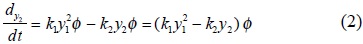
For gasoline cracking the rate is assumed to be first order
The gas + coke yield s determined by the mass balance

3. Deactivation Models
The TOS theory is based on the hypothesis that the concentration of active sites is simply a time-dependent power function of the remaining concentration of active sites and that all of them have the same strength (homogeneous surface) [19,20].

Equation (4) is integrated with the limits tc = 0, φ = 1, for m ≠ 1, to give :
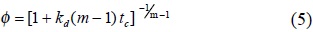
Using equations (4) and (5), the following reported models can be obtained.
Model 1. The integration of equation (4) in the case where the deactivation order (m) is taken equal to 1, gives the exponential law [1,18].

Model 2. Considering the deactivation order equal to 2, a second-order model can be obtained from equation (5) [9].

Model 3. If a higher order is considered (m > 2) and for times-on-stream long enough, the term kd (m − 1)tc, becomes larger than 1. Consequently, equation (5) is equivalent to the power law [18].

where the constants A and N are :

The most used typical form of the power law is φ = tc−N, however, the kinetic parameters evaluated with this function include the deactivation constant in the overall kinetic constant k0A, a combined cracking and decay constant [21].
Model 4. Making G = kd (m − 1) and N = 1 / (m − 1), equation (5) becomes the hyperbolic function [11,19].

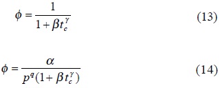
Model 5. In the empirical deactivation model proposed by Oliveira and Biscaira [22] for gasoline cracking (equation (13)), which is basically the model suggested by Jacob et al. [23] without including the gas oil partial pressure effect (equation (14)), if the constant γ is equal to 1, β becomes in kd, similar to Model 2.
4. Experimental
The microactivity test reactor (MAT) is an important tool to measure the activity of FCC catalysts and can also be used for kinetic analysis of the cracking reactions [24]. The MAT technique is a normalized ASTM procedure for a standard feed-stock (ASTM D3907-92). Its main features are: 4 g fixed-bed of catalyst, reaction temperature of 482°C, catalyst-to-oil ratio of 3, WHSV of 16 h−1 and contact time of 75 s. Modified MAT test have been developed in order to cover a wider range of experimental conditions, temperature 482-560°C, catalyst contact time 5-300 s, WHSV of 6-100 [13,25], in the search for testing conditions representative of commercial operation recommended experiments at cat-to-oil of 3, temperature of 516°C, 37.5 s contact time and 32 h−1 of WHSV.
In this study a set of experimental data obtained in a fixed-bed MAT reactor was used to evaluate the kinetic parameters for catalyst deactivation. Experimental runs were performed at a reaction temperature of 500°C and constant cat-to-oil ratio of 5 using an industrial vacuum gas oil over a commercial equilibrium catalyst, both recovered from an industrial FCC plant. Feedstock and catalyst properties are presented in Tables 1 and 2 respectively.


In each experiment, a new portion of equilibrium catalyst was used. The catalyst-to-oil ratio was kept at a constant value by keeping the amount of gas oil injected (0.8 ± 0.005 g) in order to obtain different space velocities. Gas-chromatographic techniques were used for analysis of both the liquid and the gaseous products. The fraction of gasoline was defined by the cut point at 220° C. The product yields were calculated as weight percent of the reactant. A mass balance was performed for each run in the range 100 ± 5% and the conversion in weight percent was evaluated as the sum of C5 + gasoline, C1-C4 gases, hydrogen and coke.
5. Results and Discussion
The data used in the regression analysis were the unconverted gas oil, gasoline and gas plus coke yields in the range of WHSV of 6.1-48.3 h−1. The values of the kinetic and deactivation parameters were determined using a Marquardt non-linear regression technique and are shown in Table 3.

Figures 2 and 3 show the calculated and experimental yields using each deactivation model for gasoline and gas plus coke, respectively.
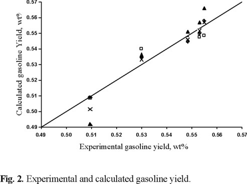

It can be observed from these figures that Models 4 and 5 represent the product yields equally well (r > 0.982 for gasoline and r > 0.995 for gases + coke yields). This is also shown in Table 1 where the corresponding kinetic parameters and the gasoline selectivity given by the k1 / k0 ratio are about the same. The second-order model (Model 2) does not yield a good prediction of experimental results in the range of times-on-stream studied in this work (r ≈ 0.96 for gasoline and gases + coke yields).
The two most popular functions of deactivation catalyst, the exponential law and the power law given by Models 1 and 3 respectively, can reasonably represent the experimental data (r ≈ 0.975 for gasoline and gases + coke yields). However, Models 4 and 5 are slightly superior to Models 1 and 3. It seems that Models 1 and 3 should be used for short times-on-stream as was predicted by Kraemer [21] in two different experimental units for the time range less than 20 s, and Models 4 and 5 for high times-on-stream (> 20 s).
Table 4 shows a comparison of the global gas oil cracking kinetic constant and the deactivation parameters obtained in the present work with those reported in the literature for Models 1, 3 and 4. There is no information available in the literature for the catalyst deactivation in gas oil cracking reactions using Model 5, only for the cracking of gasoline [22].
It can be seen that there are wide differences in the absolute values of kinetic and deactivation constants reported by various authors and the results obtained in this work compare well with some of them.
Figure 4 shows a comparison of calculated and experimental conversion using the five deactivation models. It is evident that Models 4 and 5 are acceptable and they can predict practically the same conversion (r > 0.996) and Model 2 is highly inaccurate for conversion prediction (r ≈ 0.98).

Models 1 and 3 can predict equally well the conversion at short TOS (small conversions) and they become less accurate at high conversions (r ≈ 0.986), specially Model 1.
6. Conclusions
It was found that deactivation of equilibrium catalyst by coke deposition during catalytic cracking of vacuum gas oil can be reasonably and equally well represented using the hyperbolic function (Model 4) and an empirical model (Model 5), in fact, Model 5 has not been used before for this purpose.
The exponential and power laws (Models 1 and 3 respectively) were slightly inferior to Models 4 and 5, however they can represent the catalyst deactivation sufficiently well. The second-order model (Model 2) was highly inaccurate in the range of times-on-stream studied in the present work.
Models 1 and 3 have been widely used by various authors due to the fact that both require only one parameter to be estimated, kd in Model 1 and N in Model 3. However, in order to obtain more accurate yield predictions when studies are performed at high times-on-stream, models which introduce two deactivation parameters, such as Models 4 and 5, should be included in kinetic estimations.
Acknowledgement
The authors wish to thank Instituto Mexicano del Petróleo for their financial support.
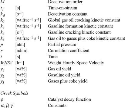
Nomenclature
References
1. Weekman, V.M. Ind. Eng. Chem. Prod. Res. Dev. 1968, 7, 90-95. [ Links ]
2. Krishna, A.S.; Parkin, E.S. Chem. Eng. Prog. 1985, 31, 57-62. [ Links ]
3. Moharir, A.S.; Saraf, S.K. Chem Age of India 1984, 37, 433-440. [ Links ]
4. Nace, D.M. Ind. Eng. Chem. Prod. Res. Dev. 1970, 9, 203-209. [ Links ]
5. Nace, D.M.; Voltz, S.E.; Weekman, V.W. Ind. Eng. Chem. Prod. Res. Dev. 1971, 10, 530-537. [ Links ]
6. Gross, B.; Nace, D.M.; Voltz, S.E. Ind. Eng. Chem. Prod. Res. Dev. 1974, 13, 199-203. [ Links ]
7. Paraskos, J.A.; Shah, Y.T.; McKinney, J.D.; Carr, N.L. Ind. Eng. Chem. Prod. Res. Dev. 1976, 15, 165-169. [ Links ]
8. Shah, Y.T.; Huling, G.P.; Paraskos, J.A.; McKinney, J.D. Ind. Eng. Chem. Prod. Res. Dev. 1997, 16, 89-94. [ Links ]
9. Corella, J.; Bilbao, R.; Molina, J.A.; Artigas, A. Ind. Eng. Chem. Prod. Res. Dev. 1985, 24, 625-636. [ Links ]
10. Grzesik, M.; Skrzypek, J.; Wojciechowsky, B.W. Chem. Eng. Sci. 1990, 45, 267-273. [ Links ]
11. Das, A.K.; Wojciechowsky, B.W. Chem. Eng. Sci. 1992, 1041-1049. [ Links ]
12. Farag, H.; Ng, S.; de Lasa, H. Ind. Eng. Chem. Res. 1993, 32, 1071-1080. [ Links ]
13. Sedran, U.A. Catal. Rev. Sci. Eng. 1994, 36, 425-431. [ Links ]
14. Yen, L.C.; Wrench, R.E.; Ong, A.S. Oil Gas J. 1988, 86, 67-70. [ Links ]
15. Lee, L.S.; Chen, Y.W.; Huang, T.N.; Pan, W.Y. Can. J. Chem. Eng. 1989, 67, 615-619. [ Links ]
16. Corella, J.; Frances, E. Fluid Catalytic Cracking II, ACS Symposium Series 1991, 452, 165-182. [ Links ]
17. Maya, Y.R.; Lopez, I.F. Avances en Ing. Quim. 1993, 14, 39-43. [ Links ]
18. Weekman, V.M.; Nace, D.M. AIChE J. 1970, 16, 397-404. [ Links ]
19. Wojciechowsky, B.M. Can. J. Chem. Eng. 1968, 46, 48-52. [ Links ]
20. Szepe, S.; Levenspiel, O. J. Chem. Eng. Sci. 1968, 60, 127-135. [ Links ]
21. Kraemer, D.; Larocca, M.; de Lasa, H.I. Can. J. Chem. Eng. 1991, 69, 355-360. [ Links ]
22. Oliveira, L.L.; Biscaia, E.C. Ind. Eng. Chem. Res. 1989, 28, 264-271. [ Links ]
23. Jacob, S.M.; Gross, B.; Voltz, S.E.; Weekman, V.W. AIChE J. 1976, 22 (4) 701-713. [ Links ]
24. Wallenstein, D.; Alkemade, U. Appl. Cat. A:General. 1996, 137, 37-54. [ Links ]
25. Campagna, R.J.; Wick, J.P.; Brady. M.F.; Fort, D.L. Oil Gas J. 1986, 85. [ Links ]
26. Corella, J.; Fernandez, A.; Vidal, J.M. Ind. Eng. Chem. Prod. Res. Dev. 1986, 25, 554-562. [ Links ]
27. Larocca, M.; Ng, S.; de Lasa, H. Ind. Eng. Chem. Res. 1990, 29, 171-180. [ Links ]
28. Larocca, M.; Farag, H.; Ng, S.; de Lasa, H. Ind. Eng. Chem. Res. 1990, 29, 2181-2191. [ Links ]

