


 text new page (beta)
 English (pdf)
 Article in xml format
 Article references
 Send this article by e-mail
 Cited by SciELO
  Similars in
SciELO
Similars in
SciELO 
 Permalink
INTRODUCTION
Radiation protection (RP) focuses on the prevention of stochastic and deterministic damage caused by ionizing radiation to workers, the public, and the environment, without interfering with the exposure processes associated with a benefit, ranging from electric power generation to applications in medicine, industry, and agriculture [1] [2] [3].
RP is the responsibility of each country; however, there are international organizations such as the International Atomic Energy Agency (IAEA) and the International Commission on Radiological Protection (ICRP), which issue recommendations on radioprotection to reduce risks and prevent accidents, respond to emergencies associated with radioactive sources and seek to mitigate harmful effects associated with radiological exposure practices; environmental, occupational, or public [3] [4].
It is important to mention that the RP is based on the principles of:
The first two are aimed at the use of the radioactive source, and the third one, for exposed personnel and the public [5], regulating the dose limits in force. In Mexico, the Comisión Nacional de Seguridad Nuclear y Salvaguardias (CNSNS -National Commission for Nuclear Safety and Safeguards-) is the regulatory body for the use of radioactive sources, and the effective dose equivalent were published in the Reglamento General de Seguridad Radiológica (General Regulation of Radiological Safety). These values and the recommended values by the ICRP are measured in millisievert (mSv) and shown in Table 1.
Table 1 Summary of effective exposure limits in planned situations [8] [9].
| Dose limit | Occupationally exposed personnel | Public |
|---|---|---|
| Reglamento General de Seguridad Radiológica | 50 mSv/year for stochastic effects | 5 mSv/year for stochastic effects |
| 500 mSv/year for deterministic effects | 50 mSv/year for deterministic effects | |
| ICRP | 100 mSv/5 years conditional on not exceeding 50 mSv per year | 1 mSv/year |
| Crystalline | 150 mSv | 5 mSv |
| Skin | 500 mSv | 50 mSv |
| Hands and feet | 500 mSv | - |
Also, there are RP factors or practical RP methods [6], which are:
Time: The less time an individual is exposed to a radiation source, the lowest dose absorbed [7].
Distance: Every individual should be as far away as possible from the radiation source, according to the inverse square law of distance, which indicates that it is inversely proportional to the square of the distance from the source [4] [7].
Shielding: Barrier between the source and the individual that reduces the intensity of ionizing radiation [7].
These factors should be considered to optimize the RP design [6]. Regarding shielding, it depends on activity, type of radiation and energy emitted by the source, which is directly related to the type of particles released by the radionuclide (emissions α, β+, β-, γ, etc.) [7], as well as the density and thickness of the material. Nowadays, the most used materials are concrete, lead, and steel [7] [10], whose description and density are shown in Table 2.
Table 2 Examples of radiológical shielding materials [11].
| Material | Comments |
|---|---|
| Concrete | Its density varies with mineral content. |
| Steel /Lead | It is normally used as supplementary shielding. |
Regarding medical use, radioactive sources are used in diagnosis, treatment [1], and theragnostic [12]. Particularly in treatments, there are teletherapy and brachytherapy.
Brachytherapy is a treatment in which radioactive sources are placed at a short distance from the tumor. It is classified according to dose rate or how quickly the dose is delivered to the patient: low, medium, and high [13]. In the case of High Dose Rate Brachytherapy (HDR-B), the most radioactive isotopes used are Cobalt-60 (60Co) and Iridium-192 (192Ir) [11]. Particularly, 192Ir has a half-life of 73,829 days and decays 95.35% by particle emission β and 4.65% by Electronic Capture (EC) to excited states of Platinum-192 (192Pt) and Osmium-192 (192Os) respectively. Afterwards, they decay by emission γ until they reach stability (Figure 1)[14] [15]. Exposure to high levels of γ-rays cause harmful effects (for example cancer), which is why a barrier is used to attenuate them (mainly by photoelectric effect and Compton effect) [16].
Shielding depends on the design of the HDR-B treatment room. Therefore, the IAEA suggests a room design with a doorless maze for 60Co radioactive source, includes a control area, preparation/procedure room, recovery area, sluice room, and image processing area (Figure 2)[17]. The dimensions for the width of the maze should be 1.8 meters (m), the internal ones 4 m long by 4 m wide (Figure 2, and a height of 3 to 3.6 m. The above, assuming the use of fluoroscopy equipment for applicator placement [11], although Computed Tomography (CT) and Magnetic Resonance Imaging (MRI) simulation is also used [17].
Figure 2 Brachytherapy treatment room for 60Co source suggested by IAEA: dimensions and adjoining areas[17].
Calculation of primary barriers
IAEA Safety Report Series No. 47 (SRS-47) describes a method for calculating shielding thicknesses in walls, floor, and roof and considerations as primary barriers (shielding where useful radiation beam hits directly). This method starts from the calculation of the attenuation required by the barrier (B) given a dosimetry shielding point that is at a certain distance from the source (d) [4] [11] [18]. Thus, B is determined from Equation (1):
Where P is the design limit measured in µGy week-1, W is the workload in micro grays per square meter week-1 (µGy m2 week-1), U is the use factor, and T is the occupancy factor ofadjacent areas [11].
Concerning P, it must ensure compliance with the permissible exposure dose limits for adjacent areas. The classification of the adjacent areas is:
Controlled: areas with specific protective measures to control potential exposures under normal working conditions. The limit is P equal to 120 microsievertperweek(µGy week-1) [11] [16].
Uncontrolled (public): areas that are not designated as controlled but are under review. The design limit is 6 µGy week-1 [11] [16].
About W, it refers to thedose administered per treatment each time (usually in one week) [4] [11]. It is calculated by the Equation (2)[11]:
Where RAKR is the Reference Air Kerma Rate for a source of unit activityat one-meter distance modified by attenuation and scattering in the air [16]; A is the total source activity measured in becquerels (Bq); t is the average treatment duration in hours,and n is the number of treatments per week [11].
According to the American Association of Medical Physicists Publication No. 21 (AAPM-21), W is determined by the Equation (3)[19]:
Where Sk is the air kerma strength of the source in units of U o (μGy m2)/h and it is equivalent to the product of RAKR times A [19].
For the T factor, it indicates the average fraction of time that a person is mostly exposed to adjacent area where the source is in use. Table 3 shows the value for each area according to NCRP Report No.49(NCRP-49) [4] [10] [11].
Table 3 Occupancy factor t recommended bythe NCRP-49 [10][11].
| Type of area | T |
|---|---|
| Offices, laboratories, shops, children's play areas, nurse's stations, staff rooms. Control room, patient rooms. | 1 |
| Corridors. | 1/ 4 |
| Waiting rooms, toilets, stairways, unattended elevators, vehicular traffic. | 1/16 |
It is important to mention that for HDR-B, the sources are isotropic, i.e., they are not collimated, and their emissions are in all directions. In this sense, the U factor willalways beequal to 1[4] [11].
It is also recommended the use of the Tenth Value Layer (TVL) and Half Value Layer (HVL), which reduce the radiation intensity by a factor of one tenth and one half of the initial intensity, respectively, whose thickness is specific foreach material and radionuclide [11]. The number of TVL that produces a transmission factor B is calculated from the Equation (4)[11]:
So, the barrier thickness (Et) is obtained by multiplying the TVL times the TVL value of the material (TVLm) [11], as shown in the Equation (5):
Calculation of secondary barriers
In addition, secondary radiation must be considered, especially that transmitted into the maze. For which, the factor B for the secondary barriers (barriers not in direct contact with the radiation beam from the source), is calculated from Equation (6)[11]:
Where dsca isthedistancefromthe radiation source to the patient in meters (m); dsec is the distance from the patient to thepoint of interestin m; a is the beam energy scattering fraction and scattering angle in dsca; F is the incident field areaoverthe patient insquarecentimeters (cm2).
MATERIALS ANDMETHODS
The method consists of three stages: the first is to identify the room design data, source characteristics, design limits and shielding material. The second stage is to determine the number of dosimetric point per wall and roof, calculating the shielding using the IAEA SRS-47 method (described previously) for each point, and obtain the area and volume of each barrier. The last stage involves calculating and analyzing the shielding reduction percentages (Figure 3.

First, the data of the HDR-B room are identified, considering the design, dimensions, and adjacent areas shown in Figure 4, having as primary barriers wall A, B, D, and E, and a distinction of primary and secondary barriers, on wall C and the roof.

For this case, we consider the use of an 192Ir source with a nominal activity of 370 Gigabecquerel (GBq), RAKR of 0.111 µGy · MBq1 -m2*h-1 [11], total activity (A) of 555 GBq [20], a workload (n) of 30 treatments per week, with an average treatment duration (t) of 10 minutes (0.167 hours) to deliver an absorbed dose of 7.5 Gy, to the prescription point per treatment and con crete as shielding material, whose TVL value for this source is 0.152 m [11].
Also, the value for the factor T and the design limit P is established according to the adjacent area and NCRP 49 (values shown in Table 3[10]. The assignment of these values is shown in Table 4.
Table 4 Summary of values used according to the NCRP.
| Barrier | Adjacent area | T | Type of area | P [µSv week-1] |
|---|---|---|---|---|
| A | Garden | 1/16 | Uncontrolled | 6 |
| B | Garden | 1/16 | Uncontrolled | 6 |
| C | Recovery room | 1/16 | Uncontrolled | 6 |
| D | Control room | 1 | Controlled | 120 |
| E | Maze | 1/16 | Uncontrolled | 6 |
| Roof | None | 1/16 | Uncontrolled | 6 |
For the second stage, the barriers A, B, D and E are divided into 4 (5 points) and 10 (11 points) equal parts (see example in Figure 5, for 5 points), where for each division point (dosimetric points) and distances closer to the source (dA, dB, dD and dE) the following calculations are performed:
Figure 5 Location of 5 dosimetric points on barrier A, as well as the closest distances from the source to the walls of the HDR-B treatment room.
First, the distances f the points to the source (distance between two points) are calculated, using the Equation (7)[21].
For this purpose, the positions (x, y, z) of the dosim etric points on the cartesian plane, represented by the HDR-B room, are considered. Which has origin (0, 0) at the lower left and the source position at (x0 = 3, y0= 2.5, z0= 1.1) (Figure 4.
Then, the W factor is calculated by substituting the values of RAKR, A, t , aod n, in the Equation (2), which results:
The shielding thickness i s then calculated for each of the points of each barrier, substituting the values of P, W, U, T, and d the in Equation (1), obtaining:
The obtained value 05 B is thensubstituted into the Equation (4) to calculate -the number of TVL:
The result and the TVL valué of the concrete for 192Ir are substituted in the Equation (5), resulting:
Once all the points of barriers A, B, D, and E have been obtained, the area of each barrier is calculated by obtaining the areas of the rectangular trapezoids (atr) formed by the thicknesses of each dosimetric, as shown in Figure 6. This calculation is performed with the Equation (8)[22]:
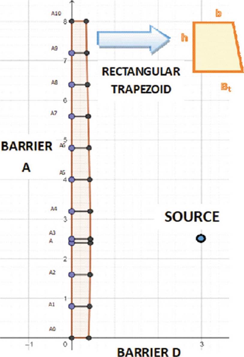
Figure 6 Rectangular trapezoid formed by the point A9 and A10 of the 11-point fractionation of the barrier A.
Where Bt is the major base (lower thickness), and b is the minor base (upper thickness), and h is the height (dosimetric point spacing).
The sum of the areas of the rectangular trapezoids provides the area of each barrier. Subsequently, it is multiplied by the height of the room, which is 3.5 meters, to obtain the volume.
In the case of the wall C, it is divided into two sections (Figure 4). For the first section, the distance dc1 is considered and the shielding thickness is calculated using the calculations described for barriers A, B, D, and E. For the second section, the distance from the source to the middle of the maze on wall B (dsec) having coordinates (6.8, 8) (Figure 4 is calculated using the Equation (7), resulting:
For this case, we considered the dsca value of 1.5 m and a maximum F of 400 cm2 and a reflection angle of 45° for 60Co (α) of 0.0037 [11]; these values and the values of T, P, and W (calculated previously) are substituted in Equation (6) to obtain the factor B, resulting:
Then, the value of B is substituted in the Equation (4) and subsequently, Equation (5)are used to obtain the final thickness. The area is calculated by multiplying the width of the barrier (2.4 m for the first section and 5.6 m times the second section) and the sum of these are multiplied times the height (3.5 m) to obtain the volume.
For the roof shield calculation, it is divided into two sections (Figure 7).

In the case of the first section, the fractionation into 5 and 11 divisions is performed on the position of the source on the x-axis (indicated with a black line in Figure 7. The calculations of the distances are carried out in the dimensions (x, y, z) with the Equation (7), the shortest distance to the source (3, 2.5, 3.5), and the position (3, 5.6, 3.5) are also considered.
Then, for each of the distances obtained, the thickness is calculated using the Equations (1), (4), and (5).
To obtain the area, Equation (8) is used in the same way with barriers A, B, D, and E. These areas are multiplied by the width of each section and the result is multiplied by the length of the room (5.6 m or 8 m) to obtain the volume.
The second section is analyzed as a secondary barrier, so the distance from the point d (6.8, 8, 3.5) (Figure 7 is calculated using the Equation (7). Subsequently, B is calculated with the Equation (6), consid ering the same values of d, F, and α. The shielding thickness is calculated using the Equations (4) and (5).
The area is obtained by multiplying the thickness times the length of the section (5.6 m). The result is multiplied by the width of the section (2.4 m) to obtain the volume.
As for the reference volume values, they are calculated by multiplying the thickness of the points dA, dB, dD, dC, dE and dT, times the length of each barrier (area), the result is multiplied by the height.
For the third stage, the percentage of reduction is calculated by comparing the volume calculated at one point in each of the barriers against this obtained for 5 and 11 points.
Also, the geometric mean (G) is calculated at the reduction percentages per barrier, which is defined as the root- nth (N) of the product of all the elements (n), represented by the Equation (9)[23] [24]:
As for the total percentage of the reduced shielding of the HDR-B room, it is calculated by adding the volumes of all barriers at one, 5, and 11 points. Subsequently, a comparison is made of the required shielding volume at one point vs. 5 points and one point vs. 11 points.
RESULTS AND DISCUSSION
From the previous study, Tables 5 and 6 were obtained as a result of the fractionation of barriers A, B, D, and E for 5 and 11 points, where x and y indicate the positions of each dosimetric point, d is the calculated distance from the point to the source measured in meters, Et is the required shielding thickness in meters, a is the area obtained from each rectangular trapezoid, ac is the sum of the areas of the rectangular trapezoids comprising the barrier.
Table 5 Shielding for barriers A, B, D and E, for 5 points.
| Barrier | N° | x | y | d [m] |
Et [m] |
atr [m2] |
ac [m2] |
Volume [m3] |
|---|---|---|---|---|---|---|---|---|
| A | 0 | 0.000 | 0.000 | 3.905 | 0.350 | 2.831 | 9.909 | |
| 1 | 0.000 | 2.000 | 3.041 | 0.383 | 0.733 | |||
| dA | 0.000 | 2.500 | 3.000 | 0.383 | 0.192 | |||
| 2 | 0.000 | 4.000 | 3.354 | 0.383 | 0.575 | |||
| 3 | 0.000 | 6.000 | 4.610 | 0.328 | 0.711 | |||
| 4 | 0.000 | 8.000 | 6.265 | 0.292 | 0.620 | |||
| B | 0 | 0.000 | 8.000 | 6.265 | 0.292 | 2.369 | 8.292 | |
| 1 | 2.000 | 8.000 | 5.590 | 0.304 | 0.596 | |||
| dB | 3.000 | 8.000 | 5.500 | 0.311 | 0.308 | |||
| 2 | 4.000 | 8.000 | 5.590 | 0.304 | 0.308 | |||
| 3 | 6.000 | 8.000 | 6.265 | 0.292 | 0.596 | |||
| 4 | 8.000 | 8.000 | 7.433 | 0.269 | 0.561 | |||
| D | 0 | 0.000 | 0.000 | 3.905 | 0.338 | 2.131 | 7.459 | |
| 1 | 1.400 | 0.000 | 2.968 | 0.383 | 0.505 | |||
| 2 | 2.800 | 0.000 | 2.508 | 0.410 | 0.555 | |||
| dD | 3.000 | 0.000 | 2.500 | 0.410 | 0.082 | |||
| 3 | 4.200 | 0.000 | 2.773 | 0.383 | 0.476 | |||
| 4 | 5.600 | 0.000 | 3.607 | 0.350 | 0.513 | |||
| E | 0 | 5.600 | 0.000 | 3.607 | 0.364 | 2.184 | 7.644 | |
| 1 | 5.600 | 1.400 | 2.823 | 0.410 | 0.542 | |||
| dE | 5.600 | 2.500 | 2.600 | 0.410 | 0.451 | |||
| 2 | 5.600 | 2.800 | 2.617 | 0.410 | 0.123 | |||
| 3 | 5.600 | 4.200 | 3.106 | 0.383 | 0.555 | |||
| 4 | 5.600 | 5.600 | 4.046 | 0.350 | 0.513 |
Table 6 Shielding for barriers A, B, D and E, for 11 points.
| Barrier | N° | x | y | d [m] |
Et [m] |
atr [m2] |
ac [m2] |
Volumen [m3] |
|---|---|---|---|---|---|---|---|---|
| A | 0 | 0.000 | 0.000 | 3.905 | 0.350 | 2.833 | 9.916 | |
| 1 | 0.000 | 0.800 | 3.448 | 0.364 | 0.286 | |||
| 2 | 0.000 | 1.600 | 3.132 | 0.383 | 0.299 | |||
| 3 | 0.000 | 2.400 | 3.002 | 0.383 | 0.306 | |||
| dA | 0.000 | 2.500 | 3.000 | 0.383 | 0.038 | |||
| 4 | 0.000 | 3.200 | 3.081 | 0.383 | 0.268 | |||
| 5 | 0.000 | 4.000 | 3.354 | 0.383 | 0.306 | |||
| 6 | 0.000 | 4.800 | 3.780 | 0.364 | 0.299 | |||
| 7 | 0.000 | 5.600 | 4.314 | 0.338 | 0.281 | |||
| 8 | 0.000 | 6.400 | 4.920 | 0.319 | 0.263 | |||
| 9 | 0.000 | 7.200 | 5.576 | 0.304 | 0.249 | |||
| 10 | 0.000 | 8.000 | 6.265 | 0.292 | 0.238 | |||
| B | 0 | 0.000 | 8.000 | 6.265 | 0.292 | 2.370 | 8.295 | |
| 1 | 0.800 | 8.000 | 5.924 | 0.298 | 0.236 | |||
| 2 | 1.600 | 8.000 | 5.675 | 0.304 | 0.241 | |||
| 3 | 2.400 | 8.000 | 5.533 | 0.304 | 0.243 | |||
| dB | 3.000 | 8.000 | 5.500 | 0.311 | 0.185 | |||
| 4 | 3.200 | 8.000 | 5.504 | 0.311 | 0.062 | |||
| 5 | 4.000 | 8.000 | 5.590 | 0.304 | 0.246 | |||
| 6 | 4.800 | 8.000 | 5.787 | 0.304 | 0.243 | |||
| 7 | 5.600 | 8.000 | 6.084 | 0.292 | 0.238 | |||
| 8 | 6.400 | 8.000 | 6.466 | 0.287 | 0.232 | |||
| 9 | 7.200 | 8.000 | 6.920 | 0.277 | 0.226 | |||
| 10 | 8.000 | 8.000 | 7.433 | 0.269 | 0.218 | |||
| D | 0 | 0.000 | 0.000 | 3.905 | 0.338 | 2.113 | 7.396 | |
| 1 | 0.600 | 0.000 | 3.493 | 0.350 | 0.193 | |||
| 2 | 1.100 | 0.000 | 3.128 | 0.364 | 0.200 | |||
| 3 | 1.700 | 0.000 | 2.827 | 0.383 | 0.209 | |||
| 4 | 2.200 | 0.000 | 2.613 | 0.383 | 0.214 | |||
| 5 | 2.800 | 0.000 | 2.508 | 0.410 | 0.222 | |||
| dD | 3.000 | 0.000 | 2.500 | 0.410 | 0.082 | |||
| 6 | 3.400 | 0.000 | 2.526 | 0.410 | 0.148 | |||
| 7 | 3.900 | 0.000 | 2.664 | 0.383 | 0.222 | |||
| 8 | 4.500 | 0.000 | 2.905 | 0.383 | 0.214 | |||
| 9 | 5.000 | 0.000 | 3.227 | 0.364 | 0.209 | |||
| 10 | 5.600 | 0.000 | 3.607 | 0.350 | 0.200 | |||
| E | 0 | 5.600 | 0.000 | 3.607 | 0.364 | 2.180 | 7.630 | |
| 1 | 5.600 | 0.600 | 3.244 | 0.383 | 0.209 | |||
| 2 | 5.600 | 1.100 | 2.944 | 0.383 | 0.214 | |||
| 3 | 5.600 | 1.700 | 2.726 | 0.410 | 0.222 | |||
| 4 | 5.600 | 2.200 | 2.613 | 0.410 | 0.230 | |||
| dE | 5.600 | 2.500 | 2.600 | 0.410 | 0.107 | |||
| 5 | 5.600 | 2.800 | 2.617 | 0.410 | 0.123 | |||
| 6 | 5.600 | 3.400 | 2.739 | 0.410 | 0.230 | |||
| 7 | 5.600 | 3.900 | 2.962 | 0.383 | 0.222 | |||
| 8 | 5.600 | 4.500 | 3.268 | 0.383 | 0.214 | |||
| 9 | 5.600 | 5.000 | 3.635 | 0.364 | 0.209 | |||
| 10 | 5.600 | 5.600 | 4.046 | 0.350 | 0.200 |
According to Figure 8, we can observe that in barrier A, there is a decreasing trend in the thickness of the shielding thickness from 10.724 m3 of concrete calculated for one point to 9.909 m3 for 5 points and 9.916 m3 for 11 points. This behavior represents a percentage decrease of 7.600% and 7.535% (Table 7), respectively.

Table 7 Percentage of volume reduced by barrier.
| Number of points |
A [% ] | B [% ] | C [% ] | D [% ] | E [% ] | Roof [ %] |
|---|---|---|---|---|---|---|
| 5 | 7.600 | 4.777 | 65.472 | 7.180 | 4.878 | 22.100 |
| 11 | 7.535 | 4.743 | 65.472 | 7.964 | 5.052 | 24.901 |
Also, in barrier there is B a decrease from 8.708 m3 at one point to 8.292 m3 at 5 points and 8.295 m3 at 11 points (Figure 8). The percentage decrease is 4.777% and 4.743%, respectively (Table 7).
A similar case is barrier D, the volume decreased from 8.036 m3 for one point to 7.459 m3 for 5 points and 7.396 m3 for 11 points (Figure 8), representing a decrease of 7.180% and 7.964% (Table 7), respectively.
For barrier E, the volume calculated for one point is 8.036 m3, while for 5 points it is 7.644 m3 and for 11 points it is 7.630 m3 (Figure 8, representing a percentage decrease of 4.878% and 5.052% (Table 7) respectively.
In the case of barrier C, it represents the best reduction in shielding, since a single point requires 8.932 m3 of concrete, while with the proposed method the volume required is 3.084 m3 (Table 8). This difference represents a 65.472% of reduction in the shielding volume (Table 7).
Table 8 Shielding for barrier C.
| Number of points |
Section | x | y | d [m] | Et [m] | a [m2] | ac [m2] | Volume
[m3] |
|---|---|---|---|---|---|---|---|---|
| 1 | dc | 8.00 | 2.50 | 5.000 | 0.319 | - | - | 8.932 |
| First section | 1 | 8.00 | 8.00 | 7.433 | 0.269 | 0.646 | 0.881 | 3.084 |
| Second section | 2 | 6.80 | 8.00 | 6.685 | 0.042 | 0.235 |
For roof shielding, the volume requiredforone point is 26.240 m3 (Figure 8), meanwhile for5 and11 points, they were 20.441 m3 and 19.706 m3 respectively (Table 9), representing a reduction percentage of 22.100% and 24.901% respectively.
Table 9 Armoring for the roof.
| Number of points |
N° | x | y | z | d [m] | Et [m] | atr [m2] | V[tr] [m3] | Volume [m3] |
|---|---|---|---|---|---|---|---|---|---|
| 5 | 0 | 3.000 | 0.000 | 3.500 | 3.466 | 0.364 | 20.441 | ||
| 1 | 3.000 | 2.000 | 3.500 | 2.452 | 0.410 | 0.774 | 4.334 | ||
| 2 | 3.000 | 2.400 | 3.500 | 2.402 | 0.410 | 0.164 | 0.918 | ||
| dt | 3.000 | 2.500 | 3.500 | 2.400 | 0.410 | 0.041 | 0.230 | ||
| 2 | 3.000 | 4.000 | 3.500 | 2.830 | 0.410 | 0.615 | 3.444 | ||
| 3 | 3.000 | 5.600 | 3.500 | 3.920 | 0.350 | 0.608 | 4.864 | ||
| 4 | 3.000 | 6.000 | 3.500 | 4.244 | 0.338 | 0.138 | 1.104 | ||
| 5 | 3.000 | 8.000 | 3.500 | 6.001 | 0.298 | 0.636 | 5.088 | ||
| dl | 6.800 | 8.000 | 3.500 | 7.103 | 0.034 | 0.082 | 0.459 | ||
| 11 | 0 | 3.000 | 0.000 | 3.500 | 3.466 | 0.364 | 19.706 | ||
| 1 | 3.000 | 0.800 | 3.500 | 2.941 | 0.383 | 0.299 | 1.674 | ||
| 2 | 3.000 | 1.600 | 3.500 | 2.563 | 0.410 | 0.317 | 1.775 | ||
| 3 | 3.000 | 2.400 | 3.500 | 2.402 | 0.410 | 0.328 | 1.837 | ||
| Dt | 3.000 | 2.500 | 3.500 | 2.400 | 0.410 | 0.041 | 0.230 | ||
| 4 | 3.000 | 3.200 | 3.500 | 2.500 | 0.410 | 0.287 | 1.607 | ||
| 5 | 3.000 | 4.000 | 3.500 | 2.830 | 0.410 | 0.328 | 1.837 | ||
| 6 | 3.000 | 4.800 | 3.500 | 3.324 | 0.383 | 0.317 | 1.775 | ||
| 7 | 3.000 | 5.600 | 3.500 | 3.920 | 0.350 | 0.293 | 2.344 | ||
| 8 | 3.000 | 6.400 | 3.500 | 4.579 | 0.328 | 0.271 | 2.168 | ||
| 9 | 3.000 | 7.200 | 3.500 | 5.277 | 0.311 | 0.256 | 2.048 | ||
| 10 | 3.000 | 8.000 | 3.500 | 6.001 | 0.298 | 0.244 | 1.952 | ||
| dl | 6.800 | 8.000 | 3.500 | 7.103 | 0.034 | 0.082 | 0.459 |
The calculation of the geometric mean of the reduction percentages per wall at 5 points yielded a reduction percentage of 11.070%, while for 11 points it was 11.526%.
In addition, the shielding volume required for the HDR-B room at one point is 70.676 m3, while for fractionation at 5 points requires 56.829 m3 and at 11 points 56.027 m3, representing a percentage decrease of 19.592% and 20.727%, respectively (Table 10).
Table 10 Percentage of total volume reduced by 5 and 11 points.
| Number of points |
Total volume
[m3] |
Reduced volume [% ] |
|---|---|---|
| 1 | 70.676 | - |
| 5 | 56.829 | 19.592 |
| 11 | 56.027 | 20.727 |
It is important to mention that, currently the design methods for shielding a HDR-B room are determined in accordance with the reports of the NCRP (No. 49, 151, 151, and 155) and IAEA SRS-47, which establish the calculation of shielding thickness starting from the closest points to the source [4] [10] [11] [25]. However, knowing that gamma-ray attenuation is related to the interaction with matter, represented by the Equation (10):
Where I(x) is the intensity of gamma-rays as a function of distance x in the material and g is the linear attenuation coefficient which depends on the energy of the gamma rays and the material which they interact with [26] [27], it is possible to compare an analysis based on fractionation of the barriers (proposed in Figure 3, derived from the fact that it is known that increasing the distance between the focal point (source) and the interaction point (dosimetric point) the amount of radiation is decreased by the inverse square law of the distance [7] [18] [26] [28] [29].
In this sense, a reduction in the volume of shielding was obtained in all barriers calculated with the proposed method (Figure 8), the most significant reduction percentage is 65.472% in the C barrier (Table 7). In the other barriers, the reduction was lower because the distances from the points to the source do not present much difference between them. One example is barrier B, divided into 11 points (Table 6), most of the calculated distances (column d[m]) are within the range from 5.500 to 7.433 m.
It is important to point out, according to Table 10, the volume calculated at 5 points (56.829 m3) is higher than at 11 points (56.027 m3); it can be inferred that the smaller the separation distance between the points, the higher the accuracy of the shielding calculation, since more intermediate points are considered. The most significant example is the roof, whose difference between the shielding volume calculated at 5 (is 20.441 m3) and 11 points (19.706 m3) is 0.735 m3 (Table 9).
Also, IAEA document SRS-47 recommends that for HDR-B room the shielding barriers should be primary because when the source is in use, it is isotropic and without collimation [11] [17] [31] [33]. However, it was analyzed that both in the second section of the C barrier (Figure 5) and in the second section of the roof (Figure 7) there is no primary radiation, but the radiation transmitted through by the E barrier and the scattered radiation, product of the reflection on barrier B. Therefore, and considering the cost-benefit, it is possible to consider these sections as secondary barriers, otherwise; it implies calculating an excessively and unnecessary thickness, which implies the requirement of more material, space, and economic resources [30] [34] [35].
It should be noted that there is no specific recommendation or method for the analysis of secondary radiation. Even estimating the absorbed dose at the entrance of the maze is difficult, so in practice, various methods have been adopted, ranging from considering only direct radiation or scattered radiation [4] [11].
In the case of the secondary radiation analysis, the value used for α corresponds to 60Co, because in the IAEA SRS-47 report, it is not available for 192Ir. In addition, 60Co has a gamma-ray energy value (of 1.25 MeV) higher than that of 192Ir (0.375 MeV), thus ensuring that the calculation is effective [11] [26] [36].
It is important to mention that this study does not contemplate the affectation of rear shielding derived from the elimination of part of it to install ducts and boxes embedded in walls, roofs and floors, hardware in lead-lined doors or concrete block joints, since these adaptations are specific to each HDR-B room [30] [37].
Similarly, it does not include the shielding analysis for the floor, because it is assumed that the HDR-B room is on the ground level does not affect any piping or drainage [32]. However, if necessary, it can be performed in the same way as for the roof.
Although the design of the HDR-B room is related to space and available resources, this method is intended as a strategy to reduce construction costs without failing to comply with national and international regulations regarding exposure dose limits for exposed personnel and the public, and also, to optimize resources to be allocated to other expenses such as the cost of equipment, radioactive sources, auxiliary equipment, service and maintenance costs, training and salaries of personnel [26] [31] [34] [37] [38].
In this sense, a cost-benefit analysis of the fractional shielding calculation could be expected to be effective in RP and cheaper in shielding material cost with respect to the IAEA SRS-47 methodology. However, the option of having an RP surveillance program is not ruled out [32] [34] [39].
As for the geometric mean calculated for the percentages reduced in each barrier (Table 7), it was obtained that, for the fractionation in 5 points, it was 11.070%, meanwhile for 11 points it was 11.526%. This indicates that the shielding reduction in the DHR-B room barriers is reduced by at least 11%.
Thus, the proposed method for the calculation of shielding for HDR-B rooms, which starts from the RP and optimizes space and economic resources allocated, a concrete reduction of 19.592% and 20.727% was obtained for the fractionation in 5 and 11 points respectively (Table 10), which makes it more beneficial compared to conventionally method using the IAEA 47.
CONCLUSIONS
According to the results obtained and basing this model on the IAEA SRS-47 methodology, it is concluded that through the fractional calculation of shielding and the distinction of primary and secondary barriers, it is possible to reduce 19.592% and 20.727% of construction material for the fractionation in 5 and 11 points respectively, in a brachytherapy room with maze; optimizing costs without affecting the PR guidelines for exposed workers and public in adjacent areas.
This difference of percentage is related to the fractionation of the barriers, where the higher the fractionation, the higher the accuracy of the shielding calculation. This possible error is mitigated by including an HVL layer; however, an RP monitoring program is not rejected.
Finally, this study opens the way to be used in the design of shielding with other methodologies and in other areas with the use of ionizing radiation sources.

