


 nueva página del texto (beta)
 Inglés (pdf)
 Artículo en XML
 Referencias del artículo
 Enviar artículo por email
 Citado por SciELO
  Similares en
SciELO
Similares en
SciELO 
 Permalink
Introduction
One million cerebrovascular diseases were reported in Mexico in 20081, most of the survivors of these cases continued to have hand mobility problems two years after the stroke2. In 2010 in Mexico, 5 739 270 persons were reported with some kind of disability, this number represented the 5.1% of total population that year1, some of these disabilities were caused by stroke. In 2010 in Japan more than 70,000 patients of cervical spine injury were reported3. In the USA in 2015, about 795 000 people had stroke4. In 2010, 16.9 million people worldwide had a stroke for the first time4. Some of the most common consequences of these disabilities are the limitation in force and mobility of the hand fingers. In general terms, people with levels smaller than 3 in the Manual Muscle Testing Grading System (MMTGS) need external help to develop the Activities of Daily Living (ADL). Level 3 in MMTGS corresponds to a full Range of Motion (ROM) against gravity and slight resistance.
Stroke survivors must follow a rehabilitation program, some of these survivors that completed their rehabilitation program for upper limbs only recovered the motor function in shoulders and wrists, but the mobility in hands and fingers was limited5,6. The fingers rehabilitation basically consists of actively moving the fingers and thus reactivating the muscles associated to them. The fingers can move on a 3D workspace, reached by the flexion-extension and adduction-abduction movements of the joints. In a rehabilitation protocol, usually, the adduction-abduction movement is skipped (except for the thumb), and thus it generates a 2D and more simple workspace, as it is pointed out by Cruz, et al.7
The use of robotic devices is increasing, the motor therapy is showing a great potential, some benefits of the rehabilitation with robots include the ability to develop precise and repeatable therapeutic exercises8, a safe and intensive training9,10, a significant improvement in the behavior of the affected limbs11 and an intensive motor improvement in chronic stroke12.
Nowadays there are several devices to help in hand rehabilitation, mainly for stroke survivors. The options that we find in the literature go from training weak muscles with devices to exoskeletons than help the hand generate a bigger grip force. These devices are designed mostly for the user to spend some therapy time in a specialized place, adequate for the patient training.
Some of the designs of the rehabilitation devices are: Cybergrasp which is an exoskeleton situated on the hand dorsum, used to exert force on each individual finger, this exoskeleton is used on a robotic/virtual environment to train the hand of persons with hemiparesis13; Hand Mentor is a system for hand rehabilitation by active motion of all the fingers, the device provides a controlled resistive force by a pneumatic muscle14; the Hand Wrist Assistive Rehabilitation Device (HWARD) is actuated pneumatically, the device can flex the thumb and simultaneously the four fingers11; the Exoskeleton Hand Robotic Training Device is designed specially to be used by persons after stroke, it is driven by the patient muscle signals15; HANDEXOS is an exoskeleton for rehabilitation of the hand for patients after stroke, the device is composed by some shell structures connected by translational and rotational joints that allow the fingers flexion16. Others devices under development are: the orthosis designed for Patara et al.17 which uses one air cylinder to flex the four fingers, it is composed by a cam and a set of links; the active hand orthosis designed by Rosati et al.18 for the acute and sub-acute phase after stroke employs one elastic actuator to produce the force to flex the four fingers at the same time; the device proposed by Lambercy et al.19 is a exoskeleton thumb that can perform the flexion-extension and abduction-adduction movements using a linear servomotor; the device developed by Morogumi et al.3 is an orthosis to support ADL for patients with cervical spinal cord injury, the device uses a servomotor and a compression spring to open/close the four fingers; the upper limb orthosis designed by Sooraj et al.20 provides bi-directional haptic feedback, this orthosis is designed to improve the locomotion capability and increases the endurance through physical rehabilitation exercises; Tjahyono et al.21 developed a five-fingered hand exoskeleton that is driven by pneumatic muscles; the wearable exoskeleton designed by Zhang et al.22 uses Bowden cables to flex the three joints of two fingers in a bidirectional way; the five-fingered hand exoskeleton proposed by Sandoval-González et al.23 uses DC motors to flex all phalanxes individually; the robotic hand exoskeleton designed by Leonardis et al.24 is conceived to support stroke patients in cylindrical grasping, has two DC motors and two degree of freedom, one for the fingers and one for the thumb. All the above mentioned devices were obtained through a specific design process; however, the designers of those mechanisms do no report if they have been obtained through an optimal process.
The devices where the optimization is considered are briefly presented below: the seven-bar linkage presented on25 is force and kinematically synthesized, the mechanism has a semicircular slider which is used for switch between pinching or grasping tasks; exoskeleton presented on26 is composed by a two four-bar linkage, the mechanism is synthetized to follow a specific fingertip path; the underactuated mechanism described on27, 28 is optimized to flex two phalanxes and enhance the force capabilities of the finger, the optimization process is based on a kinetostatic analysis; a synthesis of a six-bar linkage for a hand rehabilitation robot is detailed on 29, the mechanism is obtained using both geometrical and body-guidance synthesis.
This paper presents an optimal mechanical design of an orthosis for finger rehabilitation; the orthosis is useful to assist the flexion-extension movement of the middle finger. The orthosis weight and volume are adequate to be used by a patient during all day (maximum 1 N for each finger) and thus he can rehabilitate by himself while performing the Activities of Daily Living. The originality on the proposed mechanism is the use of rigid linkages to flex the three phalanxes at the same time, using only one degree of mobility. The mechanism is formed by sixteen joints and twelve bodies, three of them have a semicircular slider.
Material and methods
Design Factors
In this work we used anthropometric data of the percentile 50 of the human hand of Mexico City's population, presented by 30. The design factors taken into account are: the orthosis must be fixed to the dorsal side of the hand; it should not alter the flexion-extension natural movement of the finger; the orthosis should not interfere in object grasping (palmar side must be free); the orthosis must conduct each of the three phalanx through all ROM of flexion-extension using only one degree of freedom; the three joints must move at the same time; the orthosis should follow a path created by the midpoints of the dorsal-side of the middle finger (see Figure 1); the orthosis must have a weight w that allows it to be used by a person during a whole day of activities (for instance, w≤1 N). These design factors were proposed by the authors after several talks with therapists moreover considering the orthosis must be useful to perform ADL.

Figure 1 shows the paths followed by the midpoints (d1, h1 and s1) of the phalanxes: d1 corresponds to the proximal phalanx, h1 to the medial phalanx and s1 to the distal phalanx.
Mechanical Design
The mechanism is formed by rigid links, we considered the configuration proposed by Ho et al.15 and we added four more links to achieve the movement of the distal phalanx. The mechanism configuration and the number of bodies (ground and posed By Suh and Radcliffe32. The mechanism has twelve bodies and sixteen joints; therefore, it has one degree of freedom (DOF). System variables are shown in Figure 3, the angles θ1 to θ11 represent the angular orientation of the respective body and x1 represents the displacement of the linear actuator.
System Analysis
In Figure 2, a0 and b0 points are fixed to the ground (a structure coupled to the dorsal side of the hand). Bodies 1 and 2 correspond to a linear actuator (which is considered like a linear slider), body 1 is the fixed part and body 2 is the moving part; all other bodies are rigid links (from body 3 to body 11). Point a_1 moves inside a slider with a semicircular path, which has a center of rotation coincident with the metacarpophalangeal joint (O3 point); point g1 moves inside a second slider with semicircular path with center of rotation coincident with the proximal interphalangeal joint (07 point) and n1 point does the same around the distal interphalangeal joint (with center of rotation at O11 point); d1, h1 and s1 points are coupled to the dorsal part at the middle of the proximal, medial and distal phalanxes, respectively. When the actuator turns on, the mechanism moves all phalanxes at the same time.

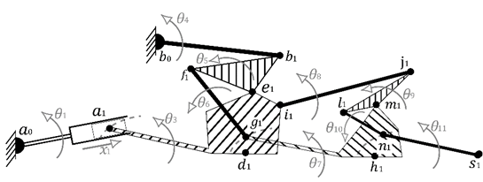
The kinematic analysis is performed using a special case of rotational displacement matrix (2D path) proposed by Suh and Radcliffe32. The mechanism has twelve bodies and sixteen joints; therefore, it has one degree of freedom (DOF). System variables are shown in Figure 3, the angles θ1 to θ11 represent the angular orientation of the respective body and x1 represents the displacement of the linear actuator.
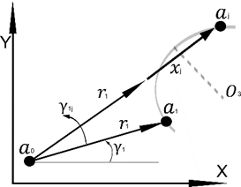
Figure 4 shows the vectors (r_n) associated to the mechanism at initial positions, where:

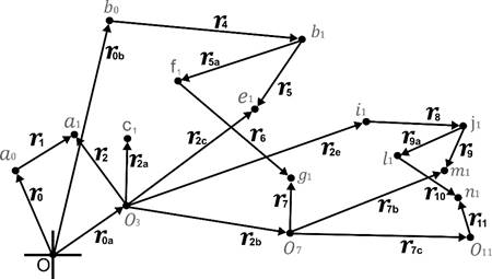
Because the mechanism has 1 DOF and 11 variables (according the Grübler-Kutzbach criterion), it is necessary to create 5 loop equations. Equations (1) to (5) represent the mechanism loops in any position or time. In these equations
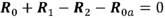 (1)
(1)
 (2)
(2)
 (3)
(3)
 (4)
(4)
 (5)
(5)
In the above equations, vectors with subscript n=2,3,4,5,5a,6,7,8,9,9a,10 and 11 have only a rotational movement, therefore their position Rn can be calculated by using the rotational displacement matrix for a 2D path given in equation (6).
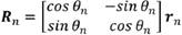 (6)
(6)
Vectors, r0 , r0a and r0b do not change their positions, because they are defined between two fixed points, therefore:
 (7)
(7)
 (8)
(8)
 (9)
(9)
Vector R1 has rotational and longitudinal movements, equation (10) defines its movement.
 (10)
(10)
Optimal Synthesis of Mechanism
Besides the design factors, the synthesis includes more restrictions: the mechanism must follow the flexion-extension path of each phalanx (see Figure 1); dimensions of mechanism should not interfere with flexion-extension finger movement; linkages paths should not interfere with each other; mechanism must reach maximum flexion angles of each phalanx (70°, 90° and 50° for proximal, medial and distal, respectively, based on Cynthia and Joyce31 the authors consider these values are sufficient to perform any grasp task). We establish that the mechanism must pass through five positions (control points) from a fully extended to a fully flexed position.
The synthesis of mechanism is realized using the matrix method proposed by Suh and Radcliffe32, in which a plane displacement matrix is designated for some bodies of the mechanism; each matrix include a rotational angle, these angles are shown in Figure 5 and represent the rotation of the correspondent body. For example β1j is the angle that the body 5 (see Figure 2) generates when it moves from the position 1 to the position j. Hereinafter, subscript or superscript j will represent any future position. One of the advantages of this method is that the results are always in the real number space.

The synthesis of mechanism starts at point d1 (see Figure 5), a plane displacement matrix
 (11)
(11)
In this paper all plane displacement matrices will be abbreviated as
Using the matrix
Using the ij point it is possible to create the matrix
Following this procedure all plane displacement matrices of this mechanism are set. For the body 9,
Input actuator (bodies 1 and 2) has both rotational and lineal movements. Figure 6 represents the movement of the point
Equations for synthesis of rigid links
Restrictions of the mechanism are provided by equation (12) that is established for rigid links; therefore, the magnitude of the distance between all points of the same body will not change during the movement of the mechanism. For example, equation (f 1-g 1)T(f 1-g 1)-(f j-g j)T(f j-g) = 0 represents the fact that the link longitude of the rigid body (f 1-g 1) in the initial position is the same that longitude in position two (f 2-g 2) and so on. The first objective function can be written as equation 12, where
 (12)
(12)
Equations synthesis of semicircular slider
Orthosis mechanism is formed by three sliders, each one with a semicircular path, with the center of rotation coincident with the joint of the respective phalanx (bodies 3, 7 and 11). The equation of a circumference centered at the point (O3x, O3y) is used to develop an equation for the synthesis of semicircular slider for the body 3:
 (13)
(13)
Due to the fact that the radius r is constant during the whole slider trajectory, the equation for the j position is
 (14)
(14)
The other semicircular paths (bodies 7 and 11) can be obtained in a similar way. The objective function for all semicircular sliders can be written as:
 (15)
(15)
Additional restrictions for the synthesis
Due to some problems of interference between adjacent links, bodies 5 and 9 need to be straight links, the equation (17) is obtained through the dot product property and are necessary to achieve such condition.
 (16)
(16)
It is necessary that the mechanism reaches the maximum flexion angles ϕ and ψ at medial and distal phalanxes, respectively. The equation (18) is established to fulfill this condition:
 (17)
(17)
For this mechanism and its restrictions there is no exact solution; it is then necessary to perform an optimal synthesis. The global objective function F(Χ) is formed by F(Χ) = F1(Χ) + F2 (Χ) + F3(Χ) + F4(Χ). The results presented below correspond to the solution of this Objective Function.
Results
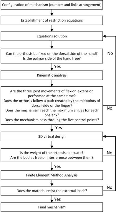
The process to find an optimal mechanical design is iterative; the synthesis equations do not guarantee that all specifications will be satisfied, because these equations do not include the interference between adjacent links or the continuity on the mechanism movement, for instance. The iterative process consists on synthesizing one mechanism, then performing a kinematic analysis and verifying that the mechanism fills all other design factors. After several iterations, the mechanism that satisfies design factors and specifications is found. The process of design the mechanism is shown in Figure 7.
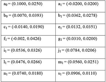
Coordinates, in meters, of all points of the mechanism are presented in Table 1.
The virtual design of the optimal orthosis we are interested in is presented below.
Virtual Design and Prototype Manufacturing
Values obtained through the synthesis are actually in 2D, a Computer-Aided Design software was used to make a 3D virtual model, in which the rest of all design factors is considered. The virtual model of the orthosis is presented in Figure 8. As the reader can see, our prototype will be placed on the dorsal side of the hand and easily be adapted to any of the fingers. The most important feature of the 3D model is that there should be no interference between any of its components, during the all flexion-extension movement.
All links of the mechanism were manufactured using a mini 3-axis CNC mill. All the joints were made using cylinders of steel commercial of 2 mm of diameter pressure-mounted. Clearance of mobile parts are approximately 0.1 mm.
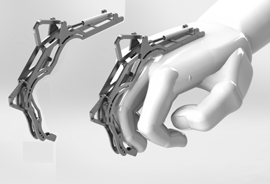
Figure 9 shows our first orthosis prototype in a fully extended position. The mechanism weight is 0.3531 N (without actuator), it has a length of 16 cm and it is 3.2 cm high; therefore, the size and weight are adequate to be used by a person during all day. A possible actuator can be a standard miniature linear motor, which must be mounted between the points a0 and a1.
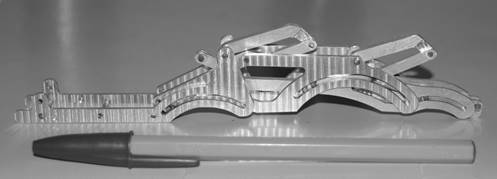
Figure 10 shows three pictures of our first orthosis prototype mounted on the middle finger of a human hand. As the reader can see, the orthosis is placed only on the dorsal side of the hand, this featured permits the user to perform the ADL without orthosis interference.

Conclusions
In this paper a novel mechanical design of a finger orthosis is presented. An optimal synthesis of this orthosis is performed, necessary to satisfy all design factors. The design process is iterative because with the synthesis alone it is not possible to ensure that all requirements are satisfied. The final mechanism has 12 rigid links and 1 degree of freedom, that make possible to flex the three phalanxes at the same time and to activate a greater amount of muscles of the finger; to the best knowledge of the authors, for a finger orthosis these features have not been reported until now.
Three semicircular sliders are used with a new and simple way to synthesize them. We found that this element type, unlike straight sliders, reduce considerably the mechanism size for applications with semicircular movements. A first physical prototype has been manufactured to perform experimental tests as future work.
Mechanism synthesis is performed considering the size of an adult male between 18 and 64 years old, within the percentile 50 of the Mexico City's population. All the orthosis movements considered in this project are based on a natural finger movement; therefore, it is possible to replicate the same mechanism for other fingers, even for other hand sizes, it is only necessary to make an adjustment on the scale of each element. The size and weight of the final prototype are adequate to be used by a person during a common day. The mechanism does not interfere with the palmar side of the hand; therefore, the user can perform the Activities of the Daily Living while is being rehabilitated.

