


 nueva página del texto (beta)
 Inglés (pdf)
 Artículo en XML
 Referencias del artículo
 Enviar artículo por email
 Citado por SciELO
  Similares en
SciELO
Similares en
SciELO 
 Permalink
INTRODUCTION
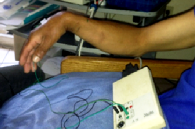
The radial nerve is one of the most important nerves in the human body. It is the responsible for the sensitivity of the back-side and side of the arm and forearm, the dorsal wrist and hand, and the first four fingers, of the extension and supination of the forearm, hand and fingers. For a more detailed description of the radial nerve anatomy, see [1, 2]. The superficial branch of the radial nerve (SBRN) is the third most commonly damaged peripheral nerve and is readily amenable to repair. Injury may result from fractures, lacerations, sustained pressure or may be iatrogenic [2]. These injuries can cause a loss of sensation and motor functions of the hand, see Figure 1. It is necessary to perform rehabilitation for the hand to regain previous dexterity. Currently, most rehabilitation activities are performed manually by physiotherapists. However, this involves high personnel costs and the lack of motivation from patients to perform exercises [3].
According to data from a World Bank report about disability [4], one billion people, or 15% of the world’s population, experience some form of disability, and disability prevalence is higher in developing countries. Among them are a large number of people with motor disabilities. This renders rehabilitation a primary challenge with the goal of helping and improving the quality of life for patients by using new technologies in rehabilitation centers. In recent years, one of the trends in robotics and mechatronic engineering has been the development of medical devices, especially for physical rehabilitation tasks [5, 6, 7]. Today, the concept of “rehabilitation robot” may include a wide array of mechatronic devices ranging from artificial limbs to robots for supporting rehabilitation therapy or for providing personal assistance in hospital and residential sites [8, 9]. In particular, rehabilitation robots for hand and wrist injuries can be divided into three groups: prosthesis [10, 11], exoskeletons [3, 12, 13] and non-anthropomorphic devices [14,15,16,17,18,19]. The device developed for this paper belongs to the third group.
Kawashi et al. [14], developed a robot assistant with 18 degrees of freedom (DOF) for rehabilitation therapy. The robot has a self-motion control, which allows the impaired hand of a patient to be controlled by his or her healthy hand on the opposite side. The hand motion robot assistant is designed to support the flexion/extension and abduction/adduction fingers and thumb motions of independently as well as the opposability of the thumb. One of the requirements of this device is that patients must have a healthy hand to control the robot assistant. Khokhar et al. [15] presented the design, control and testing of a rehabilitation/assistive device for the wrist flexion/extension and ulnar/radial deviation. This mechanism has 2 DOF and uses electromyography (EMG) signals to identify the user’s intention and helps with the movement of the hand by supplying the assistive force. The authors propose testing the device with real patients as a future work. Kim et al. [16] present the design and manufacture of a wrist rotation rehabilitation robot based on force measurements for severe stroke patients. The device has only 1 DOF (the wrist rotation) and it can be used only on patients lying in bed wards. A robot called the Closed-chain Robot for Assisting in Manual Exercise and Rehabilitation (CRAMER) was developed by Spencer et al. [17]. The CRAMER uses a parallel mechanism to assist in 3 DOF wrist and forearm exercises. In order to keep the low cost of the device, the authors use hobby servomotors and they propose using the Nintendo Wii to complement rehabilitation tasks. Williams et al. [18], presented a pioneering clinical result which suggest that robot-aided neurorehabilitation can have a positive influence on neuro-recovery following a stroke. Recently, Squeri et al. [19] have shown the efficiency of a robot-based therapy for upper limbs. The therapy is based on movements with slow oscillatory patterns of small amplitude and progressively increasing bias, in order to maximize the recovery of the active range of motion.
The developed movements by the mechatronic system are flexion/extension of the wrist and flexion/extension of the hand fingers from the metacarpus. The device is based on two coupled four-bar mechanisms. Each mechanism drive (DC motor) has a Proportional-Integral-Derivative (PID) controller to regulate the rotational velocity. In addition, touch sensors are used to limit the mechanism’s movement. The implementation of the control algorithm and the logic to perform the synchronized movements are performed by an ATMEGA 16 microcontroller. The result is an affordable and functional prototype which needs to be tested in real situations with the help of physiotherapists and patients to obtain the necessary information to improve its performance.
As previously stated, disability prevalence is higher for developing countries. Moreover, the commercial rehabilitation devices are expensive and are usually, they are unaffordable for public health institutions. In this work the design, analysis and implementation of a mechatronic System focused on helping to improve Rehabilitation therapies for patients affected by some Radial Nerve Injuries (SYRR-NERI) are presented.
METHODOLOGY
Mechatronic design of the SYRR-NERI
The device proposed in this work belongs to the embedded system category, therefore, in order to develop it, the SPIES methodology [20] was considered. The use of this methodology enables proper system maintenance and facilitates the system upgrade. Figure 2 shows the SPIES methodology applied to the development of the mechatronic system proposed in this work.

The SPIES methodology begins with requirements specifications of the system to be built (phases 1 and 2). In the next phase, a conceptual design of the system must be carried out; this phase is focused on two system issues: functional design and architectural design. Phase 4 complies with the system implementation. In order to optimize this task, the system is divided into three subsystems: mechanical, hardware and software. Therefore, the subsystems can be developed concurrently. In Phase 5, activities that form the subsystems are developed, including basic tests to determine the correct coupling between the subsystems. The validation phase includes extensive field testing for determining the correct operation of the embedded system. Finally, the embedded system is ready for delivery. The following sections describe the most relevant details of these phases.
Specifications
In order to obtain the design specifications for the mechanism, we attended some therapy sessions and the physiotherapist determined that for the rehabilitation of a typical injury in the superficial branch of the radial nerve, the therapy consists of manual or electrically induced repetitive movements. The cycles are hand extension/flexion with amplitude on the order of 60° in about 3 s, see Figure 3. In addition to hand movement, synchronized finger movement is also necessary, for example movement cycles such as hand extension/fingers extension/fingers flexion/hand flexion. Moreover, the device must be compact, portable and affordable.

Mechanical subsystem
Due to the desired movement, a plane mechanism is considered because of its simplicity over a spatial mechanism. The four bar mechanism was chosen because it is one of the simplest solutions for movement in a plane [21]. Two coupled four bar mechanisms were proposed (Figure 4a). The extension/flexion movement of the hand is carried out by the link 4 of the mechanism 1, see Figure 4b, while the movement of the fingers is developed by the link 4 in mechanism 2, Figure 4c.

FIGURE 4 Coupled four bars mechanisms. a) Both mechanisms in their initial position. b) First mechanism with hand extension movement. c) Second mechanism with fingers extension.
The mechanisms synthesis was based on the analytical procedure described in [21] taking into account the average dimensions of the hand and forearm of a Mexican adult [22]. The links dimensions are shown in Tables 1 and 2.


The degrees of freedom (DOF) for each mechanism were calculated by the Gruebler equation [21]
where M is the number of DOF, n is the number of links, j p is the number of main joints (revolute, prismatic) and j h is the number of superior order joints (gears, cams).
Applying Equation (1) to each four bars mechanism with n= 4, j p = 4 and j h = 0, it can be determined that the number of DOF for each mechanism is equal to one.
Moreover, the Grashof condition given by Equation (2) was verified for each mechanism.
where S is the shortest link length, L is the shortest largest link length, P and Q are the other two links length.
According to the data in Tables 1 and 2, both mechanisms are Grashof which means at least one link is able to rotate 360° with respect to the fixed reference.
Position, velocity, acceleration and forces analysis for the designed mechanisms were carried out analytically by Matlab based on procedures described in [21] and the obtained results were corroborated by simulations of the mechanisms in Solid Works. In this work, only the results for the first mechanism are presented. For a more detailed information see [23].
Position analysis consists of obtaining the angles θ 3, θ 4 and γ from the input angle θ 2 and the known links length, see Figure 5.

Position equations for a closed four bar mechanism are given by Equations (3), (4) and (5) [21].
where a is the length of link 2, b is the length of link 3, c is the length of link 4 and
In Figure 6, the angular positions as a time function for mechanism 1 are shown. As can be observed in Figure 6a, a constant angular velocity is considered as the mechanism input. Velocity equations for a closed four bar mechanism are given by Equations (6) and (7) [21].

FIGURE 6 a) Angular position of the input link of mechanism 1. b) Angular position of the coupler link of mechanism 1. c) Angular position of the output ink of mechanism 1.
where ω2 is the angular speed of link 2, ω3 is the angular speed of link 3 and ω4 is the angular speed of link 4.
In Figure 7a the angular velocity of the output link of mechanism 1 is presented. To verify these results, the mechanism movement was simulated in Solid Works. The results for angular velocity of the output link of mechanism 1 is shown in Figure 7b. As can be observed, the results obtained from Solid Works are consistent with those found with Matlab. The acceleration analysis was carried out using Equations (8) and (9) [21]. Results for links 3 and 4 are presented in Figure (8).

FIGURE 7 a) Angular velocity of the output link of mechanism 1. b) Angular velocity of the output link of mechanism 1 obtained with Solid Works.
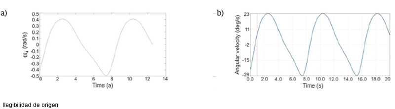
FIGURE 8 a) Angular acceleration of the output link of mechanism 1. b) Angular acceleration of the output link of mechanism 1 obtained with Solid Works.
where α2 is the angular acceleration of link 2, α3 is the angular acceleration of link 3 and α4 is the angular acceleration of link 4.
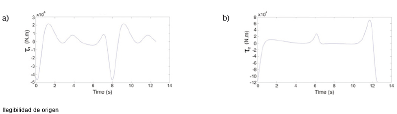
The dynamic forces analysis was carried out by the matrix method described in [24]. Through this analysis, the forces in the mechanism connections and the torque required to perform the movement considering the external load are obtained by solving the following Equation
where rij is the mass center vector of the link i referenced to joint j, Fik is the force of the link i over the link k, Mi is the mass of the link i, Agi is the mass center acceleration of the link i and Ii is the momento of inertia of the link i.
The interconnection forces Fik are used to design the connector between the mechanisms links. The obtained torques Ts are taken into account when selecting the driver motors for each mechanism. In Figure 9 the calculated torques for both mechanisms are shown.
Hardware and software subsystem development
The features offered by microcontrollers meet the needs of the proposed system in this project. Therefore, SYRR-NERI is a microcontroller-based embedded system. Due to the close relationship between hardware and software subsystems of this type of system, this section describes both subsystems together. In this paper, this union is referred to as Subsystem of Processing and Control. Figure 10 shows the main components that make up the Subsystem of Processing and Control, and the relationship between them. These components are grouped to form modules that perform a specific function. Therefore, this subsystem is comprised of four modules: Central processing device, User interface, Motor control and Position detection. Each of these modules includes a hardware section and a software section. Determining the current position of the mechanical subsystem of SYRR-NERI is carried out by the Position detection module. To this end, this module has two snap action switches per motor, SAS={SAS4,SAS3,SAS2,SAS1}, see Figure 10.

Thus, the position of mechanical subsystem is indicated by status of these elements and considering the system trajectory, only five states can occur. The Position sensor driver component includes hardware that monitors the SAS status. When an event occurs, this information is passed on to the Position detection component through an external interruption. In response, the SAS status is determined, then it is encoded and transmitted to the Motor control module through s3, s2 and s1 signals. Table 3 shows the sequence of SAS states generated for one work sequence of the mechanical subsystem. Furthermore, the code for each SAS status is also shown. The F2 variable is used to ensure proper mechanical subsystem trajectory.

Finally, the most complex module is described, the Motor control, see Figure 10, which is responsible for the proper functioning of the mechanical subsystem. The hardware section of this module is composed of two 12 V, 100:1 gear motors with encoder (M1 and M2), whose function is to move the mechanical subsystem and the Motor driver, which includes logic to decode the information from the Motor control component and define the motor’s behavior (see Table 4) and a quadruple high-current half-H driver L293-B, used to provide bidirectional drive current to both motors. Meanwhile, the Motor control component is designed to fulfill two functions: 1) manage the movement of mechanical subsystem, and 2) ensure a smooth, stable and constant motor speed.

First, every time the system is powered or rot signal is activated, the Motor control l executes a routine placing the mechanical system in its initial position, where both SAS1 and SAS2 are active (s3, s2, s1 code is “000”). Furthermore, this component performs a work sequence when C signal is active and indicates the end of this task by activating the ws_ok signal.
In order to generate the mechanism movements that complete a work sequence, the component is based on s3, s2 and s1 signals to determine which motor must work and its rotation direction; this information is transmitted to the Motor driver via the En, Rot and M signals.
Moreover, to fulfill the second function, the component implements a Proportional-Integral-Derivative (PID) controller to minimize the error over time by adjusting the motor speed.
The output of a PID controller, in the time-domain, is defined as:
where u(t) is the control signal, e(t) is the tracking
error
In order to implement a microcontroller-based PID controller it is necessary to obtain a discrete approximation of Equation (11). Then, applying the Euler method [25, 26], the discrete approximation of continuous integral
defined as
where Δt is the step of integration (interval of time from tn to tn+1 and
On the other hand, the finite differences method of the first order [27] using the backward difference is used to obtain the discrete approximation of continuous derivative. Then, the discrete approximation of de(t)/dt is defined as
where
Based on Eq. (12), the PID controller
implementation on ATMEGA16 microcontroller was carried out. Where Kp=
0.095, Ki= 1.784 and Kd= 0.001 and, in order to ensure the
proper functioning of the mechanical subsystem, the motors must work at a
constant speed of 18 rpm (
Finally, as the motor speed control is produced by PWM technique, the result of the PID controller is delivered to a 16-bit PWM implemented with another microcontroller Timer, which generates the PWM signal, with an approximate frequency of 116 Hz, delivered to the Motor driver.
RESULTS
In this section, the manufacturing and assembly process for the SYRR-NERI is described. The machining of the parts was made on CNC machines using different materials such as nylamid, acrylic, polyvinyl chloride and palight. It is important to mention that the machining and assembly processes were carried out in their entirety within the facilities of the Universidad Tecnológica de la Mixteca. In Figure 11 some stages of the manufacturing and assembly process are shown. For more details about the construction of the prototype, see [23].

FIGURE 11 Manufacturing and assembly of the SYRR-NERI. a) Machining in CNC milling. b) Subassembly of the structural base with motor and electronic components. c) Mechanism and motor assembly.
In Figure 12 the final prototype of the SYRR-NERI is shown, and finally, in Figure 13 a half work sequence of the SYRR-NERI is illustrated. As can be observed, the sequence is hand extension/fingers extension, which is according with the specifications.


FIGURE 13 A half work sequence of the SYRR-NERI. a) Initial position. b) Hand extension. c) Fingers extension.
The closed loop performance of SYRR-NERI can be observed in an online video [28].
CONCLUSIONS
In this work, the development of a mechatronic SYstem to improve Rehabilitation therapies to patients affected by Radial NErve Injury (SYRR-NERI) was presented. The SPIES methodology for embedded systems was used to enable a proper system maintenance and to facilitate the system upgrade. Simple and affordable solutions were proposed for different subsystems. The mechanical subsystem was based in two coupled four bar mechanisms driven by DC motors with a PID control for angular velocity. The control scheme was implemented by an ATMEGA 16 microcontroller whose programming was described in detail. The user interface was implemented by two 7-segmet displays and a simple 4 button keypad in order to allow the user to indicate the number of times that SYRR-NERI must repeat the work sequence, and for stopping or interruption of the SYRR-NERI operation. The resulting system is a functional prototype completely designed and built in the Universidad Tecnológica de la Mixteca. Field testing supervised by a physical therapist in order to get information that allows us to make modifications to improve the SYRR-NERI performance are proposed as future works.

