


 nueva página del texto (beta)
 Inglés (pdf)
 Artículo en XML
 Referencias del artículo
 Enviar artículo por email
 Citado por SciELO
  Similares en
SciELO
Similares en
SciELO 
 Permalink
1. INTRODUCTION
For telescopes composed of two mirrors, the zero coma point (ZCP) determines a physical point over the optical axis of the primary mirror, M 1, where the secondary mirror, M 2, can rotate during the collimation process, without introducing transverse coma in the resulting image. The analytical expression for the ZCP in aplanatic reflector telescopes is well known and it is of great importance in the alignment of classical telescopes, such as the Cassegrain, Gregorian or Ritchey-Chretien type (Schroeder & Inc 2000; Schechter & Levinson 2011); however, this equation is not directly applicable to some variants of widefield reflector telescopes, composed not only of conical surfaces but also containing asphericity terms in the secondary mirror, or telescopes coupled with aspherical corrective lenses.
In the present work, we developed an exactray-tracing algorithm for off-axis aspherical surfaces, which we applied to the numerical determination of the ZCP for classical and non-classical telescopes. As an example of the application of this algorithm, we show the calculation of the ZCP for every telescope of the Observatorio Astronómico Nacional (OAN-SPM), which is located in the Sierra San Pedro Mártir, Baja California, México.
The content of this article is divided as follows: in § 2 we describe the analytical solution and how it is used in the collimation process; in addition, the concept of the ZCP is described. § 3 describes the concept of non-classical design for a telescopes with asphericity terms in one or more surfaces of the system. In § 4 we describe the transverse coma aberration by means of three rays traveling through the surfaces of the telescope, given that this process will be the basis for the function to be minimized using our proposed algorithm. In § 5 we describe the approach required for programming the general ray tracing function, using off-axis arbitrary surfaces. We include flowcharts representing the complete algorithm procedure in § 6, while in § 7 we discuss the spot diagrams and output plots for a theoretical wide-field telescope used as an example of the aplication of our algorithm. In § 8 we present the values of the ZCPs for the telescopes of the OAN-SPM and future projects under development. Finally, we present our conclusions in § 9.
2. CLASSICAL ANALYTIC SOLUTION
An aplanatic telescope composed of two mirrors with conical surfaces enables the possibility to correct the spherical aberration in an exact form or, at least, a correction to third order. While the powers of both surfaces allow us to balance and control the Petzval field curvature and define the system’s power, the conic constants allow us to control the spherical aberration, in the case of a Cassegrain telescope. However, with the improvement in the construction precision of conical surfaces of revolution, we have been able to reduce an additional optical aberration, typically, the coma.
A reflector telescope with a laterally misaligned or inclined element becomes an optical system without symmetry of revolution; this means that the optical axis is no longer coaxial with the mechanical axis, which in turn produces a displacement of the exit pupil that originates coma arising from misalignment. The nature of this induced aberration has been widely studied, for example by Schroeder & Inc (2000) and Schechter & Levinson (2011); the latter present an exhaustive analysis of the patterns generated by misalignment. The understanding of these effects is of special relevance, since real-world telescopes are opto-mechanical systems subject to mechanical bending and misalignment.
A problem associated with the misalignment of reflecting telescopes is that it is impossible to unequivocally determine the origin of axial coma, as it can be originated due to lateral displacement, inclination of the secondary mirror, or a combination of both. The misalignment produced by displacement and inclination can even be of the same magnitude and of the opposite sign (Schroeder & Inc 2000), which allows the effect to be compensated and eliminated. In a misaligned system, astigmatism is asymmetric and linear in the field; this is added to the natural astigmatism due to optical design or astigmatism produced by the shape of the elements, either by construction or by errors in the support of the optical components.
In the collimation process of a telescope we look for the coaxiality of all the optical elements. A very useful collimation procedure is described by McLeod (1996). Prior to achieving an optimal collimation, the image plane of a slightly out-of-focus telescope exhibits donut-shaped images, which will be defocused and will display astigmatism and coma.
Typically the aberration of astigmatism is not a problem in nearly collimated telescopes, where the coma dominates the image quality. In this case, it may be sufficient to correct the coma by means of only lateral displacement or tilt of the secondary mirror. However, our main interest in this work is the collimation of wide-field telescopes, for which the astigmatism at the edges of the wide field will be more relevant than in small-field telescopes.
In the first collimation stage, we compensate the axial coma aberration by means of lateral displacements of the secondary mirror, until the image plane is dominated only by astigmatism. When the optical systems are aligned, the astigmatism is distributed with symmetry of revolution over the entire field, or it can be zero depending on the design of the system. There are strategies to measure the wavefront around the field to estimate the tilt or shift of the secondary mirror required to correct the astigmatism (McLeod 1996). However, this correction should not introduce coma aberration again.
For this reason, it is important to perform continuous compensation of astigmatism, by simultaneously moving and tilting the secondary mirror. This combination is homologous to move the secondary mirror, with its optical axis pivoting around a single point on the optical axis of the primary mirror. This point is known as the “zero coma point”, also called “neutral point”, which has been calculated in different ways by several authors; one of the most cited works is that of Schroeder & Inc (2000). Thus, by moving the secondary mirror with respect to this point, we avoid inducing axial coma in the image plane, when trying to compensate for astigmatism.
It is important to point out that, before starting any movement with respect to the ZCP, we must first reach the compensation of coma during the first collimation stage, as described before. Once this is achieved, we guarantee that the optical axes of the secondary and primary mirrors are aligned. Then, the analytical equation to calculate the position of the ZCP is determined for the third order correction, according to equation 1 (Wetherell & Rimmer 1972):
where ZCP is the distance to the zero coma point measured from the secondary mirror, C M2 and K M2 are the secondary mirror’s curvature and conic constant, and m = F/F p is the amplification of the system.
3. NON-CLASSICAL TELESCOPES
There is, however, a caveat to the previously described procedure. There are telescopes that are composed of conical surfaces plus an asphericity polynomial term α j . Other telescopes also contemplate one or more correcting aspherical lenses, whose sagittae are defined according to equation 2:
where z is the sagitta of the surface, s 2 = x 2 + y 2 is the distance of the optical axis to a point over the surface, K is the conic constant and c = 1/R c is the paraxial curvature, with R c the radius of curvature of the surface.
As expected, equation 1 for the ZCP is not appropriate for telescopes with these aspheric components. The objective of this work is to numerically determine the position of the ZCP in the most general way, given that corrective lenses can have different contributions in the correction of aberrations and an analytical estimation of the ZCP can rapidly grow in complexity, as we increase the number of surfaces to be considered.
4. COMA-INDUCED CHANGE IN AMPLIFICATION
There are several procedures to evaluate and compensate the axial coma, such as the Abbe sine condition and the offense against the sine condition (OSC) (Smith 2000). There are also general forms for Abbe’s sine condition that contemplate systems without symmetry of revolution (Elazhary et al. 2015). However, the transverse coma aberration does not require the calculation of the position of the system’s exit pupil, which is defined as the change in amplification as a function of the aperture (see Figure 1), expressed as:

Fig. 1 Transverse coma produces a different amplification for the same object with a dependence on the system’s aperture. The color figure can be viewed online.
In Figure 1 we can see three rays arriving on a meridional plane, two of them, R ma and R mb , are passing through the edges of the pupil of the system and the third ray is passing through the center of the pupil, called the principal ray R p . From the exact ray tracing we can find the direction cosines of these three rays and the intersection point on the surfaces. With this information we can determine the point of intersection between rays R ma and R mb , we can find the distance from this point to the optical axis, the position of the perpendicular plane to the optical axis passing through this point and, finally, the point of intersection of the principal ray R p and its distance from the optical axis.
5. COMA COMPENSATION FUNCTION
The evaluation of the aberrations of an optical system can be done based on the exact ray tracing procedure, which determines the optical path of a ray passing through a set of surfaces. The exact ray tracing, is also known as “skew ray tracing” (Spencer & Murty 1962).
Taking advantage of the procedure for calculating the ZCP and using the exact ray tracing described in § 4, we programmed a function in Python for calculating the exact ray tracing through a telescope that has a correcting lens. In this program it is possible to define the conic and asphericity parameters as constants. With this routine, it is also possible to introduce lateral displacements on the secondary mirror. As a result of this program, we can calculate the parameters of the three rays at the output of the system, as schematically described in Figure 1 and Figure 2.

Fig. 2 Output ray parameters used in the evaluations of equations 4, 5 and 6, that help us to compute the transverse coma. The color figure can be viewed online.
With the parameters of the marginal rays R ma and R mb we can calculate the point y m , where the vectors intersect, and also the height of the chief ray y p :
With these parameters we are able to calculate the transverse aberration, described by equation 3. Solving by the Newton-Raphson method for the tilt value of the secondary mirror that minimizes the transverse aberration, we have:
6. SOS-ZCP ALGORITHM
The SoS-ZCP (Serpent of Stars-Zero Coma Point) is an algorithm written in Python, divided into three sections in terms of its functionality. The first section incorporates the thorough General ray tracing function for a three-dimensional continuous surface. In this script the user provides the surface properties and position (tip/tilt and shift) in space; therefore, this part of the algorithm can be used as an operator that is supplied with a ray and then returns the ray parameters through the entire system. The ray is provided as a data set with the origin coordinates and direction cosines, the returned data are in the same format. The function is configured with all the telescope parameters, surface by surface, including corrector lenses if they are required.
The second section of the algorithm invokes the first function to trace the three rays presented in Figure 2. Using equations 4, 5 and 6 the coma aberration is calculated, by means of equation 3. It is important to mention that, in this second part of the algorithm, the user can modify the properties of the system, such as the tilt and shift of an element.
The third section of the algorithm (schematically described in Figure 3) takes the output of the second section and uses it as a function of two variables, T x and θ y , which are the secondary mirror M 2 lateral translation and tilt angle, respectively.
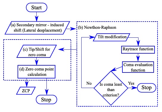
Our algorithm applies the Newton-Raphson method in an optimization process, in order to calculate the value of θ y that minimizes the amount of coma, then setting a criterion near to zero (1e-7 mm), for a proposed translation T x of M 2. The projection of the resulting compensated M 2 optical axis on the M 1 axis is calculated directly from the triangle defined by the lateral translation and tilt; thus, the ZCP is calculated as:
The source code of the SoS-ZCP is available at https://github.com/MNajeraR/SoS-ZCP (Nájera et al. 2021). It is implemented in Python 2.7 under the MIT License. Version v2.0.0 is used in this paper and is archived at http://doi.org/10.5281/zenodo.4929555.
7. WIDE-FIELD TELESCOPE EXEMPLIFICATION
We are especially interested in calculating the ZCP for a telescope similar to those of the TAOS-II project, given that they will have an aspheric secondary mirror and a very wide field of view (FOV = 1.7o), which is the ideal scenario for this implementation. The parameters of the TAOS-II telescopes are not yet public. However, the manufacturer has provided all the information for the commercial telescopes (Melsheimer & MacFarlane 2000; Bowen & Vaughan 1973), which we have used to design our example telescope.
We have designed a theoretical f/3 telescope, whose primary mirror is 2.1 m in diameter and has a FOV = 1.4◦. The primary and secondary mirrors have the same radius of curvature to decrease the Petzval curvature, the system has an aspherical correction plate and the secondary mirror also has an asphericity term. The parameters of the design data are listed in Table 1.
TABLE 1 TELESCOPE φ 2.1m f/3 (THEORETICAL EXAMPLE)
| Element | Radius (mm) | Thickness (mm) | Glass | Semi-Diameter (mm) | k | α1 | α2 | α3 |
| M 1 | −7670.112 | −227241 | Mirror | 1005.0 | −1.597 | |||
| M 2 | −7670.112 | 227241 | Mirror | 465.0 | −37.027 | 5.940e−19 | ||
| M 1 Vertex | 56.538 | Air | ||||||
| Corrector Front | 7.0 | Silica Schott | 191.0 | 3.955e−5 | −1.021e−9 | |||
| Corrector Back | 300.0 | Air | 191.0 | |||||
| Image Plane | 78.4 |
In order to calculate the zero coma point for this telescope, we introduced its parameters in our algorithm. We calculated the position of the ZCP at a distance of 564.8 mm, behind the secondary mirror. In Figure 4 we show an schematic diagram of the telescope, with the secondary mirror rotated by 0.1◦, pivoted around the ZCP. In Figure 4 we only show the two marginal rays and the principal ray; they are parallel to the optical axis. At the image space these rays converge to the same off-axis point, minimizing the coma. For rays arriving in a meridional plane (x, z) the convergence occurs at a point on the chief ray; for rays incident on the sagittal plane (y, z) the converging point on the chief ray is different, which is the physical origin of the astigmatism.

Fig. 4 Wide-field telescope example. The three parallel rays converge to the same point, when M 2 is pivoting around the telescope’s ZCP, located at 564.8 mm behind the secondary mirror. The color figure can be viewed online.
Figure 5 (left) shows a set of 9 spot diagrams for different fields on the image plane of our widefield telescope, in this case the telescope is perfectly aligned and focused. The wavelength used for the present example is 600 nm. The spot diagrams were made with a polar-array ray pattern (Malacara-Hernández & Malacara-Hernández 2013) in the entrance pupil M 1, where a slight astigmatism aberration is perceived, especially in the corner images, which is not related to the scale of the plots. In Figure 5 (right), coma aberration can be clearly seen over the entire field. In this example the secondary mirror M 2 is laterally displaced by 1 mm outside of the optical axis, without adding tilt.

Fig. 5 Spot diagrams for a wide-field telescope, (left) aligned telescope, (right) with introduction of a 1 mm lateral displacement in the secondary mirror, where the coma aberration is evident.
Figure 6 (left) shows the spot diagram produced by the same system as Figure 5, but this time a pivoting movement has been made with respect to the ZCP. The image plane has been slightly put out of focus to allow the images to display the typical annular shape produced by out-of-focus telescopes. These spot diagrams display astigmatism aberration (Z 22 from Zernike polynomials) that can be estimated using equation 9 (Luna et al. 2007), which is not symmetrical in the field:
where A and B are the major and minor axes of the ellipse produced by astigmatism. It is important to stress that, when pivoting around the ZCP, coma aberration is not added to the field.

Fig. 6 Spot diagrams for a wide field telescope. (Left) with pivoting of the secondary mirror with respect to its ZCP. The images are out of focus to show annular images. (Right) spot diagrams at the correct focus. In both diagrams we can see the presence of astigmatism and very little coma contribution, given that the original design has a small coma aberration.
Figure 6 (right) shows the same spot diagrams as those on the left, but with the correct focus; we can see from the scale that, even when using focused images, it is not possible for us to accurately evaluate the amount of astigmatism when performing collimation, specially under bad seeing conditions. Therefore, the correction of astigmatism must be done in fine alignment using a wave-front sensor.
In Figure 6, the small proportion of spherical aberration is due to the presence of spherical aberration in the design of the primary mirror, because it was not completely corrected. The aberrations produced by misalignment are only coma and astigmatism, where the proportion of induced astigmatism depends on the particular design, which must be considered in each case.
It should be noted that the spot diagrams were made with the same function programmed for the exact ray tracing (General ray tracing function). This is a by-product of the present work, which can be used, modified and applied to various other academic problems, such as the optimization of the parameters of an optical design, by direct use of a particular ray aberration as a merit function.
8. OAN-SPM TELESCOPES
We calculated the ZCP for every one of the classical telescopes of the OAN-SPM, using the analytical expression, together with the numerical results obtained with our algorithm for comparison. Additionally, we have included the 2.12 m telescope of the Observatorio Astrofísico Guillermo Haro located in Cananea, Sonora, México. In order to perform this calculation, we need the construction parameters of the telescopes, which are presented in Table 2, where the SAINT-EX and TAOS-II telescopes have been omitted, because their parameters are not yet public.
TABLE 2 CONSTRUCTION PARAMETERS FOR OAN-SPM TELESCOPES
| Telescope (m) | Focal ratio f/# | Mirror | Rc (mm) | Thickness (mm) | k | Diameter (mm) |
M1 Vertex to Image plane (mm) |
| 0.84 | 15 | M 1 | −5287.0 | 2029.7 | −1.0049 | 840.0 | |
| M 2 | −1555.0 | 877.1 | −2.6990 | 250.0 | |||
| 1.5 | 13 | M 1 | −5975.0 | 2475.7 | −1.0049 | 1540.0 | |
| M 2 | −1208.0 | 877.1 | −1.8970 | 275.0 | |||
| 2.1 | 7.5 | M 1 | −9638.0 | 3452.2 | −1.0773 | 2118.0 | |
| M 2 | −3930.0 | 1037.5 | −4.3281 | 673.0 | |||
| 2.1 | 13.5 | M 1 | −9638.0 | 3974.7 | −1.0773 | 2118.0 | |
| M 2 | −2028.0 | 1069.1 | −2.7284 | 406.0 | |||
| 2.1 | 30 | M 1 | −9638.0 | 4366.7 | −1.0773 | 2118.0 | |
| M 2 | −981.0 | 1449.5 | −2.3947 | 185.0 | |||
| 6.5 (TSPM) | 5.1 | M 1 | −16256.0 | 6178.0 | −1.0000 | 6502.4 | |
| M 2 | −5150.9 | 1851.3 | −2.6946 | 1714.5 | |||
| 2.12 (INAOEa) | 11.9 | M 1 | −11340.0 | 4463.3 | −1.0274 | 2118.0 | |
| M 2 | −3114.1 | 900.063 | −2.7747 | 330.0 |
aThe INAOE 2.12 m telescope is not part of the OAN-SPM. However, it is in Mexican territory and part of the Mexican astronomical community.
The results of the ZCP are presented in Table 3, where the first column list the respective telescope (the 2.1 m telescope of the OAN-SPM can be coupled to three different secondary mirrors), the second column contains the focal ratio of each telescope, the third column displays the calculation of the ZCP using the analytical equation, while the fourth column contains the calculation of the ZCP using our algorithm. The last column shows the percentage error between the neutral point equations and the numerical value calculated from ray tracing.
TABLE 3 ZERO COMA POINT FOR OAN-SPM TELESCOPES
| Telescope (m) |
Focal ratio f/# |
Classical solution (mm) |
Exact ray tracing (mm) |
Percentage error (%) |
| 0.84 | 15 | 563.37 | 563.51 | 0.02 |
| 1.0 (SAINT-EX) | 7.8 | 535.87 | 538.54 | 0.50 |
| 1.3 (TAOS-2) | 4 | 591.00a | 380.64 | 35.59 |
| 1.5 | 13 | 504.46 | 504.25 | 0.04 |
| 2.1 | 7.5 | 1188.06 | 1186.32 | 0.15 |
| 2.1 | 13.5 | 688.38 | 686.68 | 0.25 |
| 2.1 | 30.5 | 321.75 | 320.10 | 0.51 |
| 6.5 (TSPM) | 5.1 | 1950.15 | 1953.58 | 0.18 |
| 2.12 (INAOE) | 11.9 | 1130.17 | 1129.78 | 0.35 |
aThe classical solution is actually not applicable to the TAOS-II telescopes.
The most relevant result shown in Table 3 is the fact that the value calculated using the classical and the numerical solution are very different for telescopes with aspherical surfaces, as can be seen in the case of the TAOS-II telescope. This is to be expected because the classical solution does not take asphericity terms into account. Ignoring the asphericity terms undoubtedly produces a systematic error during collimation.
Three of the telescopes shown in the Table 3 (1.5 m, SAINT-EX (Sabin et al. 2018) and TAOS-II) have secondary mirrors with an electromechanical positioning system that allows all degrees of freedom; however, the movement of the mirror may not occur with respect to the vertex of the secondary mirror or the ZCP. To take advantage of these mechanisms, we must study the vector components of the movements in order to obtain a geometric operator that allows us to perform a combination of steps that, together, are equivalent to a movement pivoting at the ZCP.
9. CONCLUSIONS
We presented the SoS-ZCP general algorithm that performs the exact ray tracing computation for surfaces defined by a sagitta function, to calculate the ZCP, even though the telescope may have aspheric surfaces. The algorithm has been implemented to calculate the ZCP numerically, which is very relevant, especially in the case of non-classical telescopes, such as those of the TAOS-II project, which will employ a secondary mirror with an asphericity term. In these circumstances, the classical solution is unable to produce a correct result, as expected.
We applied the calculation of the ZCP using the exact ray tracing for every telescope of the OANSPM with which we are involved, and the results are reported in this document. This information is relevant for the OAN-SPM technical staff, given that the Observatory is actively working on integrating realtime image quality metrology by means of wavefront sensing for a deterministic collimation process. After the determination of the ZCP, the next step is to evaluate the astigmatism over the field and to find a solution to correct it in the optical axis.
The work presented in this article could have been carried out with commercial software. However, many tasks do not merit the acquisition of a license. There are other open source packages, but we decided to use our own implementation because, in the future, we will consider ray tracing through surfaces with arbitrary shapes.
The SoS-ZCP algorithm has been released for other users to take advantage of it. The exact ray tracing might seem complex, but the algorithm was written in the simplest way possible, thus allowing every section of the code to easily be reused in other academic problems, where a sophisticated optical design program can be avoided.

