


 nueva página del texto (beta)
 Inglés (pdf)
 Artículo en XML
 Referencias del artículo
 Enviar artículo por email
 Citado por SciELO
  Similares en
SciELO
Similares en
SciELO 
 Permalink
1. INTRODUCTION
Although found practically everywhere in the Solar System, the majority of asteroids and comets are concentrated in three locations: the Asteroid Belt, the Kuiper Belt, and the Oort Cloud (Hsieh & Jewitt 2006).
Particularly, potentially hazardous asteroids (PHAs) have become a research topic for several scientists around the world, due to the real possibilities of a future impact with Earth. It is scientifically accepted that, in the past, the extinction of dinosaurs was caused by the impact of an asteroid on the Yucatan Peninsula, in Mexico (Chappell et al. 2013). At least two more events of smaller magnitudes related to the impact of asteroids can be found in Russia: Tunguska, in 1908, and Chelyabinsk, in 2013. There are several studies dedicated to the characterization of these rocky bodies, such as shape, size, spin state, and composition (Ostro et al. 1995; Nolan et al. 2013), which are necessary for remote reconnaissance and space exploration missions, as shown in Bosanac et al. (2015); Liang et al. (2019); Aljbaae et al. (2020). This information is also important to understand the origin and evolution of planetary systems, since small bodies are considered to be remnants from the formation of the Solar System (Michel et al. 2015).
Over the last decades, there was an increased effort to develop asteroid deflection techniques. These strategies can be classified depending on the characteristics of the asteroid, the mechanism that causes the deflection, and the time available to complete the mission. For example, the change in angular momentum of an asteroid can be performed through the use of kinetic impactors, nuclear interceptors, and mass drivers (Brack & McMahon 2020; Sánchez-Lozano et al. 2020). The first measurement of a kinetic impact experiment is planned for 2022 by NASA’s Double Asteroid Redirection Test (DART) mission, whose target will be the binary near-Earth asteroid system Didymos (Cheng et al. 2018).
Low-thrust techniques can also be considered, such as gravity tractors, or passive methods, such as changes on the surface of the asteroid by thermal induction (Bottke Jr et al. 2006; Vasile & Maddock 2010). One example of the latter technique is a study using a tethered system formed by a solar sail attached to an asteroid with a tether of constant length (Gao & Wu 2016). The gravity tractor is a technique that uses the perturbation coming from the mass of the spacecraft that is positioned near the asteroid (Lu & Love 2005). There are also studies of formation flying with solar sails and gravity tractors, which are combined to optimize the deflection (Gong et al. 2009). This is a weak perturbation, so longer times are necessary to change the trajectory of the asteroid. When using this technique, times of the order of hundreds of years need to be considered. An assessment of several deflection mechanisms can be found in Sanchez et al. (2009) and an overview of techniques can be found in Morrison (2019).
Space tethers are long cables with several different proposed applications, such as space elevators (Woo & Misra 2013; Cohen & Misra 2017), tether satellite systems (Misra 2008), debris removal (Aslanov & Yudintsev 2013), electrodynamic tethers for power (Estes et al. 2000), etc., but they are not limited to these applications. They can also be used for the displacement of the center of mass of the PHA, by attaching a long tether and a ballast mass to the asteroid (French & Mazzoleni 2009; Mashayekhi & Misra 2012, 2016). A smaller asteroid may also be used as a ballast mass, or even boulders from the surface of the asteroid (Vil’ke et al. 2013; Venditti et al. 2015, 2018; Marchi et al. 2018; Venditti et al. 2020).
Solar radiation pressure (SRP) can also affect the motion of asteroids indirectly, for example, by placing a solar sail on the asteroid to change its trajectory; it also can be used for asteroid de-spin to optimize the deflection (Dachwald & Wie 2007; Kikuchi & Kawaguchi 2018). In this paper, our main objective is to analyze the influence of the SRP on the dynamics of an asteroid-tether-balloon system by using a reflective balloon (or a set of balloons) with high area-to-mass ratio to increase the acceleration due to SRP, pulling the asteroid outwards of the Sun. The tether used to attach the balloon to the asteroid keeps the balloon away from the asteroid. It is expected that the effect of the SRP will become more evident in regions of closer proximity to the Sun.
The Yarkovsky and YORP effects are thermal radiation driven phenomena. These effects can change the trajectory of small asteroids, depending on their physical properties (Farnocchia et al. 2013; Vokrouhlicky et al. 2015). The smaller the body, the greater will be the orbit perturbation. The SRP overcomes the thermal effects on the asteroid-tether-balloon system; therefore, the thermal contribution is neglected in this work.
The proposed technique adds a new option to the non-disruptive techniques (which do not cause fragmentation) to change the orbit of an asteroid. The main advantage, if compared to other tethered techniques, is that the use of long tethers and large masses (ballast) are not required, as proposed by French & Mazzoleni (2009); Mashayekhi & Misra (2012); Venditti et al. (2020). There is also no fuel consumption involved after the system is built, which is another advantage of the technique suggested here. Another application of this strategy would be to transfer these bodies closer to Earth to explore them scientifically or commercially. An example is the ongoing OSIRIS-REx mission, whose goal is to return a sample from asteroid Bennu (Aslanov & Yudintsev 2013; Vokrouhlicky et al. 2015; Lauretta et al. 2017). A technique to bring asteroids to the proximity of the Earth could help future sample return missions, as well as asteroid mining missions.
In § 2, we present the physical model of balloontether-PHA system and the development of the equations of motion. In § 3, the effect of the balloon on the orbit deviation and, consequently, the effect of the SRP, is obtained by making a comparison between the real orbit of the asteroid, i. e., without the balloon, and the orbit of the asteroid with the balloon attached. We performed the simulations considering asteroid Bennu, and also a small fictional asteroid. The root mean square deviation is used to verify the impact of each parameter of the system on the deviation of the asteroid and to obtain empirical equations to relate these parameters. Furthermore, the results show that the SRP allows greater deviations in the trajectory for balloon configurations with a high area-to-mass ratio when compared to the use of the gravity tractor in a period of a century of operation, the usual time considered for gravity tractor techniques. Finally, we conclude (in § 4) that this study contributes not only to the verification and validation of the effect of SRP on asteroid deflection, but also to present general results through simple equations.
2. METHODOLOGY
In this section, we describe the development of the mathematical model of a system consisting of a balloon with a reflective surface and a high area-to-mass ratio, attached to an asteroid with a tether. In the last part of this section, the variables used to layout the results, as well as the scheme of the numerical simulations, are shown. The physical model is two-dimensional and the dynamics of the problem is described in the plane of the orbit of the asteroid around the Sun using the Lagrangian formalism. Due to this first simplification, the model is valid only for asteroids with low orbital inclination. Furthermore, the mass and flexibility of the tether are not considered. Current limitations and constraints on the structural construction of the whole apparatus are not the focus of this work and are not discussed here.
2.1. Physical Model
Figure 1 shows the schematic representation of the system, where the two main reference systems are presented. The inertial frame (XY ), Sun-centered, is represented by the unit vectors ê1 ,ê 2. The unit vectors â1 ,â 2 refer to the rotational frame (xy), with origin at the center of mass of the asteroid. We assume that they are aligned with the asteroid’s principal axis of inertia. The letters S, A, B, and P refer to the Sun, the center of mass of the asteroid, the point of attachment of the balloon, and the point of attachment of the tether, respectively.

There is a large number of parameters and variables related to this model: m A is the mass of the asteroid, A B /m B is the area-to-mass ratio of the balloon, M is the mass of the Sun, R SA is the distance between the Sun and the asteroid, R PA is the distance between the center of mass and the point of attachment on the asteroid, R AB is the distance between the center of mass of the asteroid and the balloon, R SB is the distance between the Sun and the balloon, l is the length of the tether, ν is the true anomaly of the asteroid, θ is the rotation angle of the asteroid, α is the angle that the tether makes with AP, ψ is the angle between the perihelion of the Earth and the perihelion of the asteroid, η is the angle between R SA and R SB , ξ is the angle between R PA and the x-axis of the reference system (xy), φ is the angle between R PA and R AB , F GR is the gravitational force of attraction of the Sun on the balloon, and F PR is the force applied by the solar radiation on the balloon.
The angle α is assumed to be constant (the tether has no pendular motion) to keep the position of m B fixed with respect to m A . This assumption facilitates the modeling phase because the position of the center of mass of the system does not change with time. In addition, only m A has a rotation about its own principal axis. In the model adopted, we have three degrees of freedom (or generalized coordinates), which are: R SA , ν and, θ.
2.2. Mathematical Model
Figure 2 illustrates the geometry required to determine the velocities of the asteroid and the balloon with respect to the inertial frame (XY ). Two intermediate reference frames (x ',y ') and (x '',y '') are used in the transformation of coordinates of the balloon from the body system (xy) to the inertial system (XY ).
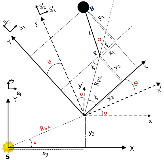
Fig. 2 Geometry used to determine the velocities of the asteroid and the balloon in the inertial coordinate system. The color figure can be viewed online.
The position and velocity vectors of the asteroid’s center of mass are represented by equations (1) and (2), and the position and velocity vectors of the balloon are shown in equations (3) and (4). The equations are described in the inertial coordinate system (centered in the Sun):
From equations (2) and (4), we have the following scalar products:
The total translational kinetic energy is composed of two parts, the first one associated with the PHA and the second one with the balloon, according to equation (7).
We assume that the asteroid rotates and the balloon is static with respect to the asteroid. The coordinate system defined on the asteroid originates from its center of mass and it is aligned with its main axes. In equation (8), we have the total rotational kinetic energy, given by:
where I A is the moment of inertia with respect to the axis normal to the plane of motion of a homogeneous body resulting from the association of the asteroid, the tether, and the balloon.
Bennu has an oblate spheroidal shape with a prominent equator, frequently called “top-shaped” (Michel et al. 2020). Simulations using the spherical harmonics expansion to consider the asteroid oblateness did not show significant differences when compared to a sphere for this type of configuration (Venditti et al. 2020). Therefore, Bennu was modeled as a sphere with a diameter of 492m in this paper.1 Equations 9 show the two formulations that are used to calculate I A with respect to the center of mass of the asteroid. The first one was used for the asteroid alone, while the second one is an approximation for the asteroid-tether-balloon system. These two formulations are necessary, since the simulations using the asteroid and the simulations using the asteroid-tether-balloon models are made independently of each other.
where R 0 is the characteristic length of the asteroid.
Therefore, by replacing equations (5) and (6) in equation (7) and summing the expression obtained with equation (8), we have that the total kinetic energy of the system is given by:
The acceleration due to the solar radiation pressure depends on the orientation
of the Sun light with respect to the surface of the balloon. However, we
consider a simplified model where the SRP is always normal to the surface of the
balloon (Farrés 2017). The effect of
imperfections and absorptions of photons by the surface of the balloon can be
considered in a more realistic model and requires a more detailed study (Deng et al. 2019), which is out of the
scope of this work. Thus, the acceleration due to the SRP
where c
r
is the solar radiation pressure coefficient (considered equal to 2 for
maximum reflectivity), P
rad
is the SRP at an au (4.56 × 10⁻⁶
N/m2), where au is the Astronomical Unit (the
average distance Sun-Earth, 1.49597870700×10⁸ km),
A
B
is the projected area in the direction of the Sun, m
B
is the mass of the balloon,
In this study, the phenomenon of occultation of the balloon by the asteroid (shadow) is not considered. The SRP acceleration on the asteroid is also neglected, and only the effects on the balloon are analyzed. Therefore, the absolute value of the solar radiation force can be expressed as (Luo et al. 2009):
where R SB is the distance between the Sun and the balloon.
According to McInnes (1999), we can interpret β as the ratio between the solar acceleration and the gravitational attraction acting on the balloon, i.e.,
Since the SRP is proportional to the inverse square of the distance to the Sun, it is common to write its effect as a correction of the Sun’s gravitational attraction (Simmons et al. 1985; McInnes 1999; Zotos 2015). Thus, the resulting force acting on the balloon, written as a function of the parameter β, is:
Based on Brouwer & Clemence (1961), we can write the potential energy between the Sun and the asteroid, and the Sun and the balloon, respectively, as:
The position of the balloon relative to the asteroid is kept fixed. We assume that there is no gravitational potential between these bodies. The distance between the Sun and the balloon (R SB ) is determined by applying the cosine law in the triangle (SAB) shown in Figure 1. We assume that the distance between the Sun and the asteroid is much greater than the distance between the balloon and the asteroid (R AB << R SA ). Then, we can develop 1/R SB in a power series as a function of R SA . Equation (17) shows the result of this series truncated in the second term.
The total gravitational energy of the system is given by the sum of equations (15) and (16), after replacing R SB by equation (17). The final result is shown in equation (18).
Thus, the Lagrangian of the system is obtained by subtracting the kinetic energy from the potential energy. The result is shown in equation (19).
Finally, the second-order differential equations for the generalized coordinates R SA , ν, θ for the asteroid-tether-balloon system are obtained from the Lagrange equations, assuming that the nonconservative forces are zero. The results are shown in equations (20), (21) and (22).
2.3. Main Parameters and Overview of the Simulations
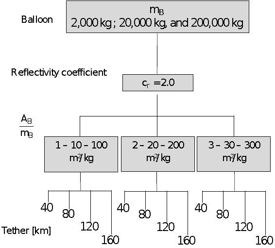
Recent papers found in the literature use high values of the area-to-mass ratio to study the dynamics of debris in Earth’s orbit (Valk & Lamâıtre 2008; Anselmo & Pardini 2010; Rosengren & Scheeres 2013; Früh & Moriba 2014). The membranes known as “gossamer” can be used to build large thin structures. These structures can be useful in many space applications (Deng et al. 2019). Another example of future missions that will use large structures is to transport telescopes to the stratosphere for scientific purposes.2 Inspired by these ideas, we use high values of area-to-mass ratio for a different purpose: to maneuver an asteroid. We propose to use a balloon that uses the SRP as a propulsion system and this concept is tested in this work. The effects of the balloon’s mass (m B ), the length of the tether (l), and the area-to-mass ratio (A B /m B ) of the spacecraft are the parameters considered in the analysis, as shown in the flowchart of Figure 3 .
We use two parameters δ and ∆ to measure the deviation of the asteroid due to the balloon. These two parameters are, respectively, the distance Earthasteroid, which is calculated for trajectories with and without the presence of the balloon; and the relative distance between the trajectories with and without the balloon. The latter can be calculated because the equation of motion of the asteroid, considering the balloon, is integrated along with the equation of motion of the asteroid without the balloon, respectively. Then, the trajectory of the asteroid without the balloon can be considered as a reference trajectory. Figure 4 shows the two main deviation parameters. These parameters are also used to assess the efficiency of using a balloon to deflect an asteroid, since the larger the deviation in the trajectory the more efficient is the configuration adopted. Both parameters are calculated using the distance between two points in the Cartesian plane.
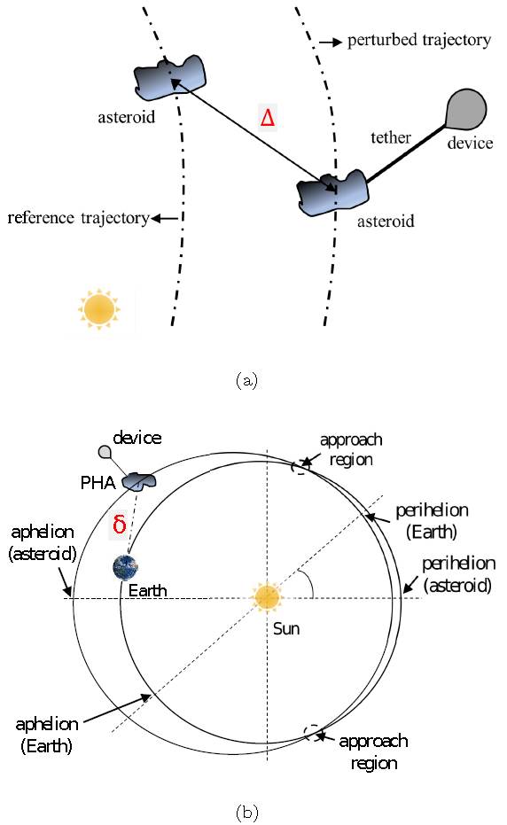
Fig. 4 Parameters of deviation between (a) the trajectories of the PHA with the balloon and without the balloon (b) asteroid-tether-balloon system and Earth. The color figure can be viewed online.
The effect of the SRP acting on the system is inserted in the mathematical model through the parameter β. The relation of A B /m B with β, for c r = 2.0, is given by [see equation (13)]:
3. RESULTS AND ANALYSIS
In this section, we analyze the results obtained from the numerical simulations using the proposed physical model. In § 3.1, the lowest fuel consumption for a transfer between Earth and Bennu is determined for a 20-year interval, from 2020-2040. The relative distance ∆ between the trajectories of the asteroid with the balloon and without the balloon (reference trajectory), and the distance δ, from the PHA to the Earth, are discussed in § 3.2 and § 3.3, respectively.
The root mean square (RMS) is frequently used to calculate experimental errors. However, this method can be used to compare two models, as in Sanchez et al. (2014). Therefore, we calculate the RMS deviation from the orbit with the balloon with respect to the orbit without the balloon. In this case, empirical equations are obtained to relate the tether length and the area-to-mass ratio with the mean deviations (§ 3.4).
3.1. Determination of the Initial Position of the Bodies
Numerical simulations were performed for asteroid 101955 Bennu. The main reasons for choosing this asteroid are: (i) it is one of the top PHAs on the Sentry list3, which monitors objects with the potential of a future impact with the Earth; (ii) it has low orbital inclination (our physical model is twodimensional); (iii) it is the target of the OSIRISREx mission. Table 1 shows the orbital parameters of this body, which are: semi-major axis (a), eccentricity (e), perihelion distance (q), inclination (i), longitude of the ascending node (Ω), argument of perigee (ω), and orbital period (P B ). In addition, Bennu has a mass of 7.8 × 10¹⁰ kg, with dimensions 0.565 km × 0.535 km × 0.508 km, and a rotation period of 4.297h.
TABLE 1 ORBITAL PARAMETERS OF 101955 BENNU AT EPOCH 2455562.5 (2011-JAN-01.0)
| Element | Value |
|---|---|
| a | 1.12639 au |
| e | 0.20374 |
| q | 0.89689 au |
| i | 6.03493◦ |
| Ω | 2.06087◦ |
| ω | 66.22307◦ |
| P B | 436.64873 days |
The choice of the initial date for the position of the bodies (Bennu and Earth) was obtained through a model based on the patched-conics (Crenshaw 1963; Miele & Wang 1999; Sanchez et al. 2019). The best trajectory is found such that it minimizes the fuel consumption (∆V ) required to transfer a spacecraft from the Earth (circular orbit with 200km altitude) to the desired body in an given time interval (2020-2040). The initial position of the bodies and the arrival and departure dates of the spacecraft are shown in Figure 5. The duration of the transfer is 353 days, and the consumption required by a bi-impulsive maneuver is ∆V TOT = 3.243km/s. Notice that the arrival date is very close to the crossing point of the orbits of Bennu and the Earth. This result is expected, because maneuvers for orbital inclination correction are very costly. It was also considered that the tether is fixed to the balloon immediately after the arrival of the spacecraft in Bennu (red trajectory).
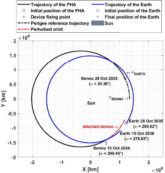
Fig. 5 Initial position of the bodies and the orbital geometry. The color figure can be viewed online.
Table 2 contains the argument of pericenter (ω) and the longitude of the ascending node (Ω) used to define the position of the Earth’s perigee (π E ) and Bennu’s perigee (π B ). From this, it was considered that the line of apsides of the orbit of Bennu coincides with the X-axis of the inertial system, which means that the perigee of its orbit is on that axis. The same hypothesis was used to numerically integrate the Earth’s orbit. However, for the launch date of the spacecraft (10.28.2035), the phase angle between the line of apsides of Bennu and the Earth is ψ = 34.69◦. In this way, it is necessary to rotate the Earth coordinates position using the coordinate transformation matrix between the inertial system and the rotational system, centered in the Sun (Vallado 1997).
TABLE 2 DEFINITION OF LINE OF APSIDES OF EARTH AND BENNU AT INITIAL TIME
| Date of departure of the spacecraft | Line of apsides | |||
|---|---|---|---|---|
| Earth | Bennu | |||
| ω(°) | Ω(°) | ω( ° ) | Ω(°) | |
| 28 Oct 2035 | 287.90 | 175.18 | 66.46 | 1.92 |
Finally, Table 3 presents the initial conditions for the simulations.
3.2. Determination of Distances from the Earth
In this section, we will discuss the orbit deviation’s of the PHA by the balloon connected with the tether, using masses of 2000kg, 20000kg, and 200000kg for the balloon. The simulations show that the use of the balloon results in two types of deflections. The first one will be called a negative deflection, i.e, Bennu is brought closer to Earth, as observed in Figure 6 at a time of 56.30 years. However, at a time of 122.99 years, the deflection is set to positive, because the use of balloon increases the distance between Bennu and the Earth.
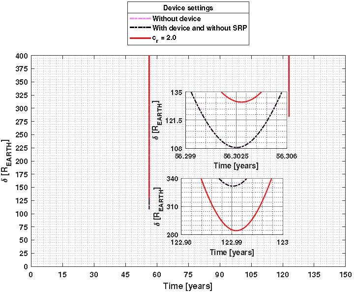
Fig. 6 Bennu-Earth distances for values smaller than 400 R EARTH , for the case of m B = 200000kg and A B /m B = 300 m2/kg. The color figure can be viewed online.
Figure 7 shows the distances from Bennu to Earth in separate graphs, for the two scenarios mentioned above; the cases in which the deviations of the trajectories without balloon (“dashed pink line curves”) and with the balloon, but without taking into account the SRP (“black dashed curves”). The two dashed curves are practically overlapping, since the mass of the balloon is very small compared to Bennu’s mass. Therefore, the center of mass of the system suffers a small displacement and, consequently, the deviations are less significant, in contrast with the results obtained by Venditti et al. (2020), since the ballast is much more massive than the balloon considered in this paper.
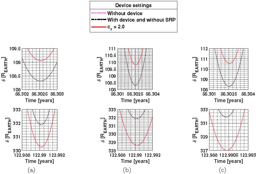
Fig. 7 Distance between PHA and the Earth in terrestrial radius units considering a balloon with m B = 20000kg for (a): A B /m B = 100 m2/kg, (b): A B /m B = 200 m2/kg, and (c): A B /m B = 300 m2/kg. The color figure can be viewed online.
For balloons with mass of 2000kg and 200000kg, the same results shown in Figure 7 were obtained. However, they were omitted here. Equation 24 allows us to directly evaluate the deviations between the black dashed curve (without balloon) and the red curves (with balloon),
where δ NP and δ P refer to the distance between the PHA and the Earth, with and without the attached balloon, respectively.
In Figures 8(a) and 8(c), the deflections were positive, that is, in these cases the use of the balloon decreased the distance between the Earth and the PHA. In contrast, Figures 8(b) and 8(d) show that the deviations are negative, meaning that the PHA’s trajectory is increasing its distance from the Earth. In both cases the ratio A B /m B amplifies the magnitude of the deviations. For example, in 56.3 years it is possible to deflect the asteroid by 25R EARTH , considering a balloon of 200000kg and, A B /m B = 300 m2/kg.
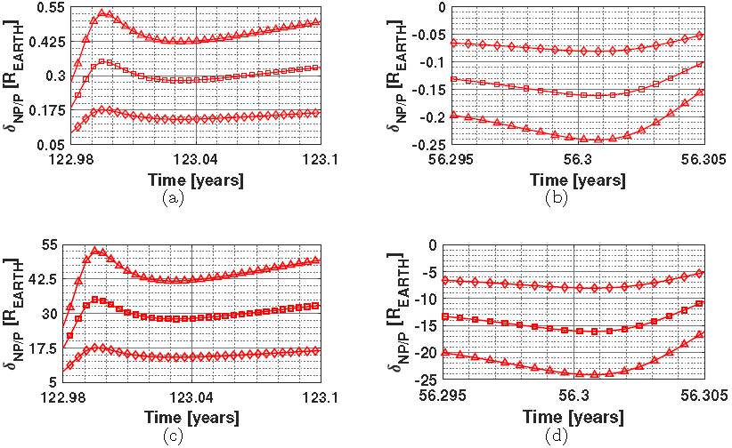
Fig. 8 Difference in δ considering a balloon with 2.000kg, (a) positive deflection, (b) negative deflection; and a balloon with 200000kg, (c) positive deflection, and (d) negative deflection. The lines with diamond markings refer to A B /m B = 100 m2/kg, square markings to A B /m B = 200 m2/kg, and triangle markings to A B /m B = 300 m2/kg. The color figure can be viewed online.
3.3. Deviations Due to Orbit Perturbation
The simulations were made with the four tether lengths presented in Figure 3. However, in this section, only the results for the 40km tether are shown. The effect of the tether length on the deviation is a subject of analysis in § 3.4.
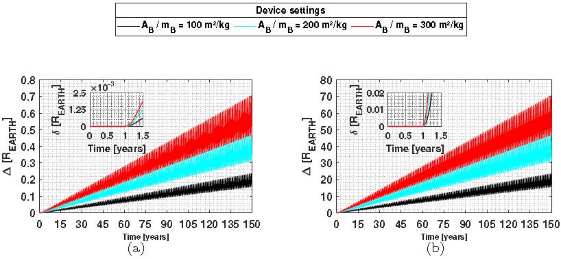
The analysis shown in Figure 9 was made for 150 years and it shows the deviations in the trajectory due to the balloon [see Figure 4(a) ], considering a balloon with 20000kg. The deviations are proportional to A B /m B . Simulations for longer periods of time, and perturbations, such as N-bodies, general relativity, Yarkovsky effect, flattening of planets and moons, among others, should be considered in the physical model, but this is not the main objective of the present paper. Furthermore, the method proposed in this work may be more appropriate when considering warning times of a few decades, as is the case with the gravity tractor method (NTRS 2015).
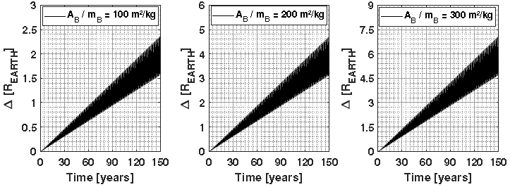
Fig. 9 Deviation between the trajectories of the PHA with and without balloon in terrestrial radius units, considering a 20000kg balloon and l = 40 km.
The results for balloons with masses of 2000kg and 200000kg are shown in Figure 10. In the first year of simulation there is no deviation, because this period refers to the time that the spacecraft travels to Bennu, as can be seen in the magnification of this part of the figure. The magnitude of the deviations when increasing the mass by a factor of 100 is also shown. For example, a less massive balloon generates a deviation of 0.70 R EARTH when A B /m B is 300 m2/kg [see Figure 10(a) ], whereas a more massive balloon (one hundred times larger) enables deviations of approximately 70 R EARTH for the same settings [see Figure 10(b) ].
3.4. Effects of the Tether Length: Mean Deviation of the Trajectory
To summarize the large amount of results and to present them in a clear way, we use the root-meansquare deviation, according to equation 25. Usually, the RMS method is used to calculate the error of an experimental measurement with respect to a reference value, or even to calculate the error of an approximation with respect to a true value of this function (Freedman et al. 2007; Sanchez et al. 2014).
However, this method can also be used to compare two sets of values, one used as a reference set and the other one as the “measurement” set. In our case, we used the RMS to compare the trajectory without balloon, which is our reference orbit, with the trajectory generated by the simulation considering the balloon. In this case, this RMS deviation shows the deviation from one trajectory to another. Hence, we need to determine the differences between the reference and perturbed (with balloon) orbits. Particularly in this problem, we define the reference values (y k ) as determined by the Keplerian orbit, and the perturbed values (ŷ k ) as those obtained by the perturbed system, with the addition of the tether and the balloon. The total number of points evaluated corresponds to the value of N.
The RMS deviation for a balloon with a mass of 20000kg is shown in Figure 11. We used the RMS deviation to quantify the effect of the tether length (l) on deviations with the Earth (δ). Using this technique, it is possible to note that the change in RMS δ is less sensitive to l, considering the values of m B used. In all cases, we have determined linear equations that relate these two parameters. The residuals between the values calculated with the model and the linear approximation were less than 0.1 km, as seen in Figure 12(a). Figure 12(b) shows the norm of residuals, when is a measurement of the quality of the fit, where a smaller value indicates a better fit.
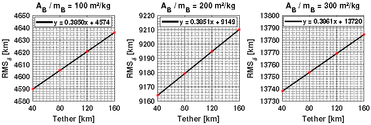
Fig. 11 RMS deviations for δ considering a balloon with a mass of 20000kg. The color figure can be viewed online.
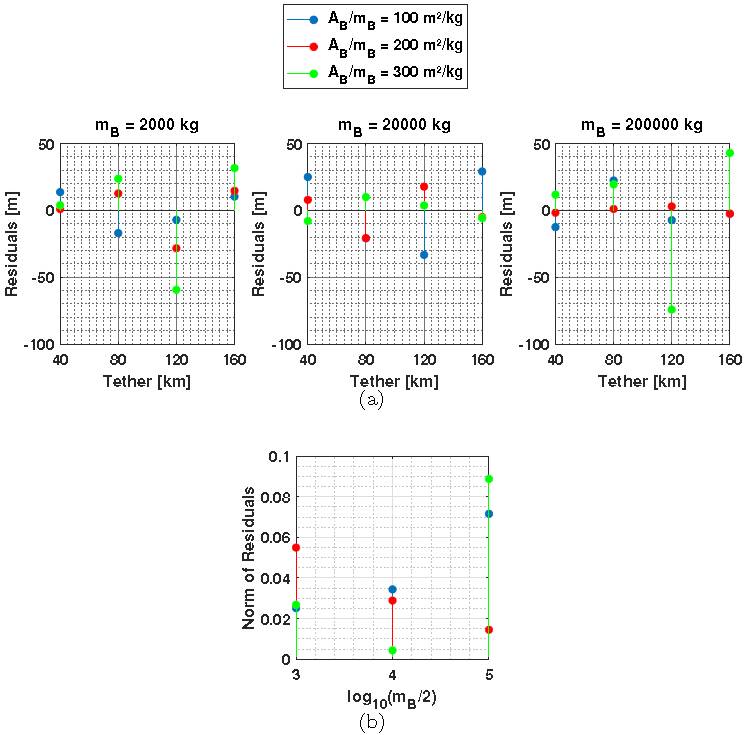
Fig. 12 Comparison between the calculated data and the linear fit for m B = 2000kg, m B = 20000kg, and m B = 200000kg; (a) residuals, (b) norm of residuals. The color figure can be viewed online.
Table 4 shows the differences with respect to the longest and shortest tether length considered. It can be seen that A B /m B has little relevance for each particular analysis of m B , but the magnitudes of the deviations increase by the same factor (10) as the increase in m B .
TABLE 4 EFFECT OF TETHER LENGTH (l) IN RMS δ CONSIDERING THREE MASS VALUES (M B ) FOR THE BALLOON
| AB/mB [m2/kg] | RMSδ160km − RMSδ40km [km] | ||
|---|---|---|---|
| m B = 2000kg | m B = 20000kg | m B = 200000kg | |
| 100 | 4.658 | 46.268 | 462.625 |
| 200 | 4.638 | 46.249 | 462.435 |
| 300 | 4.625 | 46.248 | 462.284 |
Figure 11 shows the three curves (with their respective equations) obtained by the linear fit. This same procedure was performed for the other two values of m B used, but the graphs are omitted. The linear coefficient of these equations can be divided by A B /m B , such that three linear equations for RMS δ , as a function of l and A B /m B , are obtained. Then, a single general equation was obtained for the calculation of RMS δ as a function of all the balloon parameters (l, A B /m B , and m B ), as given in equation (26). The RMS δ has a linear behavior that is directly proportional to 10−5 m B . The new coefficients obtained in each step, for the reduction of the equations, were calculated using a simple mean.
In this empirical equation, it is verified that, for the same value of A B /m B , increasing the mass of the balloon (m B ) implies that we must increase the cross section area illuminated by the Sun (A B ), that is, the balloon will have larger physical dimensions.
3.5. A Particular Case: Deflection of Small Asteroids
In this section, we will test the concept of transferring a small asteroid, similar to the one in the Chelyabinsk event in 2013, to orbits closer to the Earth, for scientific and space mining purposes. The deviation method we propose provides trajectory approximations in shorter times (18.9 years), because the mass of the asteroid is of the order of 106 kg. Moreover, we will also show the case where the asteroid can be deflected farther from the Earth after 56.3 years from the start of the application of the method. The initial condition vector of the asteroid considered is shown in Table 3 (§ 3.1), as well as the other parameters.
Figure 13 shows the effects of m B and A B /m B for the situation where the asteroid would be approaching the Earth. In the cases discussed in the previous sections, we had m B /m A = 2.56 × 10⁻⁸ for m B = 2000kg. However, here we consider m B /m A = 2.56 × 10⁻⁴. The reduction of this ratio implies that a mass of 2000 kg becomes more effective in changing the trajectory of the asteroid, as expected. This effect causes a deviation of about 0.8 R EARTH in approximately 19 years of simulation and is determined when the magenta and black curves are compared. The lengths of l considered here do not change this deviation beyond about a few hundred kilometers, because the operating time is short and m B is small. In this way, the center of mass of the system undergoes very small displacements.
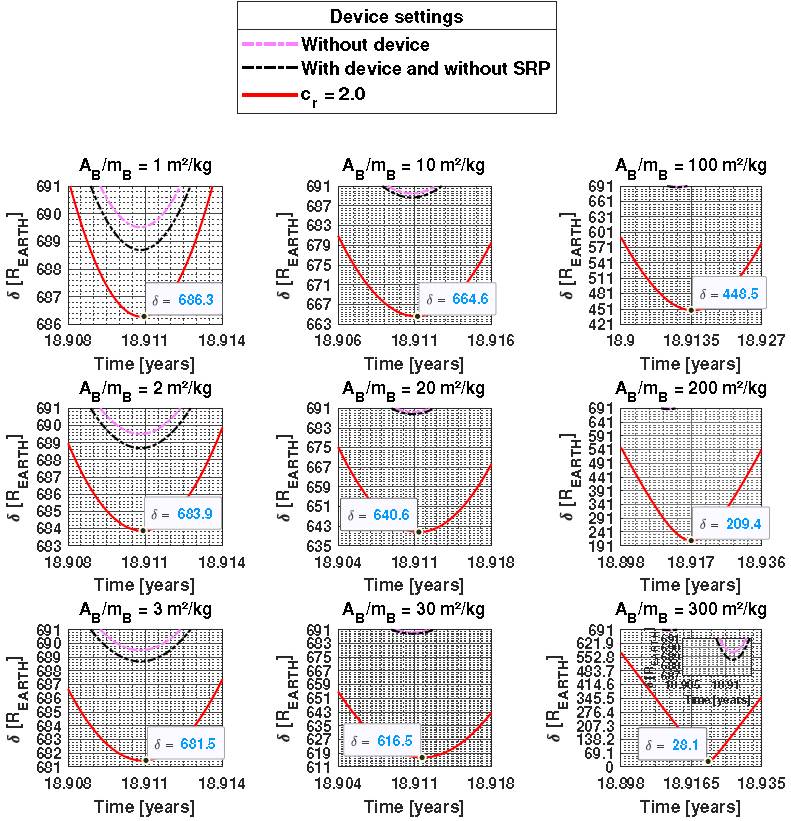
Fig. 13 Distance between a small asteroid and the Earth, in terrestrial radius units, considering a balloon with m B = 2000kg and a tether of 40km, for a period of operation of less than 20 years. The color figure can be viewed online.
We were able to transfer an approaching asteroid from a distance of 689.5 R EARTH to approximately 28 R EARTH , using A B /m B = 300m2 /kg. This would bring it closer to Earth by 180000km.
Table 5 shows the effects of the balloon parameters on the variation of δ. Note that deviations of more than 200 R EARTH were obtained by using the proposed technique to bring the asteroid closer to the Earth. This shift saves very large amounts of fuel, if these transfers are performed using engines.
TABLE 5 APPROXIMATE VALUES OF δ DUE TO THE CHANGES OF A B /M B *
|
|
|
|---|---|
| 1 - 2 - 3 | 2.34 |
| 10 - 20 - 30 | 23.40 |
| 100 - 200 - 300 | 234.00 |
* For the case of deflection of the trajectory of the asteroid to bring it close to Earth.
Figure 14 shows the results for the case where the PHA trajectory is increasing its distance from the Earth. The asteroid approaches 108 R EARTH in natural conditions (black curves) after 56.3 years of simulations. The increase in l at 40km corresponds to an approximate increase of 2.5 R EARTH in the deviation δ, for any A B /m B configuration.
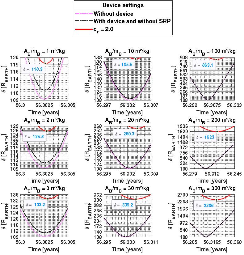
Fig. 14 Distance between a small asteroid and the Earth, in terrestrial radius units, considering a balloon with m B = 2000kg and a tether of 40km, for a period of operation of less than 60 years. The color figure can be viewed online.
Table 6 shows the approximate values for the variations caused in δ due to changes in the balloon parameters. The deflection is increased by 7.25 R EARTH as A B /m B increases by 1m2 /kg. For example, a balloon with 3m2 /kg of mass area offers an additional 14.5 R EARTH in δ, when compared to a balloon with 1m2 /kg. This would be the simplest design and construction out of all the balloon configurations considered, but it is important to see the possibilities of this technique. Deviations of more than 700 R EARTH can be achieved. Of course they depend on high values of the area-to-mass ratio, but our goal is to show the potential of the technique, even if there are technological problems for its applications. Besides, there are also intermediate values that are closer to be technologically viable.
TABLE 6 APPROXIMATE VALUES OF δ DUE TO THE CHANGE OF A B /M B *
|
|
|
|---|---|
| 1 - 2 - 3 | 7.25 |
| 10 - 20 - 30 | 72.50 |
| 100 - 200 - 300 | 725.00 |
*For the case of deflection of the trajectory away from Earth.
Equation (27) provides approximate values of ∆ as a function of the balloon parameters for 50 years of operation. The effect of l is much smaller than the effect of A B /m B .
Table 7 shows the variations in ∆ due to changes in the balloon parameters. ∆ is little sensitive to l and is directly proportional to A B /m B . There is also a large range of values, of the deviations, from
6.7 REARTH to near 670 REARTH.
4. CONCLUSION
In this work, the main objective was the investigation of an alternative solution to modify the orbit of an asteroid that poses a risk of collision with Earth, or to bring the asteroid closer for mining purposes or scientific research. The proposed technique suggests the use of one balloon (or several) with a large area-to-mass ratio that is attached to the asteroid with a tether, using the SRP to alter the trajectory of the asteroid. This technique enables the deviation of the whole asteroid, avoiding unpredictable situations caused by fragmentation, as might happen when using other deflection methods, such as the kinetic impact or nuclear explosives.
There are two factors that modify the trajectory of the asteroid. The force coming from the SRP, and the displacement of the center of mass of the system due to the mass of the balloon. The deviations coming from the SRP are much larger and dominate the scenario, because the mass of the balloon is much smaller than the mass of the asteroid. Although it is a technique that takes several years to deliver results, larger deviations can be obtained depending on the configuration of the balloon, when compared to the use of the gravity tractor, which is a technique that also requires a large period of time to be implemented.
In the case that we consider, an asteroid with mass similar to that of (21088) Chelyabinsk, the minimum distance Earth-asteroid was reduced by 1.2%, 10.6% and 96%, when A B /m B was 3m2 /kg, 30m2 /kg and 300m2 /kg, respectively. This result was obtained in less than 20 years of operation. In addition, the distance from the asteroid after 56.3 years of operation was 22 times greater when we consider A B /m B = 300m2 /kg.
On the other side, if the goal is to bring the asteroid closer to Earth for mining or scientific research, a decrease in distance of the order of 700 R EARTH was achieved. Those are important values, because a space mission would require much less fuel to reach the asteroid.
It is noted that the largest deviations are obtained using large values of area-to-mass ratio, which would cause technological problems for the construction of the balloon, but the goal of the present paper is to show the potential of the proposed technique, not taking into account technological problems. Besides, there are also intermediate values of deviations that do not require such large balloons, specially considering the possibility of using several smaller balloons.
Therefore, shorter tethers can be used to attach multiple balloons to the surface of the asteroid, thus constituting large areas for collecting the SRP. This configuration is much more feasible, because it reduces the structural stress in the tether, facilitating the construction of the whole apparatus, which would be fixed on the asteroid. In addition, other cases could be predicted from the empirical equations that relate the main parameters of the model.

