


 nueva página del texto (beta)
 Inglés (pdf)
 Artículo en XML
 Referencias del artículo
 Enviar artículo por email
 Citado por SciELO
  Similares en
SciELO
Similares en
SciELO 
 Permalink
1. INTRODUCTION
Following the experience gained in the development of the CAMILA near-infrared (NIR) camera (Cruz-González et al. 1994) for the 2.1m telescope of the San Pedro National Observatory operated by UNAM, México, we decided to design an improved NIR camera for the 2.12m telescope of the Guillermo Haro Astrophysical Observatory (OAGH) (see Figure 1) in Cananea, Sonora, México owned by the Instituto Nacional de Astrofísica, Optica y Electrónica (INAOE). This NIR camera is called the Cananea near-infrared camera (CANICA). In the year 2000 the project received a grant from the Mexican science funding agency CONACyT for the development of this instrument. CANICA saw its first light in the 2nd quarter of 2002. In the year 2012, a new instrument called POLICAN (Devaraj et al. 2015, 2017b) was attached to CANICA to carry out linear polarimetric studies.
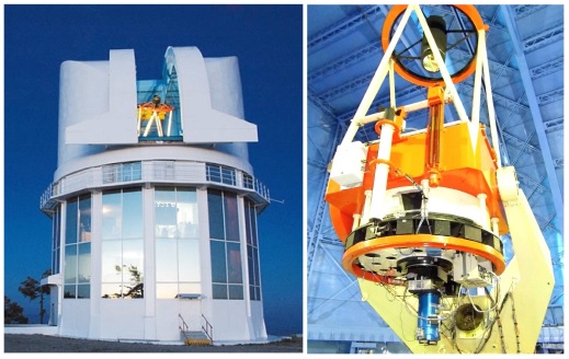
Fig. 1 The left image shows the main building of the Guillermo Haro Astrophysical Observatory (OAGH) in Cananea, Sonora, México. The 2.12m telescope is shown on the right image with CANICA attached as the backend instrument. The telescope is a Ritchey-Chrétien design with an equatorial fork mount.
CANICA was conceived to perform as a general purpose NIR instrument that could be used both on dark and bright nights. The NIR spectral region is best suited for carrying out galactic studies of the interstellar medium around stars, nebulae, supernovae, stellar winds and for planetary systems search (e.g. Carpenter et al. 2001; Sugitani et al. 2002; Williams et al. 2009). These studies help to understand fundamental questions regarding star and planet formation, whereas extragalactic studies in the NIR of sources such as AGNs provide important information on thermal (accretion-discs) and non-thermal (synchrotron) emission in these objects. These data allow us to characterize their variability and help to study the physical processes that dominate the flaring and emission from AGNs (e.g. Bonning et al. 2012; Patiño-Alvarez et al. 2017). The study of´ galaxy morphology is well complemented in the NIR because the dust extinction is largely removed and the stellar emission dominates the H band.
CANICA is similar to several cameras that operate at NIR wavelengths such as the CFHTIR camera (Starr et al. 2000), NOTcam (Abbott et al. 2000), NICS camera for TNG (Baffa et al. 2001), SIRIUS (Nakajima et al. 2002), NIRI (Hodapp et al. 2003). CANICA is based on the Rockwell HAWAII focal plane array with a HgCdTe detector capable of efficiently detecting light from 0.85 to 2.40µm. The entire camera is contained in a cryostat with a simple optical design consisting of cooled refractive optics. During the design phase various detector materials were considered. Finally, HgCdTe arrays were preferred rather than InSb and InGaAs arrays, as they were large format detectors with high quantum efficiency, low dark current and ease of maintainance at low temperatures.
In the following sections we describe the mechanical design, optical design, detector array, camera electronics, software control and some observational results of CANICA.
2. MECHANICAL DESIGN AND CRYOSTAT
The 2.12m telescope at the OAGH observatory has a Ritchey-Chrétien optical configuration. Hence, the system consists of a hyperbolic primary mirror of 2.12m diameter and a secondary hyperbolic mirror of an aperture of 50cm, for a focal length of 25.44m. The camera CANICA has a compact design in order to operate at the focal plane of the telescope.
CANICA is made up of a cryostat enclosed by a large aluminum dewar custom-designed and built by Infrared Laboratories (IR Labs). The shape of the entire unit is a cylindrical tank with length of 61.6cm and diameter of 31.9cm. The cryostat is thermally insulated by a vacuum chamber at the outermost layer. The inner vacuum wall of the vacuum chamber is a cold shell surrounded by a radiation shield which covers the components inside the cryostat. A charcoal getter is located inside the vacuum chamber in order to adsorb the remaining gases and maintain a high vacuum. The camera is cooled by liquid nitrogen with an operating temperature between 77K and 80K. An entrance port at the bottom, serves for re-filling the liquid nitrogen. A vessel with a capacity of 8.5litres for storing liquid nitrogen is positioned behind the cold plate where the detector array is positioned at the lower part of the cryostat. In operation, the holding time of liquid nitrogen is 8hours. In Figure 2 we show the schematic design of CANICA in side view, with its mechanical and optical components highlighted.
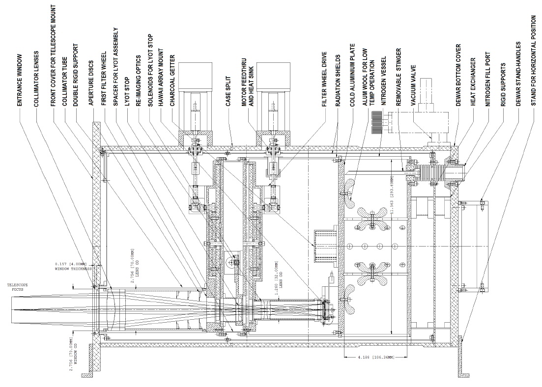
Fig. 2 The figure shows the IR Labs mechanical design of the CANICA instrument in side view, with all the important components highlighted. The CANICA optics are housed inside the cryostat, which is cooled with liquid nitrogen to 77K. A vessel for storing liquid nitrogen is positioned behind the detector array unit. The side view image shows the light path passing through all the components inside the camera.
The front end of CANICA has a high transmittance, optically flat, entrance window of 70.0mm diameter. In order to accommodate the filter wheels, the entire optical train is positioned off-center in the cryostat. This leads to connecting CANICA to the telescope using an adapter to compensate the eccentricity in the light path. The optical components of CANICA follow three sections inside the cryostat. The input light beam passes through the collimator tube, the filter wheels located near the exit pupil plane and a camera, focusing on the detector array.
3. OPTICAL DESIGN
CANICA is an instrument envisioned to be a multi-function NIR multi object spectrograph as well as a direct camera. Budgetary restrictions lead us to a downgraded version: a simple 2:1 cooled image reducer. The instrument’s functionality is fulfilled by having an area of a collimated beam, filter wheel sets, and a system of reimaging optics on the detector array. These requirements were realized by a good optical design with a modest number of optical components. The optical design ensures that all the components are installed with their positions well constrained within the size of the cryostat. The optics were fabricated by Janos Technology Inc. All lenses are made of ZnS material with strict specifications on their radius and thickness. The lens setup in the collimator and the focusing system consists of un-cemented triplet lenses. The thermal emission from the components in the optical setup is highly reduced as the cryostat is cooled to 77K. Extra radiation and reflected light from telescope, dome and structures is minimized by having set of cooled baffles in the light path.
In the following sections the details and characteristics of these systems are described.
3.1. Collimator
The input beam from the telescope passes through an un-cemented ZnS triplet, which produces an achromatic collimated paraxial beam at the exit pupil. The collimator design was optimized using ZEMAX software. The ray tracing of the optical components is shown in Figure 3.
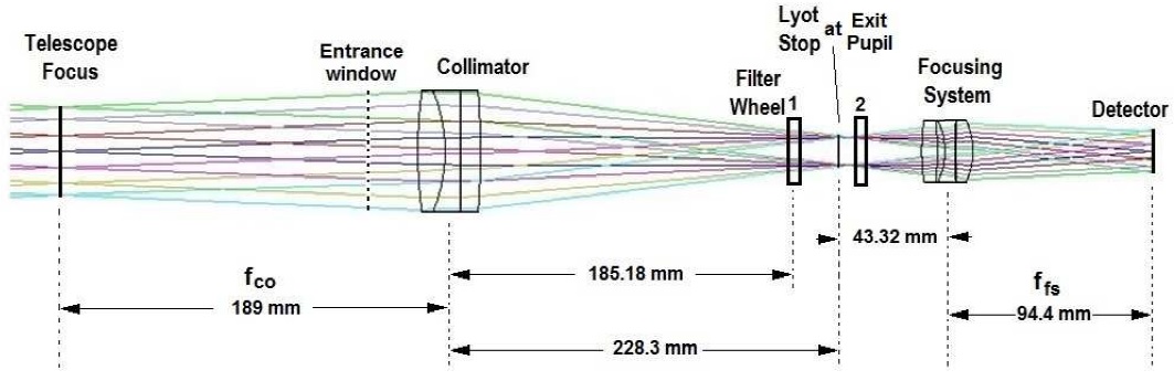
Fig. 3 Ray tracing diagram of the optical setup in CANICA. The camera optics of the collimating and focusing systems consist of un-cemented ZnS triplet lens setups, distances between each optical components are marked with the focal length of collimator and focusing system. The total distance from the entrance window to the detector in the cryostat is about 38cm.
For a collimator of focal length fco of 189mm, a collimated pupil diameter Dco of 15.75mm is obtained. This setup yields a distance of 228.3mm between the collimator and the exit pupil, thus providing adequate space for placing baffles, filters and a Lyot stop. This distance also provides room to place in the future additional optics such as grisms for multi-functioning of CANICA.
3.2. Filter Wheels
The CANICA filter wheel assembly consists of two filter wheels each one capable of containing 13 filters, plus a dark slide and a clear window. Some filters were procured as a part of large consortium purchase for the standardization of infrared filter sets in the year 2000. The filter band pass and specifications are derived from the Mauna Kea Observatories NIR filter wheel set (Tokunaga et al. 2002). The CANICA optical setup was designed to allow to mount the filter wheels close to the the exit pupil, in order to reduce the size of the filters. The filters in the assembly are square-shaped with a dimension of 34.0mm. The primary broad-band filters are J(1.24µm), H(1.63µm) and K (2.12µm). Other narrow-band filters, which represent various spectral lines in the NIR, occupy the remaining positions in the filter wheel assembly. Two filter positions are completely covered for dark frame acquisition. A few additional vacant positions are available for new filters. In order to lower their thermal emission, the filters are cooled at the operating temperature of 77K. These wheels are controlled by an electronic drive with independent operation. Each filter wheel is driven by an off-axis stepper motor. Table 1 illustrates the CANICA filter wheels configuration.
Table 1 CANICA filter wheel configuration at 77k
| Filter Wheel 1 | Filter Wheel 2 | |||
| Position | Filter name | λc/Δλ | Filter name | λc/Δλ |
| 1 | Dark | Dark | J | 1.246/0.163 |
| 2 | H2,2-1 | 2.248/0.036 | H | 1.633/0.296 |
| 3 | H2,1-0 z | 2.178/0.025 | K′ | 2.119/0.351 |
| 4 | Pa β z | 1.316/0.020 | H-cont | 1.572/0.020 |
| 5 | Pa β | 1.283/0.021 | Feii | 1.641/0.030 |
| 6 | Empty | Empty | Feii z | 1.688/0.017 |
| 7 | Y | 1.026/0.049 | Hei-B | 2.059/0.030 |
| 8 | Hei-A | 1.077/0.019 | Hei-C | 2.189/0.032 |
| 9 | Pa γ | 1.096/0.017 | K-cont | 2.269/0.030 |
| 10 | Empty | Empty | Br γ | 2.168/0.030 |
| 11 | Empty | Empty | Br γ z | 2.224/0.024 |
| 12 | H2,1-0 | 2.107/0.033 | J-cont | 1.198/0.009 |
| 13 | Empty | Empty | CO,2-0 | 2.294/0.034 |
| 14 | HK notch | HK notch | H2,2-1 z | 2.308/0.025 |
| 15 | Empty | Empty | Empty | Empty |
3.3. Reimaging Optics
The reimaging system receives the collimated beam and focuses it on the detector. It is composed of a un-cemented ZnS triplet lens. For optimal operation at thermally affected wavelengths, a remotely removable Lyot stop is located at the exit pupil. The optics are housed in an aluminum tube passing from the filter wheels to the detector array. The lenses have an outer diameter of 32.0mm and allow light to pass without vignetting. All optical components are made of ZnS with anti-reflection coating.
The plate scale of the 2.12m OAGH telescope is 8.107arcsec/mm implying that an image of 1arcsec occupies a space of 123.35µm at the focus. CANICA, being a focal reducer of 2:1, provides a 5.5 × 5.5arcmin2 field-of-view (FOV) on the HAWAII detector array with a pixel size of 18.5µm, yielding a plate scale of 0.32arcsec/pixel. This plate scale is adequate to achieve Nyquist sampling under the best seeing conditions at the site.
3.4. Light Analysis
The optical components in CANICA were evaluated by light analysis using design software. In Figure 4 we show the spot diagram of a point source at 6 positions on the field. The black circle in the figure indicates the size of the Airy disc for a diffraction limited system (in this case the Airy disc is 25.62µm). The figure shows that the spots corresponding to all 6 positions on the field are smaller than, or equal to, the Airy disc, indicating a good balance of aberrations. Thus, the camera is a good optical system and meets the image quality requirements.
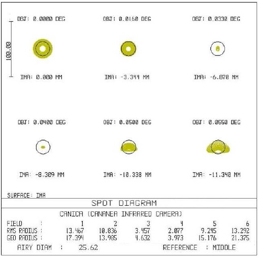
Fig. 4 Spot diagram evaluation of the CANICA optical system. The Airy disc for an ideal optical system in a diffraction limited case at λ = 1.75µm is shown as a black circle of diameter 25.62µm. The diagram represents point sources at 6 positions on the field at various distances from the paraxial focal plane.
4. DETECTOR ARRAY
CANICA hosts a first generation Rockwell Science Center HAWAII (HgCdTe Astronomical Wide Area Infrared Imaging) focal plane array (Hodapp et al. 1996) with 1024 × 1024 pixels. The HAWAII array is mounted in the cryostat on a fanout board and it is positioned on a thermally controlled stage. The fanout board consists of all the electrical connections to the array and is wired through a flexible circuit connecting to the pre-amplifier electronics. The preamplifier is located outside the cryostat and is connected to the SDSU controller(see § 5.1) for camera operation. The detector array consists of four independent quadrants of pixels having separate readout electronics. The quadrants are structured to have simultaneous readouts to obtain four outputs. Basic operation is carried out by six CMOS-level clocks, two 5V power supplies (one analog and one digital) and two DC bias voltages (one fixed and one variable). The readout is addressed by the clocks in the two shift registers (one horizontal and one vertical). To obtain a raster scan output, the horizontal register is clocked in the slow direction, with the vertical register clocked in the fast direction. The HAWAII readout is carried out by using reset-read-read mode, or correlated double sampling. Readout of the array consists of application of clock signals in which the array is reset, read, allowed to integrate, and reread, with the difference between the first and second reads being recorded, resulting in a correlated double sampled (CDS) image. With the CANICA readout structure, the first read is called the BIAS image and the second read is called the RAW image, with the CDS image being the difference of RAW and BIAS. The DC bias voltages for CANICA are kept between 3.3−3.8V and they determine the bias level of the images. The detector readout time for each read sample is 0.5s, so that the total readout time for a CDS image is 1s. The image delivery and storage time is 7s with the current electronic acquisition system. After image acquisition the BIAS and CDS images are delivered to the observer. The main characteristics of the CANICA camera are summarized in Table 2. Details of characterization and performance of CANICA are presented in Devaraj et al. (2017a).
Table 2 CANICA characteristics
| Quantity | Value | Unit | Description |
| Detector material | HgCdTe | HAWAII array | |
| Detector format | 1024 × 1024 | pixels | 4 Quadrants |
| Spectral Range | 0.85−2.40 | µm | 85% and above transmission |
| Pixel size | 18.5 | µm | Square pixels |
| Full well capacity | 100,000 | e− | Lab value |
| Plate scale | 0.32 | arcsec/pixel | on the detector |
| Total field of view | 5.5 × 5.5 | arcmin2 | Unvignetted FOV 4 × 4 |
| Operating temperature | 77−80 | K | Liquid nitrogen cooled |
| Minimum integration time | 1 | sec | In staring mode |
| Maximum integration time | 1 | hour | Used only for narrow-bands |
| CDS Readout time | 1 | sec | Sum of 1st and 2nd read times |
5. ELECTRONICS AND SOFTWARE CONTROL
CANICA was integrated and tested at the astronomical instrumentation laboratory of INAOE. Since the camera is equipped with a science grade infrared detector array, a low noise readout electronics was selected to operate the whole instrument. A graphical user interface was designed and developed (using open source tools) to simultaneously control the telescope positioning and the operations of the camera. In the following sections we present a functional description of the electronic systems and the architecture of the control software.
5.1. Readout Electronics
CANICA is driven by a second generation San Diego State University (SDSU) CCD controller (Leach et al. 2000). The SDSU controller consists of several electronic boards, namely: utility board, timing board, clock driver board, video processing board, and power control board. All the electronics of the controller are placed and protected inside a metallic housing connected to a power supply. The data acquisition cycle of the system begins at the host computer that is in charge of sending the user commands and of receiving the images captured by the HAWAII array. A PCI board is installed in the host computer, which operates at 250Mbit/s in transmission/reception mode using a 32-bit bus, and serves as the primary communication port. The host computer communicates directly to the timing board of the SDSU controller via a fiber optic link which is coupled to a SCSI-3 to fiber optic converter to convert the PCI signals into optical signals and vice versa.
The timing board is the core of the controller, since it is responsible for system initialization and waveforms generation. When a readout is requested by the user, the timing board communicates with the clock driver board and the video processor board through a VME backplane bus activating the clock driver board to provide the correct clock signals to operate the HAWAII array. At the same time, the video processor board is configured to generate the bias voltages for the array and to handle the data read from the array, in order to send the information to the host computer when a readout is completed. The preamplifier circuit for each detector quadrant is attached to the CANICA cryostat to better condition the HAWAII readout signals before they arrive at the video processor board (see Figure 5). Once the data are in the video board, all the quadrants are processed in parallel using separate A/D converters. At this point, the timing board gathers the image from each quadrant and transmits it to the host computer through the fiber optic link. The utility board is used to endow extra functionalities to the camera, like temperature monitoring inside the dewar, reporting the status of the controller power supplies, setting the exposure time, providing general purpose I/O communication, etc. The utility board is handled by the timing board in the same way as the video processor board and clock driver board.
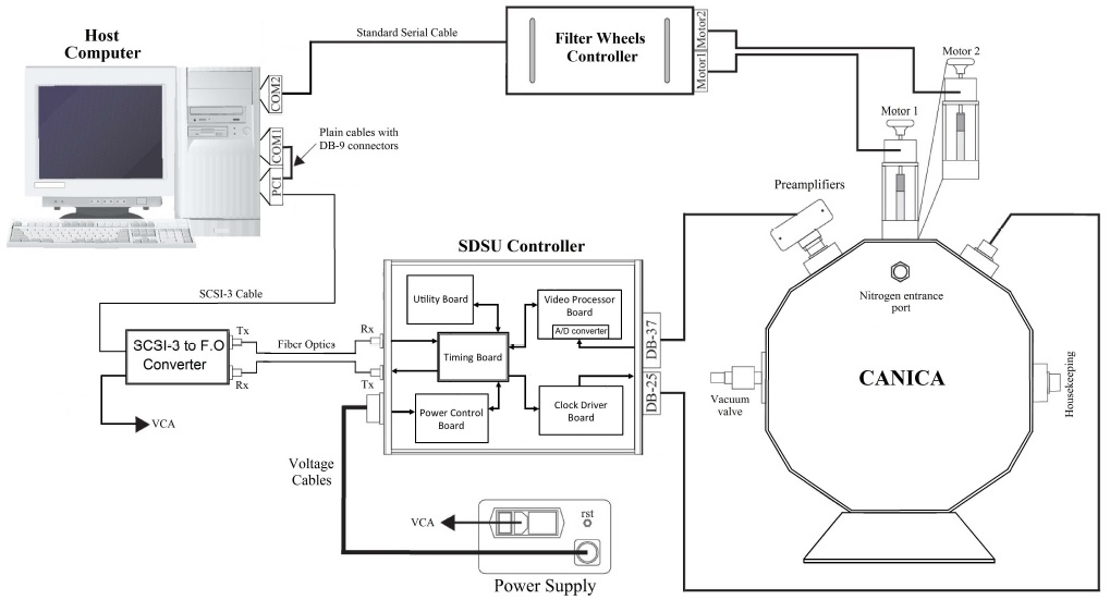
Fig. 5 Physical inter-connections from host computer to CANICA with all the different control units. The filter wheel controller and the SDSU controller are placed outside the dewar in a separate housing ttached to the telescope. The communication signals pass from the host computer through the PCI card and then via optical fibers to the SDSU controller, which then send clock signals for CANICA operation.
The power supply connected to the SDSU controller generates the main voltages, but they are not applied directly to the controller boards. Instead, the power control board is in charge of turning on/off the analog voltages to the rest of the boards in a programmable and controlled way to protect the electronics from over voltages, and in particular, to avoid damaging the HAWAII array.
A dedicated electronic unit is reserved for controlling the filter wheels via the RS-232 interface. This unit is not integrated to SDSU controller, but it is operated simultaneously by the user from the software interface in the host computer. Figure 5 shows the schematic connection of all the control units to CANICA.
5.2. Control Software
A control software with a graphical user interface (GUI) was developed to work under the Linux platform using open source technologies. The GUI provides access to configure all the functionalities of the CANICA such as: filter wheel positions, detector bias voltage, exposure time, co-adding, obtaining dark images, etc. Through this GUI, the user can control CANICA and operate the telescope simultaneously. This provides very flexible observation capabilities, since the system can be run in manual mode or in automatic mode. The manual mode of operation is used to initialize the whole system by setting up the desired configuration values to the instruments. This mode is useful when performing maintenance of CANICA. The automatic mode is used during observations, when the user can define an observing sequence using the scheduler implemented in the GUI. Once the user has defined the sequence, the scheduler dictates CANICA to automatically acquire images at all selected positions.
This allows the user to easily implement very complex observation programs.
The control software is technically divided into a low level and a high level software. The low level code, controlling the hardware, is written in C/C++, while the high level, software corresponding to the GUI, is written in Java. The C/C++ code and the Java code are linked together using the Java Native Interface (JNI).
The architecture of the control software is based on a shared memory scheme to enable data interchange between the telescope, CANICA, and the host computer. As shown in Figure 6, the host computer communicates with the observing tool in a bi-directional way, in order to allow the user to set the observation sequence in the scheduler. A state machine is responsible for the correct execution of the scheduled observations, pointing the telescope to selected targets and capturing an image with CANICA. Since all the information passes through the shared memory, the images coming from CANICA are sent to the host computer together with the telescope data via the monitoring tool. From here, the GUI is able to store the images in FITS format with the header information needed for post-processing.
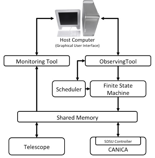
Fig. 6 Block diagram of the control software architecture for CANICA. The graphical user interface running in the host computer helps the user to send various commands to CANICA and the telescope through a shared memory scheme. Control and data inter-change take place with the help of observing and monitoring tools.
6. OBSERVATIONS
After successful first light, CANICA has been used for a variety of astrophysical observational projects. Earlier projects were concentrated on extragalactic studies. The M82 galaxy was studied in the J, H and K broad bands. These NIR data helped to the discovery of spiral arms in M82, when an axisymmetric exponential disk is subtracted from the images. These arms emerge from the ends of the NIR bar and can be traced up to 3 disk scale lengths. This analysis resulted in the first publication of CANICA data presented by Mayya et al. (2005). Subsequently the CANICA data were used to study the star formation history in the disks of M82, see Mayya et al. (2006). Figure 7 shows three-color composite images of the Crab nebula, the M82 galaxy and the M52 open cluster observed with CANICA. The images display the quality and the FOV covered by CANICA for both point and extended sources.
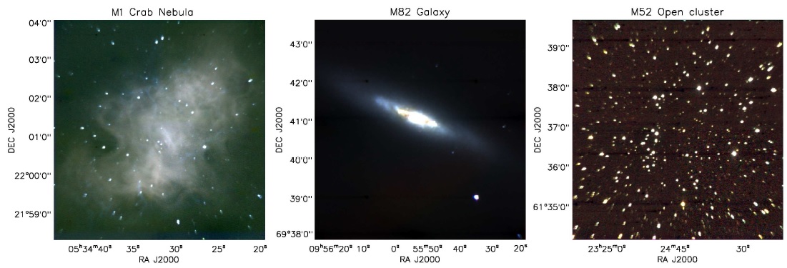
Fig. 7 Three-color composite images of CANICA observations of different objects obtained in J (green), H (blue) and K' (red) broad-bands. The images show both point and extended sources for a full FOV of 5.5 ×5.5 arcmin2. The first image displays the Crab Nebula. The middle image displays the M82 galaxy, and the last image displays M52, an open cluster. The color figure can be viewed online.
A considerable number of observations were dedicated to study a catalog of Hii galaxies with the aim of determining the luminosity functions from NIR photometry and to understand their evolution and star formation history. A brief summary of the project is described in Recillas et al. (2005). NIR surface photometry was employed for a sample of barred galaxies observed with CANICA to study their properties. Results are presented in Gadotti et al. (2007).
Multiwavelength studies of flaring and emission from high-energy AGNs/Quasar have been well complemented with CANICA data to better understand their origin and physical properties, see Foschini et al. (2012), Sokolovsky et al. (2014), Pacciani et al. (2014).
CANICA has been contributing regularly to a monitoring project of extragalactic gamma ray sources. Until now, over 250 NIR flares have been detected and reported in the Astronomers Telegram (e.g. Carramiñana et al. 2008; Carrasco et al. 2012, 2017).
7. SUMMARY
We have presented important aspects of the design, construction and control of the CANICA instrument. Over many years of operations, CANICA has been a great aid to NIR observations of various astrophysical topics. The camera serves as one of the main back-end instruments at the OAGH telescope, and accounts for the majority of telescope observing time (almost 60% in a year). CANICA is mostly used as monitoring and survey instrument for many projects. With a plate scale of 0.32arcsec/pixel and FOV of 5.5 × 5.5arcmin2 CANICA operates as a versatile instrument for both point and extended sources performing deep medium-field observations in the NIR.

