Introduction
On September 2017, Mexico was severely affected by two strong earthquakes of great magnitude; which generated large economic and human losses (Galvis et al., 2017). Buendia and Reinoso (2019) reported statistics of damages generated in the states of Mexico, Puebla, Morelos and Mexico City. They found that medium- and low-rise structures were the most affected; and that structures in corners, with torsional effects, with soft storeys and with geometric irregularities were the most affected. On the other hand, Pujol and Rodriguez (2019) reported damages observed in non-structural walls in Mexico City. They showed that severe damages occurred at small inter-storey drift ratios. Therefore, they recommended using an inter-storey drift ratio limit of 0.8% for design purposes in order to reduced non-structural and structural damages. Rodriguez (2019) showed that cumulated damage was also a significant factor that increased damages and triggered collapse in several cases.
After the observed damages, the need for finding innovative solutions to improve structural safety and mitigate damages has been exposed, especially in poor and developing regions. One of the most effective solutions to achieve adequate safety levels is the use of passive dissipation devices, such as buckling-restrained braces (BRBs). These devices have largely been tested (Merrit et al., 2003; Black et al., 2004; Tremblay et al., 2006), demonstrating their great capacity to dissipate large amounts of energy while protecting structural systems (e.g. Guerrero et al., 2017a & b; Fahnestock et al., 2007; Mazzolani et al., 2009; Di Sarno and Manfredi, 2012). As an example, Guerrero et al. (2016a) conducted shaking table tests on a steel building model in Mexico, concluding that BRBs reduced inter-storey drift demands and input energy significantly. One of the main advantages of BRBs is that they can act as structural fuses, i.e. disposable devices that can be replaced after an earthquake without interruption of the building’s functionality. Unfortunately, this type of devices is rarely used in developing countries like Mexico, mainly because they are often expensive proprietary devices, or because of the lack of knowledge in poor and developing regions. As a result, and similar to Palazzo et al. (2009), the need for developing a patent free dissipation device is urgent to help such regions to improve their building’s seismic safety; a right that should be granted for all human beings.
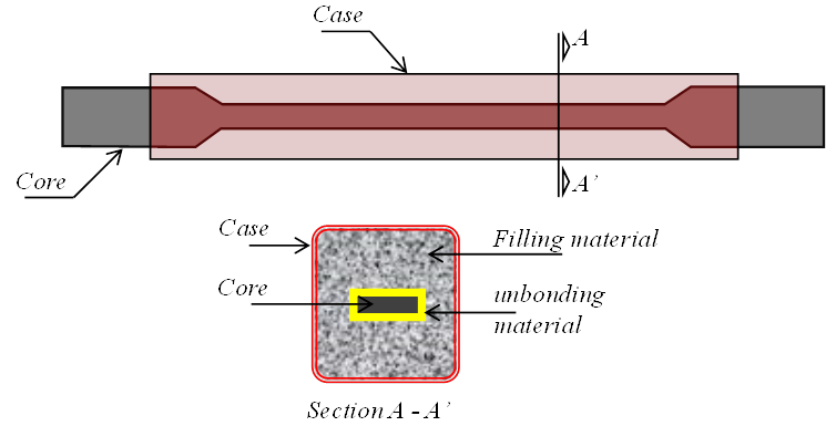
Although there are several variations, e.g. Uang and Nakashima (2004) and Della Corte et al. (2015), buckling-restrained braces (BRBs) are typically composed of a metallic core and a case (Figure 1). The core is made weaker in the middle zone (with the intension of concentrating plastic deformations) and stronger in the connecting ends (to ensure linear-elastic behavior in the connections to the structure). The case is filled up with concrete or mortar, which is provided to avoid buckling of the core under compressive loads. Also, and in order to avoid direct interaction between the core and the filling, an unbonding material is located between them.
The device proposed in this paper is also a BRB. It has been developed at the National Autonomous University of Mexico (UNAM) with the intension of having a low-cost, low-tech device, suitable for medium-to-low rise structures. The main advantages of the proposed device are: 1) it is made of conventional construction materials available in most regions of Mexico, Latin America, and developing countries around the world; 2) it can be fabricated with non-specialized labor using conventional tools; and 3) its dissipation capacity is similar to that of commercially available BRBs. These advantages are considered enough to foster its massive use in developing countries prone to seismic hazard.
This paper starts by describing the proposed device features, namely: composing parts and fabrication process. Then, its behavior under seismic loads is presented in terms of experimental hysteretic response and cumulated ductility demands. The results show that the proposed device has an excellent behavior, i.e. it has stable hysteretic loops and it is capable of dissipating large amounts of energy. As a consequence, it can be said that the proposed dissipation device is reliable and can be used massively in new and existing structures.
Features of the proposed device
Composing parts
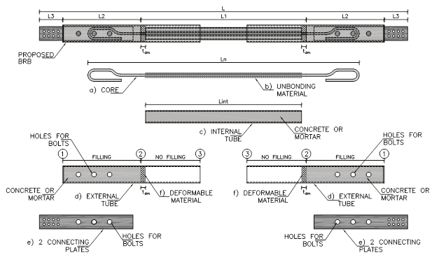
Figure 2 shows the composing parts of the proposed device. They are described as follows:
Core. It consists of a steel bar, which is bended to form hooks in its ends to provide anchorage. In Mexico, steel bars are commonly available on different steel resistances, such as: ASTM A36 (f y =250 MPa), ASTM A992 (f y =350 MPa), and ASTM A615 (f y =420 MPa). Core bending and anchorage recommendations are provided in the next section. It is significant to mention that more than one bar can be provided in the core. A maximum of four bars is advisable.
Unbonding material. This can be any soft material that covers the steel bar and avoids direct contact between the core and the filling material of the case. A polymeric material can be used (e.g. rubber, oilskin, etc.). The main function of the unbonding material is allowing axial deformations of the core under tension and compressive loads. As a recommendation, and based on previous studies (e.g. Guerrero, 2016; Guerrero et al., 2018a & b), this material thickness should be between 10% and 20% of the bar diameter. It is highlighted that a thinner thickness of the unbonding material could generate negative effects on the device performance. These effects could happen because, as the core increases its cross-sectional area under compressive loads due to the Poisson effect, large radial forces and friction would be induced in the case. Unexpectedly large demands in the case could generate global or local damage in it, which could generate poor performance of the device.
Internal tube. This is a metallic tube, which after the metallic core has been located inside it, it is filled up with plain concrete or mortar. Concrete or mortar must have, at least, the following characteristics: 1) plain concrete Class I (MCBC, 2017) with nominal strength of f’ c =25 MPa; 2) cement-sand mortar type I, in agreement with MCBC (2017), in proportion of 1 to 3.
External tubes. These are two metallic tubes with a cross-section slightly larger than that of the internal tube, in such a way that the former ones can slide over the latter. Note in Figure 2 that one part of the external tubes is filled up with concrete or mortar (see points 1 and 2), while other part remains empty (from point 2 to 3). It should also be appreciated that the external tubes have orifices. The orifices go through in order to locate bolts or fasteners that provide continuity from the core to the connecting plates.
Connecting plates. They are four plates that join the device to the hosting structure. They have two types of holes: 1) those that join them with the core and give continuity; and 2) those that join the BRB with the hosting structure. It shall be noted that the connecting plates are put inside the external tubes, and that they are mostly covered with mortar or concrete.
Deformable material. This material is expanded polystyrene or any soft material that can be easily deformed under the action of axial loads on the device. It is located inside the external tubes and has a thickness referred as t dm . It works as a formwork as its function is to separate the internal tube and the filling material of the external tubes.
Fabrication
The fabrication process is as follows:
Hooks of the core. To provide the hooks in the core ends, as well as the development length, it is recommended to follow the specifications provided by the local design codes. As an example, the complementary rules for concrete design of the Mexico City Building Code (MCBC, 2017) require to calculate a development length, L d , as the product of the basic development length, L db , and modification factors that take into account the features of the steel bar and the anchorage material. While the most significant modification factors are listed in Table 1, the basic development length is calculated as (MCBC, 2017):
Table 1 Development length modification factors.
| Feature | Factor |
|---|---|
| Lightweight concrete | 1.3 |
| Plain bars (non-corrugated) | 1.9 |
where d b is the bar diameter in mm, and f y and f’ c are the nominal yielding stress and the concrete nominal resistance, respectively, in MPa.
Figure 3 shows that the Mexico Building Design Code (MCBC, 2017) requires a development length, L d , larger than 150 mm or 8d b . It also requires that the straight segment after the hook to be larger than 4d b (i.e. t r ≥ 4d b ). In this paper, the recommended limits are increased according to experimental observations (see García, 2020). Therefore, the following limits are suggested in order to ensure stable plastic behavior of the core:
where d b is the bar diameter in mm, L d is the development length, and t r is the straight segment after the hook.
Regarding the hook radius, r
d
, it should be greater than
2. Unbonding material. This material covers the core bar in the length L 1, as seen in Figure 1. The unbonding material could be any deformable material that avoids direct contact between the core bar and the filling concrete or mortar located inside the internal tube. A material that has given great results is polyisobutylene (or butyl rubber) which is found, for example, in tyre inner tubes. In fact, these authors have cut strips from used inner tubes to fabricate prototype BRBs, which, in turn, results environmentally friendly as a waste material is reused to produce a device beneficial to society.
3. Filling of the internal tube with mortar or concrete. Once the core has been covered with the unbonding material in a length equal to L 1, it is located inside the internal tube, which is then filled with concrete or mortar. Note that the concrete resistance does not need to be high, since a concrete strength of 25 MPa is enough. As an example, these authors have used cement-sand mortar as a filling material with a proportion of 1:3 obtaining successful results during laboratory tests of prototype BRBs. A helpful advice is filling the tube vertically. While the bottom end is sealed, the filling material is poured from the top end. This provides good control during the filling process.
4. Placing the deformable material. Once the filling material has reached a manageable resistance (about three days after the pouring), the deformable material must be located at each end of the internal tube. This material could be polystyrene or any deformable material. Its cross-section shall be the same as the cross-sectional dimensions of the internal tube. Its thickness shall be at least the maximum expected deformation of the device; this fact will be addressed later in section 3.4. Since the deformable material is located at both ends of the internal tube, the deformation capacity will be as twice as the maximum expected deformation demand. To achieve the desired thickness, more than one layer can be located. In order to fix the deformable material to the internal tube properly, abundant sticky tape shall be used.
5. Introducing the external tubes and locating the connecting plates. The internal tube and the core are introduced inside the external tubes. The four connecting plates are also located. Everything is aligned so that the fixing bolts can be located as indicated in Figure 2.
6. Filling external tubes with concrete or mortar. As indicated in Figure 2, the filling material is located between points 1 and 2. Again, it is recommended to fill the external tubes vertically. In this regard, it is recommended to fill one tube first and, after two or three days, the other one. Once the filling material has reached a manageable strength (say three days after the last pouring), the devices can be installed in the hosting structure. More details about the fabrication process can be found in García (2020) and Sánchez Arriaga (2020).
Connection to hosting structure
Connection to hosting structure is an important issue that must be considered within the design process to avoid unexpected failures before the device dissipates energy. In the proposed device, the two connecting plates, located at each side of the device, are connected to a gusset plate. Both, the connecting and gusset plates must be designed using capacity design principles. The BRB ultimate strength capacity, in tension and compression, factored by a safety factor of (say) 1.25, must be considered to design connecting and gusset plates. Furthermore, the use of shim plates with stiffeners are recommended to avoid out-of-plane deformation in the connection. As an example, in Guerrero et al. (2018a), angle profiles were used as shim plates on an experiment to connect the proposed BRB to a reinforced concrete structure subjected to shaking table action. It was seen that the connections performed adequately.
More recently, García (2020) and Sánchez Arriaga (2020) conducted experiments on the proposed BRB. They used four connecting plates (two on each side) welded laterally to the external tubes. Since the connections were designed using capacity design principles, they performed well during the experiments. More details about the connections are provided in García (2020) and Sánchez Arriaga (2020).
Experimental behavior
To validate the experimental behavior of the proposed device under seismic loads, a prototype was fabricated and tested in laboratory. The tests were conducted at the Institute of Engineering of the National Autonomous University of Mexico in January 2018. This section presents the details and results of the experiment.
Experimental setup
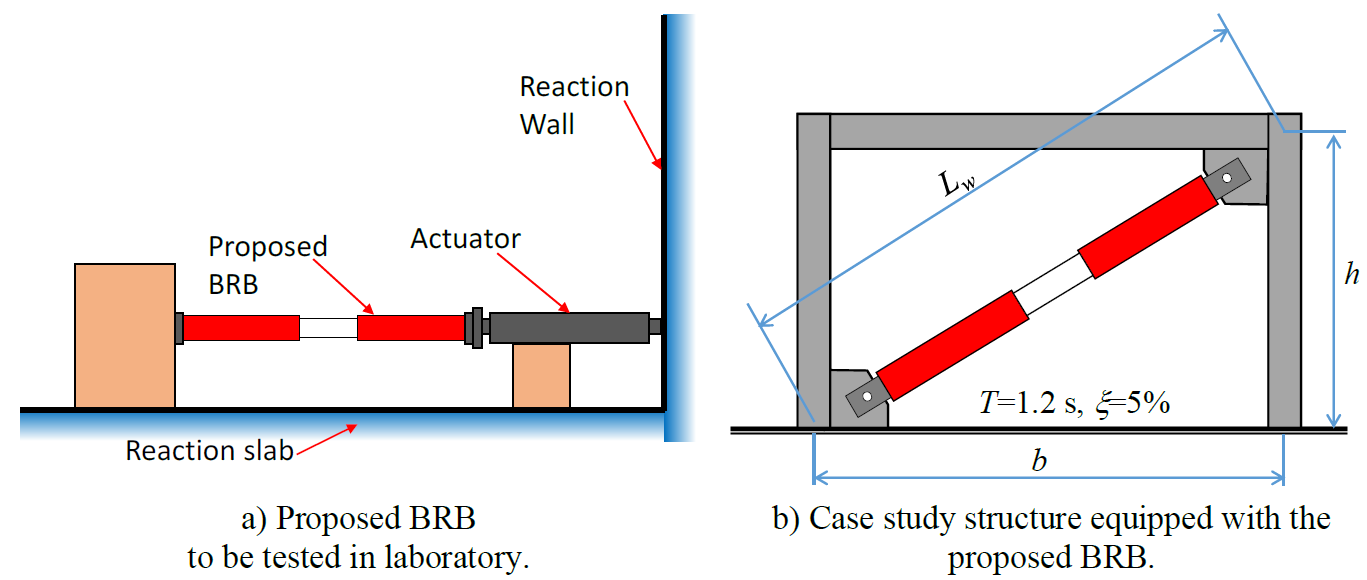
A prototype device was fabricated following the procedure described in section 2. It was subjected to a history of controlled axial displacements in an arrangement like that shown in Figure 4a. The axial displacements were calculated using the 2D frame of Figure 4b subjected to a seismic ground motion, which is described later in section 3.3. The hosting structure had a period of vibration of T=1.2 s and a damping ratio of =5%. Elastic response of the frame was assumed while nonlinear behavior of the BRB was considered. Both, the storey height and bay width were 2.33 m. Fixed base was assumed in the model while the BRB was assumed as pinned-connected. The beam was considered infinitely stiff and the columns had a second moment of area of I = 1000 mm4. The total mass was 213 N.s2/mm. The frame material was steel with an elasticity modulus of 200 GPa. Although these properties were selected arbitrarily, the period was considered representative of medium-rise structures in downtown Mexico City. The frame structure, equipped with the proposed BRB, was modelled in the finite element program Opensees (2014). In order to evaluate the behavior of the proposed BRB under different levels of ductility demand, the ground motion was scaled in amplitude at different intensities. The results of the BRB in terms of hysteretic behavior and cumulative ductility demands are presented in section 3.4.
The properties of the tested device were the following:
It had a total length of L=3.3 m and a core length of L n =2.05 m.
The core consisted of a plain bar with a diameter of 12.7 mm.
The material had a strength resistance of 350 MPa.
The internal tube was a HSS 64x64x3 steel profile, available in Mexico. It had a length of 800 mm. It was made of steel ASTM A500.
The two external tubes were HSS 102x102x3 with a length of 1.5 m each, made of steel ASTM A500.
The filling material was made of a white cement-water mortar.
The unbonding material consisted of polyisobutylene; in fact, for this study, strips of used tyre inner tubes were cut and used to wrap the core to provide a thickness of 2 mm.
The deformable material was expanded polystyrene with a thickness of 19 mm.
Figure 5 shows images of the tested device during its fabrication stage. It should be highlighted that all the materials, used to fabricate the device, are available in most regions of Mexico and they are commonly accessible in developing countries. Another advantage of the device is that only minor tools and non-specialized labor are needed for fabrication.
Testing program
A slow history of seismic displacements, calculated for the structure of Figure 4b, was applied. The aim was evaluating expected peak and cumulated ductility demands on the proposed BRB under different levels of seismic intensity. It is clarified that, as far as the authors is concerned, there are no standard recommendations for conduct such type of tests. Therefore, the results must be interpreted under that light. Four tests were conducted. The tested device was subjected to the program described in Table 2. While the first test was carried out to keep the device within its linear-elastic behavior (i.e. target ductility of 1 and inter-storey drift ratio of 0.0025 in the structure), the others tests were conducted to reach inelastic behavior (i.e. target ductilities of 2, 4 and 8; and inter-storey drift ratios on the structure of 0.005, 0.010 and 0.020, respectively).
Table 2 Testing program.
| Test | Target ductility | Target displacement | Inter-storey drift ratio | Description |
|---|---|---|---|---|
| 1 | 1 | 4 mm | 0.0025 | Linear-elastic response |
| 2 | 2 | 8 mm | 0.005 | Inelastic response for low ductility |
| 3 | 4 | 16 mm | 0.010 | Inelastic response for high ductility |
| 4 | 8 | 32 mm | 0.020 | Inelastic response for severe demands |
Earthquake ground motion
The ground motion, used for calculating the axial displacements imposed to the proposed BRB, was that recorded at the SCT station during the 19/Sep/1985 Michoacán, Mexico Earthquake. The E-W component was used in the 2D model. Figure 6 shows the ground motion and its 5%-damped elastic pseudo-acceleration spectrum. It is significant to mention that the recording station is located in the lakebed zone of Mexico City, which is characterized by very soft soil deposits having shear wave velocities lower than 180 m/s and water contents up to 400% (Singh and Suárez, 1986). As can be deducted from Figure 6, the ground motion has a very long duration and well-defined periods of vibration, which is characteristic of the ground motions at the lakebed zone of Mexico City. Figure 6b shows that the response spectrum has two well-defined peaks at 0.7 and 2 s, which are, respectively, the second and first predominant periods of the soil at the location of the SCT station.
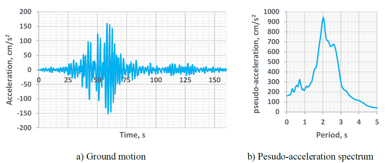
Figure 6. E-W component of the ground motion recorded at SCT station during the 19/Sep/1985 Michoacán, Mexico Earthquake
It is significant to mention that this ground motion was selected because, according to Buendia and Reinoso (2019), most of the affected structures during the 2017 earthquakes were medium- to low-rise buildings, which tend to have shorter periods than the soil’s predominant period of vibration at that location. Even when such structures were not in the resonance zone of the spectra, they were significantly damaged. These affectations may be attributed to the fact that inelastic displacements are significantly larger than the elastic counterparts for short-period structures (structures with shorter periods than the soil’s predominant period of vibration). Therefore, the selected structure of Figure 4b, with period of vibration of 1.2 s, may be considered representative of structures affected during the 2017 earthquakes.
Results
Hysteresis curves
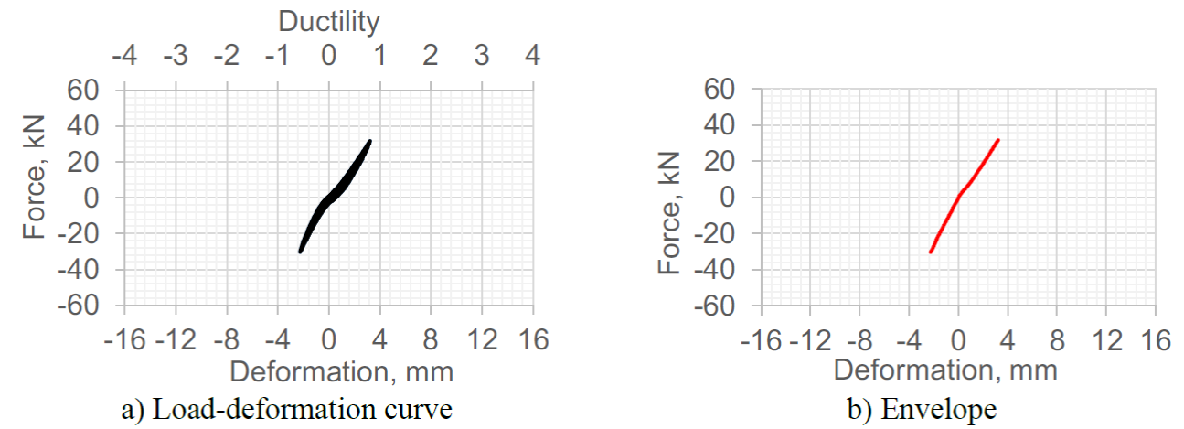
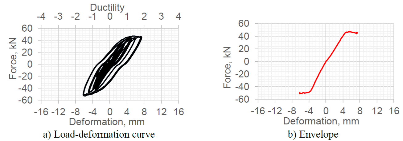
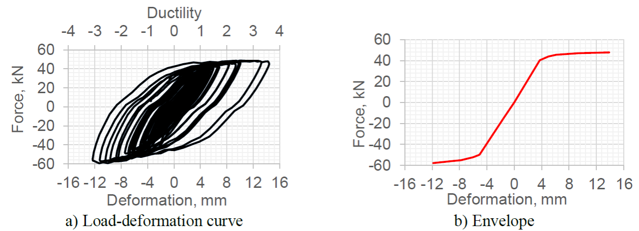
Figures 7 to 9 show the load-displacement curves and their envelopes for tests 1 to 3. While the vertical axes show the loads on the device, the horizontal axes show both the applied displacements (bottom) and ductility demands (top). In Figure 7, corresponding to test 1, it is seen that the ductility demand was slightly smaller than unity, which means that the device remained within its linear-elastic behavior. In Figures 8 and 9 it is observed that the ductility demands were close to 2 and 4, respectively. In both figures a stable inelastic behavior is observed, a fact that demonstrates the device reliability under such ductility demand levels.
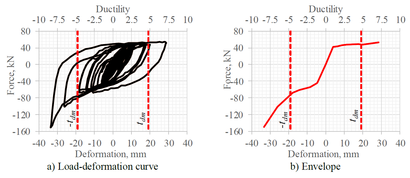
Test 4 was conducted with the intention of understanding the behavior of the proposed device under severe inelastic demands. For that purpose, the seismic intensity was increased so that the displacement demands on the prototype structure generated a maximum ductility demand of 8 on the BRB. Figure 10 shows the experimental load-deformation curve and its envelope. It can be observed that, although the device presented stable hysteretic behavior, its compression capacity increased significantly.
The asymmetric hysteresis loops obtained from test 4 may be of great concern for regions with large earthquake events. This behavior is undesirable because such increase of capacity can result in damage to connections, foundation or other structural elements. Note that the capacity only increased under compressive but not under tension loading. This occurred because the deformable material, t dm , as defined in Figure 2, shrank under compressive loads till the mortar of the internal and external tubes touched, which made them take loads. In order to avoid the increase of capacity on the compression side, there are three options that the designer could follow:
Provide a deformable material thickness large enough to avoid contact between the mortar of the internal and external tubes. For the tested BRB, the deformable material had a thickness of 19 mm on each side, which is a total of 38 mm. Analyzing Figure 10, it can be seen that, for displacement levels of ±19 mm, the device shows an almost symmetric behavior, i.e. it has similar capacity in tension and in compression. However, when the displacements go beyond that value, the capacity in compression increases dramatically because not only the core but also the internal tube starts taking compressive loads. This effect is clearly seen in Figure 11, where the state of deformation of the internal tube right after the end of test 4 is shown. Based on the results observed in Figure 10, it is recommended that the deformable material thickness, t dm , should be equal to or greater than maximum expected deformation on the device.
Limit the structure lateral deformation. Designers using the proposed device must control the structures’ lateral displacement demands. A maximum inter-storey drift ratio of 0.01 may be an advisable design limit, since test 3 (where a ductility of 4 and an inter-storey drift ratio of 0.01 were demanded) showed very good results.
A combination of bullets 1 and 2.

Figure 11. State of deformation of the device under severe inelastic demands (after the end of test 4)
Cumulative ductility demands
One of the most accepted parameters to compare the plastic capacity and plastic demands of a hysteretic device is the cumulative ductility demand (CDD). According to Merrit et al. (2003), the CDD is calculated as:
where F y and u y are the yielding axial force and displacement on the device, while E s is the hysteretic energy, defined as:
being F and u the axial forces and displacements on the device during the seismic response.
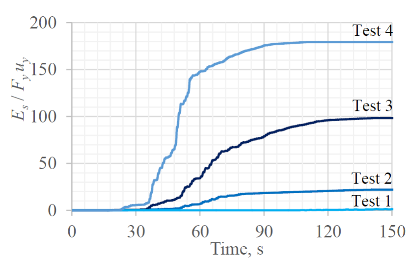
Figure 12 shows the cumulative ductility demands for tests 1 to 4. While the CDD is negligible for test 1, it can be considered low for test 2 (around 20), high for test 3 (around 100), and very high for test 4 (around 180). According to Black et al. (2004) and Fachnesyock et al. (2007), the cumulative ductility demands shown on Figure 12 are well below cumulative ductility capacities of typical BRBs, which can achieve capacity values between 300 and 1000. Actually, adding the CDDs shown in Figure 12 for the four tests, the total CDD is around 300. This observed capacity implies that the proposed device is reliable to protect structures under severe seismic demands. It is significant to mention that an experimental study on 12 samples of the proposed device, conducted recently by García (2020), showed an average cumulative ductility capacity of 322, which demonstrates the reliability of the proposed device.
Desing
Stiffness
Stiffness and strength are the most important parameters during the designing process in order to account for their contribution to the hosting structure. In this section, the stiffness calculations are presented, while those related to the strength are calculated in section 4.2.
Theoretical stiffness
According to Black et al. (2004), the stiffness of a typical BRB can be calculated with:
where K BRB is the stiffness of the BRB, K n is the stiffness of the core’s weaker part and K f is the stiffness of the connection ends at each side of the BRB. K n and K f can be calculated as:
where A n and E are the weaker cross-sectional area of the BRB and the elasticity modulus of the core, respectively, L n is the core length, A f is the connection ends cross-sectional area and L f the connection ends length. For the proposed BRB, E= 200 000 MPa, A n =127 mm2, L n =2050 mm, A f =1300 mm2, and L f =625 mm, which gives K n =12.39 kN/mm, K f =41.63 kN/mm. Therefore,
On the other hand, in practical applications the stiffness of a BRB is calculated as (Guerrero et al., 2016b):
where A n and E have already been defined; L w is the distance between the working points (i.e. the distance between the two joins from center to center); and f k is a factor that takes into account the geometric and mechanical variations of the BRB along its length.
Since all the parameters of Equation (9), except f k , were known during the specimen test, the results of Equation (5) are used to determine the value of f k , this is:
Experimental and theoretical comparison
Now, the results of Equations (8) and (10) are compared to the corresponding experimental values. For that purpose, the maximum values in tension and compressive loads from test 1 are used to estimate the BRB stiffness (K BRB ) as follows:
where F max and d max are the peak force and displacement in tension, while F min and d min, are the peak force and displacement in compression. The error between the results of Equations (8) and (11) is less than 5%.
To calculate the value of the stiffness factor, f k , for the proposed BRB, the following equation is suggested in this paper, which neglects the flexibility of the connection ends:
where L n was defined in Figure 2 and L w in Figure 4. Since L w =3300 mm and L n =2050 mm:
Comparing the results of Equations (10) and (13), it is seen that the error is 5.9%, which is deemed acceptable for practical purposes.
In summary, it can be said that, for practical purposes, the stiffness of the proposed BRB can be calculated using Equation (9), while the stiffness factor using Equation (12).
Strength
For BRBs, three levels of strength must be calculated, namely: yielding strength, maximum strength in tension, and maximum strength in compression. The yielding strength is similar in tension and compression; however, this is not true for the ultimate strengths, since the capacity in compression is often higher than that in tension, as can be deducted from Figures 9 and 10.
Yielding strength
According to the Mexico City Building Code and its complementary rules for steel structures design (2017), the yielding strength in tension (T R ) and compression (C R ) of a BRB is calculated as:
where
For tested device, the nominal yielding stress was f y =350 MPa; therefore, the code yielding resistance was:
Note that the strength calculated using Equation (15) is, on average, 15% smaller than the yielding values observed in Figures 8, 9 and 10. This normative resistance resulted smaller than all the measured yielding resistances, which is regarded appropriated as it is conservative for design purposes. Also, note that there are some variations between the measured yielding resistances, which shows that there is uncertainty associated to the expected resistance of steel members. Although variations exist, it seems reasonable to use Equation (15) to calculate a nominal yielding resistance of the proposed BRB.
Ultimate strength in tension
The ultimate strength resistance in tension is calculated as (Merrit et al., 2003; Kerting et al., 2015):
where f ye is the expected yielding stress of the core’s material, A n is the core cross-sectional area, and ω is a factor that takes into account the increase of strength due to strain-hardening. Since ω is unknown for the proposed device, it was calculated with the help of Figure 9b, by dividing the maximum force in tension by the measured yielding strength. The result was ω =1.14. This value is within the range of commercially available BRBs (see for example: Merrit et al., 2003). In a recent statistical study by García (2020) on the proposed device, 18 BRBs were tested. The average vale of ω resulted, again, 1.14, with a coefficient of variation of 0.03. Therefore, ω=1.14 can be used with confidence for design purposes.
Ultimate strength in compression
The ultimate strength resistance in compression is calculated as (Merrit et al., 2003; Kerting et al., 2015):
where β is a factor that takes into account the increase of resistance in compression due to Poisson effect and friction within the BRB (Guerrero et al., 2018b), and all the other parameters have already been defined.
For the tested device, the value of β was calculated again with the help of Figure 9, by dividing the maximum load resistance in compression by the maximum load in tension, which resulted β =1.21. This value resulted slightly above typical values when compared to commercially available BRBs (see for example: Merrit et al., 2003). After testing 18 samples of the proposed BRB, García (2020) showed that the average value of β can be taken as 1.13 for design purposes.
Conclusions
The experimental behavior of a proposed low-cost, low-tech BRB was studied under seismic loading. Its composing parts, fabrication procedure and design recommendations were given. The following conclusions are formulated:
The proposed device can be fabricated with non-specialized labor using common tools and construction materials available in many developing countries.
It was observed that the device shows stable hysteretic behavior when subjected to low and intensive seismic loading. It managed to accommodate large peak ductility demands close to 8 without difficulties. It also was capable of resisting cumulative ductility demands of around 300, which are several times larger than expected demands during strong earthquake events.
The deformable material plays a key role in the behavior of the tested BRB when subjected to compressive loads. As observed, the capacity in compression could become very large, which could result in damage to connections or other elements. In this context, and as a recommendation, the thickness of the deformable material, t dm , should be at least the maximum expected deformation of the BRB. Additionally, by controlling inter-storey drift ratios below 0.01, excellent performance of the proposed device can be expected.
Since the experimental and analytical stiffness were similar (with errors smaller than 5%), Equations (9) and (12) are recommended to calculate the device stiffness.
Similarly, the device strength can be calculated using Equations (15) to (17), taking factors ω and β as 1.14 and 1.13, respectively, for design purposes.
It is significant to mention that the findings discussed in this paper are applicable to the studied specimen. Any variation must be validated in laboratory to understand its behavior. The reader is referred to García (2020) and Sánchez Arriaga (2020) for additional information about the proposed BRB.


 text new page (beta)

