


 nova página do texto(beta)
 Inglês (pdf)
 Artigo em XML
 Referências do artigo
 Enviar este artigo por email
 Citado por SciELO
  Similares em
SciELO
Similares em
SciELO 
 Permalink
Introduction
Mexico City, especially in the lakebed zone, possesses higher levels of seismic risk than many other cities around the world. This is reflected in the return periods for earthquake design which are lower than those in other standards, i.e. the equivalent return period for design in some zones of Mexico City is as low as 125 years (Reinoso and Jaimes, 2005; Rosenblueth et al., 1988). Structures located in these zones are likely to be subjected to large ductility demands during earthquakes, due to the characteristics of the ground motions of the very soft soil (Bojórquez and Ruiz, 2004, Arroyo and Ordaz, 2007, Teran-Gilmore and Bahena, 2008). The use of passive dissipation technology (like BRBs), in such structures, will help to effectively reduce the levels of seismic risk and their lifecycle costs, while increasing their reliability (Montiel and Teran-Gilmore, 2011).
Buckling-restrained braces (BRBs) are a type of passive seismic dissipater and represents one of the major developments in seismic design in recent years. Although there are several configurations (as summarised by Xie, 2005), it commonly consists of a rectangular steel core and a case (Figure 1). The core is weaker in the central zone so that the plastic deformations under cyclic loading are concentrated there. The case is often made either of a steel tube filled with concrete (e.g. Merrit et al., 2003; and Black et al., 2004), or all made of steel (e.g. Della Corte et al., 2014; and Formisano and Mazzolani, 2015). The function of the case is to prevent buckling of the core so that the device has similar capacity in tension and compression (Figure 1d). An unbounding material is located between the core and the case to avoid direct interaction. Several enhancements to BRBs have been proposed recently in order to improve their implementation in practical applications (e.g. Iwata and Murai, 2006; Zhao et al., 2010).

Experimental tests on buckling restrained braces (BRBs), as isolated members, have demonstrated that these devices possess high energy dissipation capacity by means of stable and symmetric hysteretic loops when they are subjected to cyclic loads, e.g. (Merrit et al., 2003; Black et al., 2004; Uang and Nakashima, 2004; Iwata and Murai, 2006; Zhao et al., 2010). However, experiments are still needed in order to corroborate their good behaviour when located in actual building frames subjected to seismic loads. Unfortunately, most of the current studies have been conducted under quasi-static loading (e.g. Della Corte et al., 2014; and Formisano and Mazzolani, 2015). Although valuable information has been obtained, experiments under dynamic loads are desirable. In this regard, shaking table tests are significant because they allow assessing the dynamic behaviour of structures under conditions similar to those found in actual earthquakes (Benavent-Climent and Escolano-Margarit, 2012). Unfortunately, the number of such tests is still limited and conducted under particular types of seismic excitation. For example, Vargas and Bruneau (2009) tested a three-storey one-bay steel model, in a scale of 1/3, equipped with BRBs under a synthetic record on a shaking table in the USA. Under that synthetic record, the frame presented stable performance when the BRBs were introduced. Reductions of the lateral displacements and inter-storey drifts by 70% and an increment of the damping ratio, from 2% to 5%, were appreciated. Kasai et al. (2010) tested a full-scale five-storey steel building frame equipped with four different types of dampers (including BRBs) on a shaking table in Japan. The frame was subjected to the Takatori ground motion of the 1995 Kobe earthquake. Under such ground motion, they showed that the inclusion of dampers reduced the displacements, storey shears and absolute floor accelerations. They reported that the damping ratio remained unchanged when the model was subjected to low-intensity white noise input, with and without BRBs. However, for seismic input, an increase of the damping ratio, from 2% in the bare model to about 9% in the equipped structure, was reported. It was also observed that the damping ratio increased with the seismic intensity. Hu et al. (2010) tested a full-scale pinned-connected steel frame equipped with BRBs under the El Centro ground motion. They found that the BRBs performed well under a high seismic level motion; drift demands were well controlled and no damage was encountered in the structural elements of the frame. Hence they recommend the use of BRBs in seismic zones.
From the literature review, it is appreciated that past shaking table studies have been conducted for particular types of excitations. These specific conditions may not allow generalisation of the results. Therefore, it is of interest to assess the behaviour of structures equipped with BRBs subjected to low-frequency ground motions, such as those recorded in the lakebed zone of Mexico City, because this system may constitute an alternative to help to reduce or mitigate damages observed in the past in this region of the World.
This paper presents the results of shaking table tests of a five-storey building model equipped with BRBs undertaken in Mexico. The tests were focused on assessing the performance of a model frame when subjected to ground motions which are appropriate for the lakebed zone of Mexico City. In the following sections, the test setup of the studied model and the main results, from the free vibration and shaking table tests using white noise and seven actual seismic records, are presented. The results demonstrate the advantages of fitting these devices in buildings, because the response parameters (namely: lateral displacements, inter-storey drifts, floor velocities, floor accelerations, and energy contents) were all significantly reduced. It is highlighted that the experiments were conducted on a shaking table at the Institute of Engineering of the National Autonomous University of Mexico (UNAM).
Test setup for the frame building model
The model
The one-tenth scale model building, as shown in Figure 2, has a height of 1450 mm, a width of 600 mm and a depth of 300 mm. It is composed of five storeys and is made of ASTM A-36 steel - which has nominal and expected yielding stresses of 250 MPa and 282 MPa, respectively, as reported by Merrit et al. (2003). The cross-sections of the members are given in Table 1. Since the main objective of the tests was to protect the main frame, the structural elements (beams and columns) were designed to remain elastic, while all nonlinear response was concentrated in the BRBs. More details of the design are described later. Two mass scenarios were considered: 1) 150 kg/m2 on the floors one to four and 145 kg/m2 on the fifth floor; and 2) 417 kg/m2 on the floors one to four and 412 kg/m2 on the fifth floor.


BRBs used in the tests
Due to the scale of the test frame model (1/10), there are no commercially available BRBs. Therefore, they had to be fabricated specifically for this study. The composition and dimensions of a typical BRB used in this study are shown in Figure 3.

Each BRB consists of a soft galvanised steel core, an encasing sleeve and two connection ends. The core steel had a yielding stress and elasticity modulus of fy =405 MPa and Es =118,725 MPa, respectively, obtained from laboratory tests. The core was wrapped with 0.2 mm polytetrafluoroethylene (PTFE) film, as unbonding material, to separate the core and mortar of the case. The two ends of the core were placed and fixed in the connection ends - which consist of two steel tubes and an epoxy material.
It is significant to mention that: a) the filling material consisted of a cement and sand mortar in proportion of 1:2 - which has an approximated resistance of 15 MPa; b) the epoxy material consisted of a mixture of an epoxy resin and a catalyst - which reaches a tensile resistance of 40 MPa; and c) the steel tubes of the case and the connection ends were square cross-sections of 13 mm x 13 mm and 19 mm x 19 mm, respectively, with wall thickness of 1 mm. Note that the cross-section of the case is smaller than that of the connection ends, in such a way that the connection tubes can cover a part of the case in order to avoid out-of-plane deformation of the BRBs.
The cross-sections of the cores were circular wire rods with diameters of: 1.6 mm (for BRBs type 1 used in the first two storeys.); and 1.2 mm (for BRBs type 2 used in the next three storeys). While more details of their design are described in the next section, the experimental response of a simple BRB type 1, as isolated member subjected to quasi-static sinusoidal displacement-controlled tests with amplitude of 0.5 mm, 1.0 mm and 2.0 mm, is shown in Figure 4. While quasi-elastic behaviour is observed for a displacement amplitude of 0.5 mm, slightly nonlinear response is observed for a displacement amplitude of 1.0 mm, and highly nonlinear behaviour of seen for 2.0 mm. These observations will be further discussed later.

On the other hand, the connections of the BRBs to the structure consisted of gusset plates, of ASTM A-36 steel, fastened with bolts. Two splice plates were used to connect each BRB end to each gusset plate. To join them, four 6.4 mm diameter bolts were used. In this case, the splice plates possessed large cross-sectional areas (60 mm2 each), to avoid unexpected failures in the connections before the cores of the BRBs yielded.
Design of the BRBs
First, the capacity of the bare frame model was determined. Then, the BRBs were designed to increase the stiffness and lateral resistance of the model.
From a pushover analysis, and using the expected properties of the materials, the lateral resistance of the bare frame, normalised by its total weight (for the second mass scenario), was estimated to be Vy
/W=0.18. Also, from eigenvalue analysis, its period of vibration was T=0.31 s - which according to the similitude laws (presented in the next section) corresponds to a full-scale period of
Since the period was considered long, and the strength low, for typical five-storey buildings located in the lakebed zone of Mexico City, BRBs were provided to the model. The design method proposed by Guerrero et al. (2016), which is based in the control of the lateral displacements, was applied. After a few iterations, it was observed that BRBs with cross-section areas of 2 mm2 (in storeys one and two) and 1.1 mm2 (in storeys three to five) provided satisfactory control of the lateral response while the main frame remained within its elastic deformation range. Note that the cross-sections areas correspond to the diameters of 1.6 mm and 1.2 mm described in the previous section. The final period of vibration of the equipped model resulted T=0.22 s (or 0.70 s in full scale) and the normalised strength was Vy /W=0.38. It is seen that the BRBs increased the lateral capacity by 0.20W.
Similitude laws
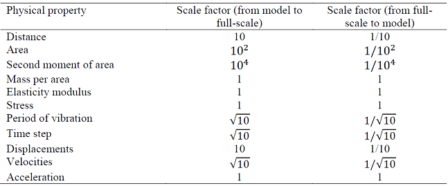
As previously highlighted, the scale of the test model was 1/10 due to restrictions of cost and capacity of the test equipment. Therefore, similitude laws were developed using the theory of modelling (Harris and Sabnis, 1999). They are listed in Table 2. As an example, it is observed that the physical quantities of distance and displacement have a scale factor of 10 to go from the tested model to full scale and a factor of 1/10 to go from full scale to the tested model scale. Similarly, the period and time step have factor of
Instrumentation and measured data
Three accelerometers were located on each floor: two in the longer direction (X) and one in the shorter direction (Y) (Figure 2d). Thus the responses in the X and Y direction and in the torsional direction could be monitored. Setra 141 accelerometers were used because of their high accuracy, output stability and measurement range (from static to 3000 Hz). The lateral displacements at each storey were estimated by double integration of the measured accelerations. To avoid unintended errors during the integration process, recommendations by Boore and Bommer (2005) were considered. No filtering, filtering between 0.1 and 20 Hz and between 0.5 and 20 Hz were tested. Figure 5a shows the 5%-damped elastic displacement spectra based on the accelerations recorded at the base of the model in one test. It is observed that none of the band-pass filters affected the response in the frequency range of interest between 1 Hz and 10 Hz. On the other hand, Figure 5b shows the transfer functions between the top floor and the base of the model, due to a white noise input. It shows that the band-pass filter between 0.5 Hz to 20 Hz eliminated the noise at low frequencies. Therefore, this filter was considered adequate, and errors in the estimation of the lateral displacements due to filtering may be considered negligible (Hudson, 1979). However, it is not possible to estimate permanent (or residual) displacements.

Seismic Input
Seven earthquake records were used to test the model (see Table 3). All seven were recorded in the lakebed zone of Mexico City, which is characterised by very soft soils, and they have dominant periods of vibration around two seconds. The time step on each record was scaled by a factor of

Design of the experiment
The input was applied in the longer direction of the model and in the orientation of the BRBs. The tests are summarised in Table 4 and described below:

In the first stage, the model with the first mass scenario was used for free vibration tests. An initial displacement was applied and then suddenly released to generate free vibration. The model without BRBs was first tested. Then, BRBs were introduced in the first storey and a free vibration test was conducted again. This was repeated until all five storeys of the model were fitted with BRBs. Finally the model was shaken using a (50 cm/s2 RMS) white noise in order to measure its dynamic properties in an alternative manner. Reduced levels of mass were used at this stage to avoid unexpected damage to the model and elements.
In the second stage, the model with the second mass scenario was used. The model was subjected to (50 cm/s2 RMS) white noise. Then, seven ground motion records were applied at the base, with seismic intensities of: pga = 0.10g, 0.15g, 0.20g and 0.25g, respectively. For the intensity of 0.10g, the model was tested with and without BRBs. For the other pga values, the model was fully equipped with BRBs in all storeys. Floor accelerations were measured in all tests. Then, the effects of the BRBs in the model were analysed.
Figure 5 shows the model used in the first stage of the tests and how the BRBs were gradually added to the model. Figure 7 shows the model with added mass (Mass scenario 2) in the second stage of the tests. The purpose of having the increased mass was: 1) to provide more realistic levels of mass; 2) to produce a longer fundamental period of vibration which generates larger displacements; and 3) to ensure that the BRBs go beyond their elastic limit to dissipate energy.


Experimental results
Free vibration test
Figure 8 shows the recorded accelerations at the top floor for tests 1a to 5a, as described in Table 4 and shown in Figure 5. It can be observed that the vibration of the model decayed quickly due to the contribution of BRBs. This was due to an increase in the damping and stiffness of the model structure.

The damping ratios for the first four cases were estimated by curve fitting to the first 10 oscillations of the measured data. For the last case, a white noise had to be induced in the model and the damping was estimated by balancing the damping energy equation (see next subsection). Figure 9a shows the damping ratio estimated for each case, in which the horizontal axis shows the number of pairs of BRBs used and the vertical axis the damping ratio. Similarly, Figure 9b shows the peak inter-storey drift demand for each pair of BRBs. It is observed that the inter-storey drift demands remained well below the yielding limit of 0.005, which is described later in Section “Inelastic behaviour of the BRBs”.
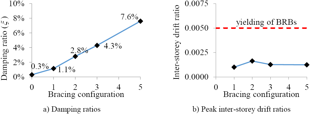
It is clear that the BRBs increased the damping significantly in the model and that the BRBs remained within their linear-elastic range. This is in agreement with observations by Vargas and Bruneau (2009). This finding may be significant because it is commonly assumed that BRBs do not provide damping when working in their linear range. However, it should be recognised that more experimental work is needed to validate the phenomenon shown in Figure 9 and the factors affecting these increments. Such experiments are under development and the results will be available.
Shaking table test with White noise input
Figure 10 shows the Transfer Functions (TF) of the Fourier spectra obtained for the tests 1b, 2b, 3b and 4b, which are summarised in Table 4. These tests included the two mass scenarios and the model with and without BRBs. The TF were obtained using the programme Degtra (Ordaz and Montoya, 2005) and the accelerations measured at the base and at the top floor of the model.

The fundamental frequencies and first-mode damping ratios are indicated in Figure 10. Two important facts are noted in this figure: 1) for both scenarios of mass, the frequencies increased when the BRBs were introduced; in other words, the BRBs increased the stiffness of the model; and 2) the spread of TFs became wider when BRBs were included in the model, indicating that the model fitted with BRBs possessed higher damping. The damping ratio increased from 0.3% to 7.6% for the first mass scenario, and from 0.52% to 6.10% for the second mass scenario. Again, this is in agreement with observations by Vargas and Bruneau (2009). However, it contradicts the findings by Kasai et al. (2010) for tests under white noise motions.
Now, it was recognised that the source of damping in the model structure was not viscous damping (Lazan, 1968, Charney, 2008). Thus an approach similar to that proposed by Blandon and Rodriguez (2007) was adopted. This approach recognises that equivalent viscous damping ratios may vary during the whole response time-history. Therefore, the equivalent damping ratios (ξeq ) are expressed as (Chopra, 2012):
 (1)
(1)
where m is the modal mass, ω is the angular frequency of vibration, ü
g is the acceleration at the base, ᴦ1 is the first-mode participation factor, and
Since all parameters of equation (1), except ξeq , can be readily estimated using the measured floor accelerations, an equivalent ξeq can be determined by minimising the difference between the left and right sides of the equation. As an example, Figure 11a shows the damping energy (in the time domain) estimated for the test 2b using equation 1. Damping ratios of ξ = 5%, 7.6% and 10% were used in the left side of the equation (see the dark lines). As observed, the value of ξ = 7.6% balances the damping energy estimate with the right side of the equation (see the grey line). Therefore, this value is considered as the equivalent viscous damping ratio for the model for this particular case. All other viscous damping ratios in Figure 10 were estimated in the same way. To verify that the structure remained within its linear-elastic response during test 2b, the drift ductility demand, defined as the ratio of the inter-storey drift demands to the yielding drift ratio of θy =0.005 (which is calculated later in Section “Inelastic behaviour of the BRBs”), was determined. The drift ductility demands are shown in Figure 11b, where it is seen that the ductility demands remained below the yielding point of unity.

Shaking table tests with seismic input
The results are presented in two parts: 1) comparison of the responses on the frame model with and without BRBs for a seismic intensity of pga=0.1g; and 2) response of the model fully-equipped with BRBs subjected to incremental seismic intensity (i.e. for pga=0.10g, 0.15g, 0.20g and 0.25g).
Response at Peak Ground Acceleration (pga) of 0.1g
The response of the models with and without BRBs are compared considering five parameters: 1) lateral relative displacements, 2) inter-storey drifts; 3) absolute floor velocities; 4) absolute floor accelerations; and 5) Arias intensity (Arias, 1970) (Ia ), relative to the base.
Figure 12 shows only the response of the models with and without BRBs measured at the top floor of the model subjected to SCT-2. It can be observed that the response reduced when BRBs were included in the model. The average reductions for the five parameters were evaluated. The average reduction of the maximum lateral displacement at the top floor was 58.5%; the average reduction of the maximum inter-storey drifts was 62.2%. This effect may be expected in structures located on soft soils, because the model became stiffer and had higher damping when the BRBs were included. The average reductions of the maxima values of the floor velocities and floor accelerations were 35.4 % and 26.9 %, respectively. The reductions in floor velocities and accelerations is an important finding in this study, because this contradicts some numerical studies which suggested that BRBs generally increase these parameters (e.g. see (Kelly, 2008)). On the other hand, even when the reductions of the maxima values of displacements, inter-storey drifts, floor velocities and accelerations are significant, it would be of interest to compare the response in terms of energy content in order to have an alternative measure of the expected damage. Therefore, the Arias intensity (Ia ) (Arias, 1970), as a measure of energy content in the movement, was estimated for the acceleration at the top floor relative to the base (Figure 13). On average, the ratio of the Arias intensities for the model without BRBs to that with BRBs was 7.93. This suggests that the expected damage to the structure without BRBs might be significantly larger than the damage to the structure fitted with BRBs. It can also been seen in Figure 13 that the ending of the intense phase (95% Ia ) was earlier when BRBs were included.


Response to higher values of pga
To examine the effect of the seismic intensity on the model fitted with BRBs, the intensity was increased from pga=0.1g to 0.25g, in increments of 0.05g for the seven records. During the tests, two local failures were observed in the BRBs. The first was observed when the SCT-1 record, scaled to pga = 0.20g, was applied. The BRB at the south side of the third storey broke. Both BRBs of the third storey (which were type 2) were replaced by BRBs type 1 and the tests continued. The second partial failure occurred at the north side of the third storey, when the SCT-3 record, scaled to pga = 0.25g, was applied. The test programme was interrupted at that stage.
Figure 14a, c, d and e show the maximum values of displacement, floor velocity, floor acceleration and 95% of the relative Arias intensity at the top floor, while Figure 14b shows the maximum inter-storey drift. The duration of Arias Intensity is presented in Figure 14f. All the parameters were estimated for the four intensity levels and the seven seismic records. The averages of the responses are shown by a thick dark line in the figure. The maximum responses of the model without BRBs, subjected to the seven seismic records at pga = 0.10g, are also shown in Figure 17 for comparison.
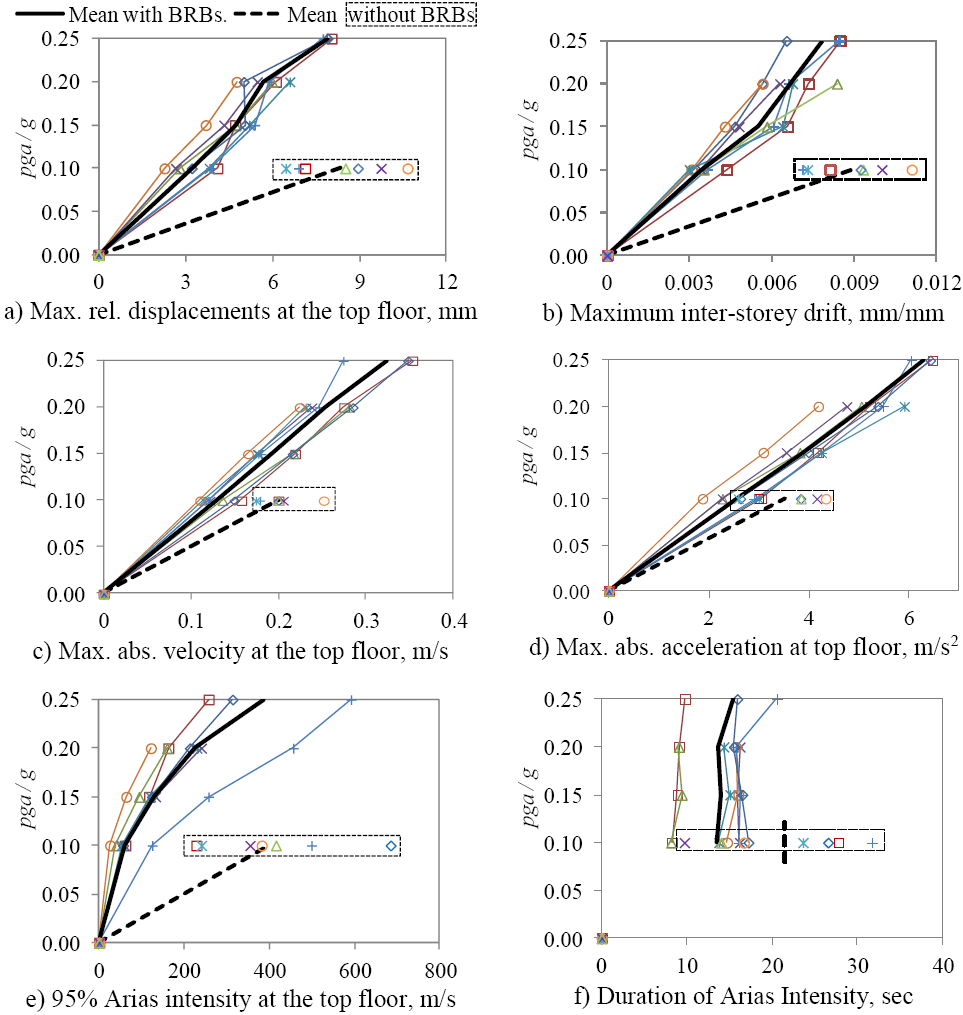
It can be observed, from Figure 14, that the inclusion of BRBs significantly reduced the responses. The mean of the maximum displacements, maximum inter-storey drifts and the Arias Intensity of the model equipped with BRBs and subjected to an intensity of pga= 0.25g, were smaller than that for the model without BRBs subjected to pga = 0.1g. For the floor velocities and floor accelerations, the model with BRBs can accommodate about 1.5 times more seismic intensity than the model without BRBs. In addition, by observing the dispersion of the data, it is appreciated that the model with BRBs is less sensitive to the seismic input than the bare model at the intensity level of pga=0.1g.
Finally, the duration of the intense phase (from 0.05Ia to 0.95Ia ), provided in Figure 14f, shows that the model fitted with BRBs had a much shorter duration of the intense phase. When the model was equipped with BRBs, the durations of the intense phases of the Arias intensities were almost constant for all four values of pga and the average duration was less than that on the bare model for pga = 0.10g.
Inelastic behaviour of the BRBs
This section is developed to determine the seismic intensity at which the BRBs reached inelastic behaviour, i.e. the seismic intensity at which the BRBs started dissipating energy by plastic deformation of their steel core.
First, the yielding inter-storey drift (θy ) is estimated and then compared to the maxima demands of Figure 14b. θy is defined by:
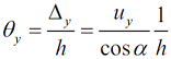 (2)
(2)
where Δ
y
is the relative displacement between two consecutive storeys at which yielding of the BRBs is expected, uy
is the BRBs axial deformation at which they yield,
By considering the connection ends of the BRBs used in the experiment as infinitively stiff, the yielding deformation of the BRBs can be estimated as:
 (3)
(3)
where Ly is the yielding length of the steel core of the BRBs, and fy and Es are the material’s yielding stress and modulus of elasticity - which were determined experimentally.
Substituting the values of Ly =330 mm (see Figure 3) and the experimental values of fy =405 MPa and Es =118,725 MPa. The yielding deformation of the BRBs is uy =1.12 mm. This is in agreement with the results of Figure 4 - where slightly nonlinear behaviour was appreciated for displacement deformation around 1 mm or below. Substituting uy =1.12 mm in equation (2) the yielding inter-storey drift in the first storey, where the maxima demands were observed, is:
By comparing θy = 0.005 with the inter-storey drift demands of Figure 14b, it can be observed that the BRBs presented linear-elastic behaviour for a seismic intensity of pga=0.10g, while inelastic behaviour started at an intensity of pga=0.15g.
Discussion
The measured results indicate that the model equipped with BRBs reduces the responses and their record-to-record variability (and hence, uncertainties). In addition, the Arias intensity (as a measure of the energy contents) showed that the model with BRBs may present significantly less damage than the model without BRBs.
Increases in damping were observed due to the inclusion of BRBs in the model. The damping increased from 0.3% to 7.6% for the first mass scenario and from 0.52% to 6.1% for the second mass scenario. However, it is difficult to quantify the contributions from the BRBs and from the connections between BRBs and the model. The observed increases of damping are significant and should be considered in the design process of structures equipped with BRBs. Depending on the design approach, namely force-based design (FBD) or displacement-based design (DBD), the level of damping provided by BRBs can be included straightforwardly. For example, in the FBD approach the increase of damping can be considered by modifying the design spectrum with a correction factor, such as that defined by equation (3.6) of Eurocode 8 (2004). In the DBD approach, the increased damping ratio can be considered directly in the estimation of the displacement demands, e.g. in equation (10) by Guerrero et al. (2016) the damping ratio provided by the BRBs (ξ 2) can be added to the damping ratio provided by the primary structure (ξ 1).
The permanent (or residual) deformations of the model equipped with BRBs were not possible to measure during the tests. But no permanent deformations were visually identified after each test and after all the BRBs were removed. This gives an indication of the low permanent deformation of the tested model. The costs associated with rehabilitation of structures equipped with BRBs may be reduced to replacing the devices without interruptions to the building functionality; which may be regarded as a cost-effective solution.
Since the responses of the model equipped with BRBs were significantly improved, it may be thought that these devices would benefit structures located in the lakebed zone of Mexico City. Including BRBs in new designs could lead to better performance or lower construction costs. Also existing buildings could be upgraded to achieve enhanced levels of performance.
Conclusions
Free vibration and shaking table tests have been carried out on a five-storey model and the results are summarised in this paper. The following conclusions have been reached:
The inclusion of BRBs in the model not only increased the stiffness but also the damping. For the first and second scenarios of mass, the increases were from ξ=0.3% to 7.6% and from ξ=0.52% to 6.10%, respectively.
All the response parameters (and record-to-record variability) were reduced for the model fitted with BRBs. Using the same pga=0.1g, the average values of the maximum displacement and maximum inter-storey drift were reduced by 58.5% and 62.2%, respectively. The maximum floor velocities and maximum floor accelerations were reduced by 35.4 % and 26.9 %, respectively. The Arias Intensity, as a measure of the energy content, was almost eight times less on the structure with BRBs than on the structure without BRBs.
These reductions suggest that structural and non-structural damage and losses of contents may be significantly less when BRBs are included in structures located in the lakebed zone of Mexico City.
From the tests with incremental seismic intensity, it can be concluded that the model fitted with BRBs was able to accommodate up to 2.5 times more seismic intensity in terms of lateral displacements, inter-storey drifts and Arias Intensity, and up to 1.5 times more seismic intensity in terms of floor velocity and floor acceleration.
Residual deformations of the model were not visually identifiable before or after all the BRBs were removed from it.

