


 nova página do texto(beta)
 Inglês (pdf)
 Artigo em XML
 Referências do artigo
 Enviar este artigo por email
 Citado por SciELO
  Similares em
SciELO
Similares em
SciELO 
 Permalink
1. Introduction
Microwave Photonics (MWPs) is an interdisciplinary area that studies the interaction of microwaves and optical signals; some of its main applications in microwave photonics systems include photonic generation, distribution, filtering, control, and processing of millimeter-wave signals [1].
There is currently great interest in having photonic wave-form generators, with a particular interest in radio-over-fiber (RoF) systems for current and future new generation internet networks, based mainly on electro-optics modulators of Lithium Niobate (LiNbO3) for its efficient operation at telecommunication wavelengths and the relative simplicity of manipulating its DC voltages and radio frequency (RF) signal parameters.
The generation of radio frequency (RF) waveforms is attractive due to different applications in communication systems, electronic equipment test measurements, modern radar systems, and optical communication systems; traditionally, these generators are based only on electronic technology [2].
However, generators based on photonic schemes have several advantages compared to purely electronic generators due to the process in the optical domain, such as greater bandwidth, high frequencies, low losses, and immunity to electromagnetic interference (EMI), low cost, and flexible frequency tunability [2,3,4].
Generation of the triangular waveform is the motivation of study due to its wide applications, and because it has a rising and falling linear edge in optical intensity, it has many advantages over any other waveform [5], such as optical signal conversion, optical frequency conversion, pulse compression, signal copying, and doubling of the optical signal [6].
The triangular waveform based on electro-optical modulators, they have been proposed with different structures such a Single-Drive Mach-Zehnder modulator (SD-MZM), Dual-Drive Mach-Zehnder modulator (DD-MZM), and the Dual Parallel Mach-Zehnder modulator (DPMZM), there are also proposals with two SDMZM modulators in a cascade [7,8]; however, this increases the complexity of the system.
Generators based on DPMZM [9,3] are among the most used due to their versatility to handle since they are composed of two MZMs in parallel in the same packaging; however, they are more complex and expensive.
Schemes based on eliminating frequency components with microwave photonics filters (MPF) such as [10] that use phase modulation (PM) have also been proposed and to obtain the notch filter, Bragg gratings in fiber optics and a Sagnac loop, resulting in a complicated scheme because it is dependent on polarization. A simpler one is proposed in Ref. [11] using an SDMZM generating triangular waveforms; however, it is necessary to adjust the phase of the RF signal accurately before being detected with a balanced photodetector.
Usually, the schemes mentioned above use mono-mode laser diodes (LD) as optical sources because of their excellent characteristics, such as low linewidth, high coherency, among others. Still, they are more expensive than low coherence optical sources. So, due to its minor cost, it is very convenient to implement waveform generators based on low coherence optical sources.
So, in this work, we propose a simple scheme to generate triangular waveforms based on an RF single sinusoidal signal and a low coherence optical source such as a superluminescent diode (SLD). We tuned a notch filter to eliminate even harmonic spectral components to get a triangle wave consisting just of odd-order harmonics. When we input the modulated SLD to our interferometer with the delay line, we obtain several undesired harmonics in addition to the required odd harmonic components. The band-reject filter formed by the interference of the carrier is tuned with the optical delay line (ODL) to reject the second spectral component, leaving the signal with odd components to obtain the triangular wave-form.
This paper proposes the generation of triangular wave-forms with pulse frequencies of 100, 150, 250, and 300 MHz instead of using higher frequencies of the order of GHz. We chose such frequencies motivated by a three-fold argument:
First, while telecommunications applications such as radio-over-fiber (RoF) or ultra-wide-band (UWB) signal generation use the GHz band extensively, our article focus on the RF band of hundreds of MHz due to their diverse applications in several fields such as RADAR, optical control of RF antennas, fiber-optic sensors, optoelectronic testing, and other instrumentation and signal processing applications. Second, our present research also consists of the proof-of-concept of the theory presented in this article. Our laboratory experimental capabilities cover this band of hundreds of MHz for our RF oscillators, photodetection/amplification/filtering subsystems, time/frequency analysis, and acquisition/signal processing equipment.
Third, while our present aim is limited to analysis and experimental proof-of-concept, the potential applications of these techniques in the field are promissory. We estimate that the initial developments in Mexico should begin in this RF band, where components and modules are presently commercially available.
Therefore, we generated triangular waveforms of 100, 150, 250, and 300 MHz, with a complete duty cycle by tuning the filter’s center frequency to the second harmonic frequency, with delay values of 2.5 ns, 5 ns, 1 ns, 7.5 ns, respectively.
2. Photonic filtering for radio frequency
Figure 1 shows the block diagram of a typical photonic filter for radiofrequency or microwave signals, composed of four blocks: the optical source, the electro-optical modulator, the photonic elements, and the photoreceiver. Photonic filtering has certain advantages over fully electronic ones, such as electromagnetic immunity, reconfigurability, tuning capacity, among others [12].
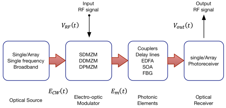
Figure 1. Block diagram of a typical photonic filter for RF signals. (SDMZM: Single-Drive Mach-Zehnder modulator; DD-MZM: Dual-Drive Mach-Zehnder modulator; DPMZM: Dual Parallel Mach-Zehnder modulator; EDFA: Erbium Doped Fiber Amplifier; SOA: Semiconductor Optical Amplifier; FBG: fiber Bragg grating).
In Fig. 1 an RF input signal V RF (t) modulates the continuous wave (CW) optical signal E CW (t). We can make the optical modulation through different architecture configurations using either a single frequency or broad-spectrum source. Such structures consist of an electro-optical modulator combined with photonic elements such as couplers, optical delay lines, fiber optic amplifiers, semiconductor optical amplifiers, etc. The resulting optical signal is detected to get an electrical RF signal V out(t) using the optical receiver.
The electric RF signal is V
RF
(t) = V
in cos(2π f
RF
t), where V
in indicates the amplitude and f
RF
the frequency of RF signal respectively. The
For this work, we implement the photonic filter using the configuration shown in Fig. 2. It consists of a broad-spectrum E CW (t) source, an electro-optical modulator with optical delays and couplers, and finally, a photoreceiver.

3. Photonic generation of triangular wave-form
As we know from Fourier analysis, a triangle wave only consists of odd-order harmonics (1). So, we must suppress any current even order harmonics using a photonic notch filter by tuning it to the delay line in our set-up.
The Fourier series for a triangular waveform is given by [13]:
Where DC is constant, ω is the fundamental angular frequency, and k is the harmonic of the series, where only odd harmonics are present and can be approximated by a finite number of components of the Fourier series.
Strictly speaking, the Fourier series of a triangular wave-form is infinite, but for practical applications, such wave may be obtained with only two harmonics [13] because the highest frequency harmonics are of minimal amplitude (change with 1/k 2) and do not have a significant contribution to the final waveform. Thus, the Fourier series can be simplified as:
Based on the block diagram of Fig. 2, we implemented the system shown in Fig. 3 to generate signals with a triangular waveform.
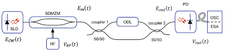
Figure 3 Schematic diagram of the triangular waveform generator (SLD: super-luminescent diode; SDMZM: electro-optical modulator; RF: local oscillator; ODL: optical delay line; PD: photodetector, OSC: oscilloscope, ESA: electric spectrum analyzer).
The optical carrier E CW (t) Eq. (3) consist of a super-luminescent diode (SLD) whose radiation is input into the electro-optical modulator (SDMZM) driven by a sinusoidal RF signal V RF (t) (local oscillator (LO), Eq. (4)).
We divide the optical signal E m (t) Eq. (5) using the 3 dB coupler-1, and then a variable delay line (ODL) is inserted on one arm of the coupler-1.
with m I = πν 0/V π being the modulation index, V π the half-wave voltage of Mach-Zehnder intensity modulator (MZIM) and θ = πV DC =V π , the relative phase between the two branches and V DC being the dc polarization voltage of MZIM respectively.
Both outputs of coupler-1 (E m (t - τ) and E m (t)) input to coupler-2 getting the signal E out(t), Eq. (6), τ ODL is the optical delay.
We use one of the outputs of coupler-2 to get an electrical wave i(t) Eq. (7), through photodetector (PD), where ℜ is the responsivity of PD and * indicates the complex conjugate.
For a constant value of θ the first two terms of Eq. (7) are constant corresponding at the DC term of Eq. (1) and as mentioned previously, to get the desired electrical triangular wave signal, we have to eliminate the undesired even spectral components that appear after photodetection.
Following Eq. (7) the dc terms,
The interference terms:
Therefore, the current:
For a given f RF , one chooses the interferometric delay τ in order to cancel the even spectral components.
4. Simulation
It is convenient to mention that we could not implement our scheme in the laboratory because we did not have a low coherence optical source. However, we did have a VPI Photonics Maker license, a widely recognized optical communications simulation tool. As our objective is to implement our scheme in the future in the laboratory, we use parameters of physical components (see Table I) to get results that will be useful for our experimental implementations.
Table I Technical specifications of the commercial components defined in the simulation.
| Component | Model and Specs |
|---|---|
| SLD | Exalos EXS1510, 3 dB-BW = 64 nm |
| SDMZM | RAMAR 202-PM15, BW = 1 GHz |
| ODL | Combining fiber optic and free space |
| PD | DET08CFC, BW = 5 GHz |
The diagram in Fig. 4 represents the blocks used in the simulator; the arrows in red are optical signals, and the blue ones are electrical signals. The signal selector will pass one frequency at a time with its corresponding delay to be detected and observed in the signal analyzers.
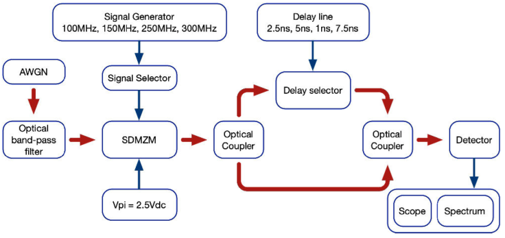
Figure 4 Simulation Schematic diagram, AWGN: Additive White Gaussian Noise generator, SDMZM: Single-Drive Mach-Zehnder Modulator.
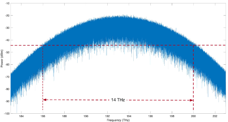
We modulate the optical source through the SDMZM with a sinusoidal signal of 100 MHz, 150 MHz, 250 MHz, and 300 MHz on the RF port with an amplitude of 1.2 V, and we set the half-wave voltage for the modulator at 2.5 Vdc. In addition, the delay values of 2.5 ns, 5 ns, 1 ns, 7.5 ns, respectively, are selected to eliminate the second harmonic generated from each frequency of the local oscillator. The low coherence optical source consists of a superluminescent light emitting diode (SLED) emitting in continuous wave (CW) and centered at 1553.6 nm with an amplified spontaneous emission spectrum as shown in Fig. 5 and 3 dB bandwidth of 64.5 nm.
5. Results
A 100 MHz sinusoidal signal is applied to the RF port, which, when passing through the proposed scheme and when detected, displays the waveform and its electrical spectrum as shown in Figs. 5a), b); in Fig. 5c), see the photonic filter with the delay line at 0.5 ns. The power ratio between the first and third harmonics is 19.4 dB, which is close to the theoretical value of 19.08 dB [14]; this difference is due to the bandwidth of the notch filter. We generate the triangular waveform by suppressing the second harmonic with the notch filter at 200 MHz as the center frequency and a 50 MHz bandwidth and a 40 dB extinction rate, as seen in Fig. 6f). When the local oscillator has a frequency of 150 MHz, the delay line is given a value of 5 ns; at 250 MHz, the delay is 1 ns, and at 300 MHz, the delay is 7.5 ns. With these delay values, the filter is placed to eliminate the second spectral component, that is, the component of 300 MHz, 500 MHz, and 600 MHz, respectively, to form the triangle wave, its spectrum, and the notch filter, as seen in Figs. 7d), e), f), Figs. 8d), e), f), and Figs. 9d), e), f) respectively.
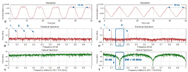
Figure 6 With LO at 100 MHz. [a) 100 MHz waveform, b) electrical spectrum, c) photonic filter], and 2.5 ns delay [d) triangle waveform 100 MHz, e) electrical spectrum and f) photonic filter].
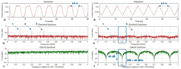
Figure 7 With LO at 150 MHz. [a) waveform, b) electrical spectrum, c) photonic filter], and with a delay of 5 ns [d) triangular waveform of 150 MHz, e) electrical spectrum, and f) photonic filter].
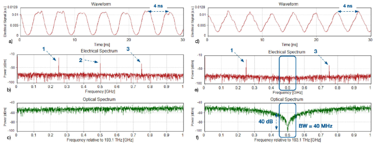
Figure 8 With LO at 250 MHz with a delay of 0.5 ns [a) waveform, b) electrical spectrum, c) photonic filter], and with a delay of 1 ns [d) triangular waveform of 250 MHz, e) electrical spectrum, and f) photonic filter].

6. Conclusion
We have demonstrated by simulation the implementation and characterization of a scheme for generating full duty cycle triangular waveform radio frequency signals. We base our system on using Microwave Photonics Filters (MPF) and a broad-spectrum optical source. Using this kind of source reduces the scheme elements required to get a more straightforward and cheaper system. Another advantage of our scheme is not performing multivariable adjustments to obtain the optimal triangular waveform. While other works reported the modulator control voltage and LO, amplitude needs to be adjusted precisely. In ours, we only change the delay value in ODL for tuning the center frequency of the notch filter and suppressing the signal’s second harmonic. We have thus obtained triangular waveforms with frequencies in 100 MHz, 150 MHz, 250 MHz, and 300 MHz using the appropriate rejection of the second component with a notch filter with a bandwidth of 40 MHz and a rejection rate of 40 dB. If we employ suitable optical delays, our technique can operate at much higher frequencies. However, the limitations are dominated mainly by the available RF oscillation frequencies and RF signal amplification and the frequency response of the photodetection/pre-amplification subsystems (up to the third harmonic at least). Other limitations concern noise-bandwidth trade-offs in the post-detection signals, real-time signal acquisition, and processing speed.

