


 nova página do texto(beta)
 Inglês (pdf)
 Artigo em XML
 Referências do artigo
 Enviar este artigo por email
 Citado por SciELO
  Similares em
SciELO
Similares em
SciELO 
 Permalink
1. Introduction
The effective-index guiding photonic crystal fibers (PCFs) are known to be single-mode within a wide wavelength range [1,2] due to wavelength dependent effective refractive index of the photonic crystal (PhC) cladding.
Recently, a great deal of attention has been paid to microstructured optical fibers (MOFs) possessing all-normal dispersion (ANDi) due to their abilities of reshaping the optical pulses and high-efficient supercontinuum generation. In particular, the papers [3,4] demonstrate efficient supercontinuum generation in large core ANDi PCF. However, in other works [3] ANDi-PCFs are claimed to form the parabolic pulses that are stable and can be generated with picojoulefemtosecond pulses. On the other hand, such fibers can be used to generate optical
pulses possessing the spectral properties of supercontinuum when excited by the femtosecond pulse at λ = 800 nm [3]. In the case of pulse-reshaping applications, the resulting spectrum is relatively narrow and does not exceed 1 µm. However, in case of supercontinuum generation, the spectrum is much wider and may spread, in some cases into midIR range. The confinement condition might not be met in this case since this ANDi-PCF possesses the core diameter of ≈ 1.5 µm and, therefore, it refers to as ultra-low core fiber. Due to the wide supercontinuum spectrum (which may achieve the order of 10 µm), large confinement losses may appear beyond certain wavelength of the order of the PhC pitch, which results in the loss of the fiber’s strong field localization property. In this paper, we refer to this wavelength as the fundamental mode cut-off wavelength or critical wavelength. The presence of the critical wavelength should be taken into account in theoretical modeling as well as in practical implementation when generating supercontinuum.
Although ultra-small core fibers have been investigated before [4], such fibers possess large diameter holes of d =0.96 µm while the pitch is α = 1 µm. In this case, the strong light localization within the core is achieved due to photonic band gap guiding rather than effective refractive index guiding. On the other hand, previous studies of endlessly single-mode PCFs based on the effective index guiding have revealed the conditions for the cut-off wavelength of a single-mode operation [4]. However, this study mentions nothing about the critical wavelength, which breaks the confinement condition of the fundamental mode of the PCF. In case of ultra-low core diameter, such condition may appear at wavelength of the order of the PhC pitch.
In this work, we determine the critical wavelength of the ultra-small core ANDi-PCF and investigate the field behavior beyond this wavelength by means of long-distance propagation simulation.
The paper is organized as follows. We first compare the dispersion of the ANDi-PCF obtained by two different numerical methods where the problem has appeared first. Then we analyze the field localization within the PCF core by means of the PWE method. After that, we find the fiber losses due to the mode leaking by means of the FDTD method. In the conclusions section we summarize the results obtained in this work.
2. Indirect evidence of the critical wavelength
The ANDi-PCF discussed in this work is the same as the one presented in paper [3]. The fiber refractive index profile represents the 2D hexagonal photonic crystal (PhC) made of fused silica with a missing central hole, which forms the fiber core. The PhC pitch is α = 1 µm, and holes radius r = 0.25α. The fiber core is surrounded by 7 rings of holes, which is supposed to be enough for strong field localization of the fundamental mode.
The dispersion of the PCF is usually found numerically by computing first the “dispersion characteristic” of the PhC, i.e., the mode eigen-frequencies relation on propagation constant ω(β), where β = n(λ) · k z , n(λ) is the material refractive index found from the Sellmeier equation [5] and k z is an off-plane wave vector. After this, the dispersion is computed using this well-known relation:
In Fig. 1 it is shown the dispersion computed using the finite elements method (FEM) as well as by the PWE method with different size of the unit cell.
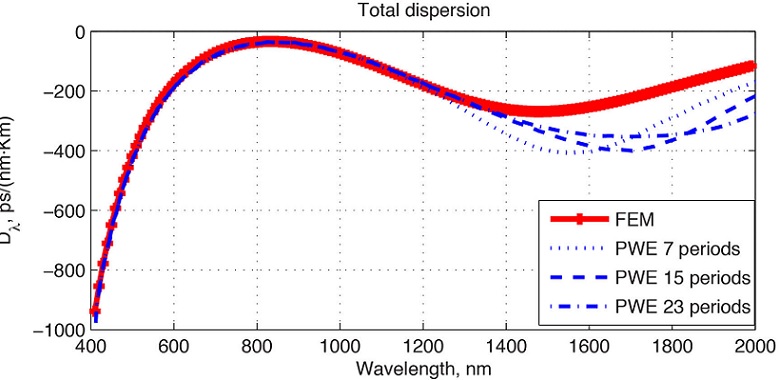
FIGURE 1 FEM results on the fiber dispersion (solid curve with markers) and the PWE ones for different size of the unit cell.
The characteristics coincide from 400 nm to ≈ 1200 nm and at longer wavelengths they possess significant differences reaching values up to 200 ps/nm·km. The reason for such difference has been easily found observing variations of the results obtained by means of PWE method. Namely, the PWE method can be used to find the eigen-frequencies of the PCF when the field is strongly localized within the core. Otherwise, the results do not have direct correlation with PCF field distribution [6]. Moreover, the eigen-frequencies obtained in such a manner would vary with the number of the PhC periods within the unit cell. Therefore, we conclude that after a certain wavelength the field is not localized within the core and form a leaky mode. This behavior is typical for the fiber when the wavelength is larger than the critical one for the fundamental mode.
3. PWE investigation of the field localization within the core
Using the PWE technique it is possible to synthesize the field distribution after the eigen-frequency is found [6]. The distributions computed within λ = 400 − 2200 nm are presented in Fig. 2.
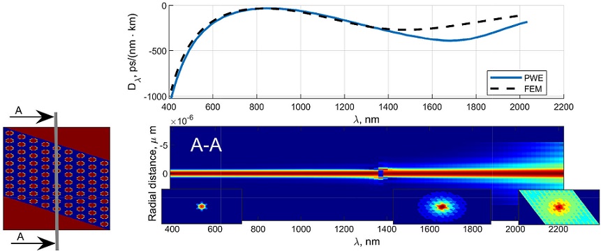
FIGURE 2 The fiber dispersion computed by the FEM and PWE methods, the unit cell (left) and mode field cut vs the wavelength. The core is formed by a single missing hole.
The figure consists of three parts. The first one (topmost) is a reference figure comparing the dispersion obtained by the FEM and the PWE methods. It is presented here for convenience of the analysis. In the left part it is presented the unit cell used in the PWE method to emulate the fiber. The vertical line crossing the unit cell demonstrates the direction of the field cut. The right bottom part with insertions demonstrates, namely, the field distribution along the cut AA plotted versus the wavelength. The insertions themselves represent the examples of the complete field distribution.
Namely, the main part of figure is the field cuts. It demonstrates that the field at low wavelengths (from 400 nm to ≈ 1350 nm) is strongly confined within the fiber core. In this range the dispersion computed by the PWE method is in complete agreement with the one obtained by FEM. However, if we analyze the field cut after, for example, 1600 nm it can be mentioned that the field is not confined within the core anymore. It penetrates into a PhC and the defects within the translated unit cells are no longer completely isolated one from another causing slight deviation of the dispersion. If we move to the longest investigated wavelength, the field here can hardly be called localized. It propagates inside the PhC cladding and, as we can see, spreads all over the unit cell, which makes the PWE method unsuitable to find the correct values of eigen-frequencies of the fiber in this particular case.
Such non-localized field distribution leads to a formation of a leaky mode and causes great fiber losses as will be demonstrated in the following section.
To prove that the non-guided modes are result of presence of critical wavelength and not based on the PhC properties, the same characteristics (as in Fig. 2) have been computed for the fiber with the same parameters but with a core with 7 missing holes. These results are presented in Fig. 3.
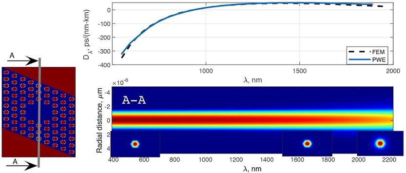
FIGURE 3 The fiber dispersion computed by the FEM and PWE methods, the unit cell (left) and mode field cut vs the wavelength. The PCF core is formed by 7 missing holes.
As we can easily see from the field distribution, in this case it is localized within the core region and, thus, demonstrating the correctness of dispersion computed by the method.
The proof can be also obtained by computing the effective refractive index of the fiber [6]. This argument is always present when describing infinitely single-mode PCFs [7] not taking into account actual core size.
Therefore, the PCF study by means of the PWE method field propagation along z-axis assuming the propagation conhas demonstrated the presence of the critical wavelength at stant β, the z-components of the electric and magnetic fields λ ≈ 1200 nm, which should be taken into account when are presented in form of harmonic functions as follows: computing the wide-spectrum supercontinuum generation.
4. Long distance propagation study
Unlike the PWE method, the FDTD technique allows for the study of field propagation along the fiber. This gives the possibility to find the fiber losses in case of mode leaking pre- In this case, z-derivatives are found analytically. The dicted by the PWE method. computation region in this case becomes two-dimensional.
In our work, we have implemented the FDTD with nonsplit field perfectly-matched layer (PML) [8]. To emulate the field propagation along z-axis assuming the propagation constant β, the z-components of the electric and magnetic fields are presented in form of harmonic functions as follows:
In this case, z-derivatives are found analytically. The computation region in this case becomes two-dimensional. The recurrent equations for one of electric andmagnetic components are then presented in following form according to [8]:
Here the spatial step is the same in both directions Δ = Δx = Δy. The value of β' stands for β⋅Δ. The permittivity ε defines the PCF transverse profile. The κ and σ define the artificial losses at the PML regions.
The time step is selected according to Courant condition as follows:
The method has been implemented using the CUDAGPU [10], which allowed simulating the field propagation through the fiber over several centimeters within several minutes. This should be enough to estimate the losses.
In Fig. 4 it is presented the field intensity in the center of the PCF while propagating along the fiber. Long-period beatings are the result of the interference of orthogonal polarization modes. Since we use the Gaussian beam profile as the initial field distribution, it takes about 1 mm for the PML to absorb the radiation leaking from the core. Due to this, slight irregularities are observed close to 0 cm propagation distance.
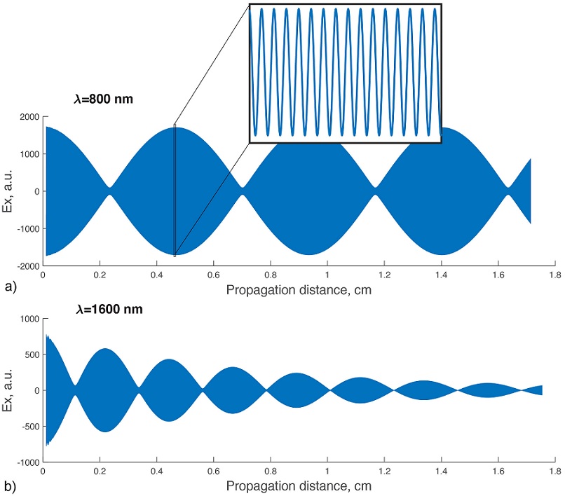
FIGURE 4 Ex component of the propagating field in the center of the fiber core at 800 nm a) and 1600 nm. b) The insertion at the top is enlarged field after ≈ 4 mm of propagation.
The field at λ = 800 nm does not demonstrate any visible changes of the amplitude while in case of λ = 1600 nm the amplitude possesses rapid exponential decay as is seen in Fig. 4b. This fact unambiguously points to inability of the fiber to guide any mode inside the core.
The analysis of the field amplitude decay allows to determine the losses by simple approximation of the field intensity envelope with an exponential function. An example of such approximation as well as the loss spectrum of the PCF are shown in the Fig. 5.
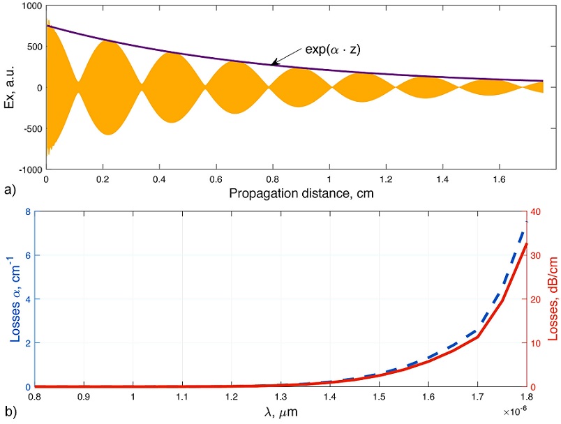
FIGURE 5 Ex component of the propagating field in the center of the core at 1600 nm with an envelope a) and the losses presented both in [cm-1] and in [dB/cm].
It is clearly seen that even after λ ≈ 1200 nm the losses become huge (of the order of several dB/cm) and the field vanishes completely after several millimeters. These effect cannot be neglected when computing the pulse propagation, which rely on the fiber guiding properties.
5. Losses reduction in the ANDi-PCF
As it has been demonstrated with the PWE method, the major problem when encountering the critical wavelength is weak field confinement, which causes high losses. Although it is impossible to eliminate the losses completely it is possible to reduce them to reasonable values by increasing the number of PhC rings in the cladding.
In Table I, it is presented the PCF losses in some specific cases and in Fig. 6 it is shown the exponential decay of the losses with growing number of rings of holes. Except for the number of the rings, the other parameters stay unchanged and are the same as described in Sec. 2. The core in this case is formed by a single missing hole in the center.
TABLE I The losses (in[cm-1]) of the ANDi-PCF at the wavelengths beyond the fundamental mode cut-off.
| Rings λ; nm | 1200 | 1600 | 2000 |
| 6 | 1.61 · 10-3 | 3.76 · 10-1 | 16.6 |
| 7 | 1.45 · 10-4 | 1.12 · 10-1 | 2.72 |
| 8 | 4.07 · 10-5 | 3.43 · 10-2 | 1.44 |
| 9 | 2.69 · 10-5 | 1.1 · 10-2 | 0.81 |
| 10 | 1.3 · 10-5 | 3.31 · 10-3 | 0.47 |
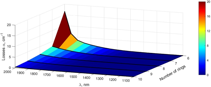
Analyzing the figure we conclude that even if the number of rings becomes large the losses are always present at higher wavelength. The exponential-like decay of the losses with growing number of rings gives a possibility to suppress them to any required value at short distances. However, the technological expenses in this case would be unnecessarily high.
6. Conclusions
In the paper we have demonstrated the dramatic growth of the losses of ANDi-PCF with 7-ring cladding, starting at approximately 1200 nm. It has also been demonstrated that the losses beyond the critical wavelength are the result of low PCF core diameter rather than the cladding PhC geometry.
Losses estimation has demonstrated that the radiation with λ ≥ 1200 nm will dissipate from the fiber after several millimeters (with losses up to 10 dB/cm). Although at the wavelength of 800 nm the field is well-confined, the fiber with such parameters cannot be used for a wide-spectrum supercontinuum generation as well as for other applications involving frequency conversion into a long-wavelength range due to losses at higher wavelengths.
Even though the critical wavelength only depends on the cladding properties, the losses due to the low core size strongly depend on the number of rings of holes forming the cladding. In specific applications where short lengths of fiber are used, the losses beyond the critical wavelength may be significantly reduced by using a wider cladding.

