


 nova página do texto(beta)
 Inglês (pdf)
 Artigo em XML
 Referências do artigo
 Enviar este artigo por email
 Citado por SciELO
  Similares em
SciELO
Similares em
SciELO 
 Permalink
1. Introduction
Optical fiber sensors have distinctive advantages compared with conventional standard sensors, such as immunity to electromagnetic fields, non-electrical conductivity, passive measurements, fast response, small size, low weight, and compatibility with optical fiber technology [1]. Optical fiber sensors have been used to measure a high number of physical, chemical, and biological parameters.
Several optical fiber devices have been proposed and used for the measurement of wide physical parameters. Regarding the physical parameter of displacement optical fiber sensors, several works have been reported. For instance, it can be mentioned the based on Mach-Zehnder interferometer [2], multi-mode interference [3,4], Bragg gratings [5-7], Fabry-Perot interferometer [8,9], intensity modulation technique [1, 10], bundle displacement [11], bending with plastic fiber [12], multimode fiber coupler [13]. However, most of them have experimental setups in free-space [3,9-11,13] or have no-simple constructions that can obstruct the sensor functionality. For instance, some need a transducer to sense the physical parameter to quantify [1, 2, 4, 12]; others have a limited dynamic range, especially the ones based in Fiber Bragg gratings [5-7]. Since most of the FBG works, the displacement is related to the stress over the grating. If this stress force is exceeded, the fiber grating can break, or also the grating can be fractured by fatigue caused by cycling mechanical strain, which shorted the useful sensor operation time. One of the most utilized structures to sense physical parameters is the Fabry-Perot Interferometer (FPI), which has been widely used as a sensing device. The FPI structure devices are significantly sensitive to external perturbations. Consequently, it is possible to use this sensitivity characteristic to use the FPI structure for various applications. Its wide sensing applications include the sense of angle [14], humidity [15], strain [16,17], temperature [18], refractive index and thermo-optic coefficient [19], pressure [20], and also the related parameter concerning to this work, displacement [8, 9, 21]. However, most reported displacement sensing works based on FabryPerot interferometers have a gap in the free space. This freespace gap is a disadvantage characteristic that can add dust contamination to dismiss the sensor performance and include cleaning maintenance routines for the well functioning of the sensor or can limit the sensor operation to controlled environmental conditions such as in a laboratory. Also, some of them need metal film deposition to improve the reflections of light.
A particular similar method for displacement sensing is reported by Kent A. Murphy et al. [8]; it is based on quadrature phase-shifted, the interrogation method is done by the phase change generated between reflected beams by the fiber ends. In this case, the intensity changes caused by varying the gap separation have a sinusoidal shape due to the use of one wavelength, which reduces performance capability to the sensor measurements limiting the amount of data, which might be if a wide-band wavelength is utilized. Also, the reflection scheme is composed of a non-reduced number of elements. It has two capillary glass (hollow-core fiber), two tapered couplers, four inserted fibers in the hollow core fibers, two laser diodes, and two detectors, which can add distortion to the sensor signal due to the long path that the signal has to travel through all the components.
This work reports a novel in-fiber optical FPI mode interferometer and its applications for absolute displacement sensing. It can be interrogated by measuring the free spectral range using the Fast Fourier Transform (FFT) of the transmitted sensor spectrum. Additionally, the insertion loss of the transmitted sensor spectrum, which shows a linear dependence on the gap separation distance, can be used for sensor interrogation. The proposed device, together with the experimental transmission setup, consists of a reduced number of elements. These minimal elements make a simple construction and operation that generate a wide-wavelength range data analysis and augment its precision due to the reduced errors that many parts may induce.
2. Sensing structure and its working principle
The sensing device consists of two well planes cleaved tips of standard optical fiber (SMF) inside a capillary glass with an inner diameter of ∼ 126 µm and outer diameter of ∼ 140 µm. As the standard SMFs have a diameter of 125 µm, the inner diameter of the capillary glass was fabricated to be approximately 126 um as a tolerance to fit the standard optical fibers inside the capillary glass. One tip was fused to the capillary by applying an electric arc from a standard splicing machine. In contrast, the other tip was not adhered to the capillary to be free to move longitudinally. Figure 1a) illustrates an isometric drawing of the structure device. The light behavior when light propagates through the structure is shown in Fig. 1b). This light behavior is the main functioning mechanism and is based on the interference of two beams, which are out of phase [22]. First, the intensity of the fundamental mode of the core fiber (I 0) is propagated via the input SMF until it reaches the first SMF plane tip. Then, it is propagated through the air until it reaches the second SMF tip. Part of this intensity is coupled to the output SMF (I 1), and the other part of the power is reflected. The reflected power to the air is reflected again by the first SMF tip to the second SMF tip, where it is coupled into the output SMF (I 2). As the beams I 1 and I 2 propagate different distances, they have a phase difference, generating interference between the two intensity beams.
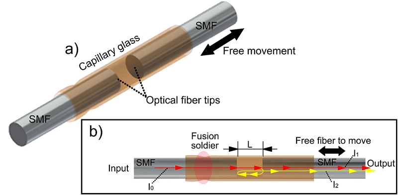
FIGURE 1 Drawing representation of the proposed optical fiber Fabry-Perot mode interferometer for displacement sensor. a) Isometric drawing of the structure and b) illustration of the light beam propagation through the device structure.
It is important to remark that back reflections in the proposed structure may damage the optical source, including noise or instability to the sensor signal. However, in the presented experiments in this work, it was used a superluminescent diode with an optical power of around 0.85 mW @ 500 mA of supply current, as the level intensity is not high in this work, none of these disadvantages were presented. Also, the device can be used with higher power sources so that the power can be increased without affecting the devise performance until the reflections back to the source do not become high enough to damage the same source. On the same hand, when back reflections start to generate problems to the sensor performance for higher optical powers, the back reflections can be eliminated by including an optical isolator or an optical circulator in the sensor structure, avoiding the undesirable reflections and keep the source safe. Moreover, the power will be limited to the maximum power that the optical isolator or the optical circulator can support.
Accordingly, with the difference in optical paths of the two beams into the structure of the Fabry-Perot interferometer, the intensity transmitted by the interferometer is governed by the following expression [23]:
Where I 1 and I 2 are the intensity of the two beams that are coupled to the output SMF, L is the gap length between SMF tips, λ is the operation wavelength, n is the refractive index of the air gap, and φ 0 is the initial phase difference. The cosine term adds a periodicity to the output intensity with a dependence on L, λ, and φ 0.
Another essential parameter related to this work is the fringe separation, Free Spectral Range (FSR), in the spectral interference pattern of the output spectrum at the output SMF. The spectral space between two peaks of the interference spectrum happens when:
Where λ 1 and λ 2 are the corresponding wavelengths of the maximum intensity fringe value. From Eq. (2), it is easy to obtain:
Since the FSR has a dependence on the gap separation between tip fibers, a change in this length can be quantified by the FSR value. As a consequence of increasing the gap length of the structure device, less light is coupled to the output fiber (this effect is the responsibility of the functioning of the displacement sensors based on bundle fibers due to the divergence effect). It is allowed an increase in the insertion losses of the device. As a result, an increase in the gap length separation can also be quantified by the insertion losses of the proposed device.
3. Experimental results
A simple transmission setup was used to characterize the device. As a light source, a superluminescent diode centered at λ 0 = 1550 nm was used, and the detection was carried out by an optical spectrum analyzer (OSA), as it is illustrated in Fig. 2.
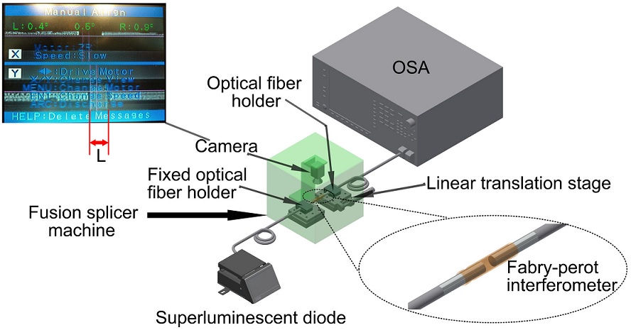
An optical fiber fusion splicer machine was used to vary the separation gap distance of the interferometer structure. The input SMF and the output fibers were mounted in the fiber holders of the splicer machine. The input fiber is remained fixed, whereas the output SMF is linearly displaced, so by linearly displace the input holder fiber stage, the gap separation between SMF tips is changed. The camera of the splicer machine was used to measure the separation between SMF tips by image process (see Fig. 2). As in the experimental tests, the ends of the device were mounted in the fiber holders of an optical fiber splicing machine; the structure device is limited to avoid bending and torsion that may cause the device to break. Consequently, for in situ applications, the device must be mounted similarly with holders to avoid breaking and ensure its good performance.
As discussed in Sec. 2, a change in the gap separation SMF tips will be reflected in an FSR change. Figure 3 shows the dependence of the period (FSR) on the gap separation between SMF tips. Also, the inset in Fig. 3 illustrates the spectrum transmission of the interferometer for 49.63, 126.81, and 212.79 µm SMF tip separations, as can be noticed from this inset on Fig. 3, by changing the gap separation, not only the period (FSR) is affected, but the insertion losses are also altered, which decreases when the separation increases.
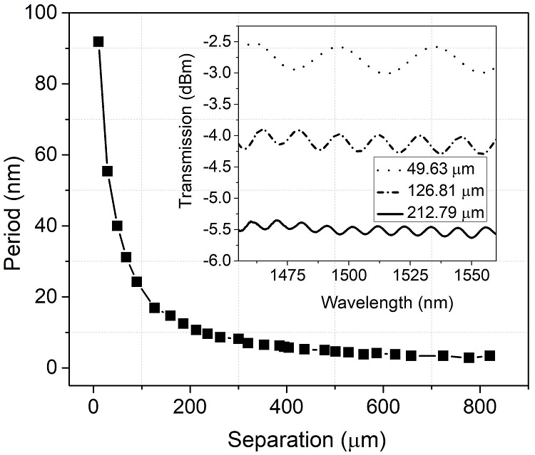
FIGURE 3 Displacement versus the period of the optical fiber Fabry-Perot interferometer, inset is the spectrum transmission for Fabry-Perrot interferometer separations of ∼49.63, ∼126.81, and ∼212.79 µm.
The use of the FFT is very useful in data analysis to find spatial frequencies of signals [24,25]. In this work, the FFT is used to evaluate the spatial frequency of the interferometer, then the corresponding FSR, and finally, the separation distance between SMF ends of the interferometer structure. Figure 4 shows the FFT in the spatial frequency (nm−1) for the interferometer spectra for separation distances of ∼ 49.63, ∼ 126.81, and ∼ 212.79 µm, which peaks in curves illustrated to have spatial frequencies of 0.029, 0.070, and 0.111 nm−1 for each separation distance. From this Fig. 4 (spatial frequency vs. power), it can be noticed that the spatial frequency increases as the separation between tips of optical fiber increase as it was expected from inset in Fig. 3 and Eq. (3). In Fig. 5 it is illustrated the Fast Fourier Transform as a function of period for the same separation distances for Fig. 4, it is ∼ 49.63, ∼ 126.81, and ∼ 212.79 µm. It can be seen that the period decreases as the separation increases, as it is predictable since the period is inversely proportional to the spatial frequency. Now, the period for every separation distance is designed by the peaks curves of 11.37, 17.02, and 42.56 nm, which that values corresponds to separation distances of 212.79, 126.81, and 49.63 nm from Fig. 3.
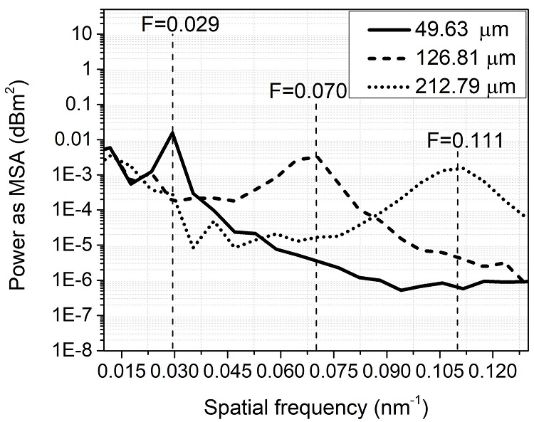
FIGURE 4 Spatial frequency versus power as MSA of the Fast Fourier Transform of the interferometer spectrum transmission for separation distances of ∼ 212.79, 126.81, and 49.63 µm, corresponding to frequencies of 0.029, 0.070, and 0.111 1/nm, respectively.
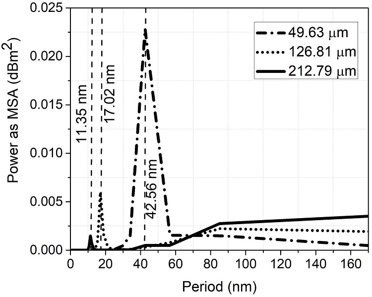
FIGURE 5 Fast Fourier Transform of the interferometer spectrum transmission for periods of 11.37, 17.02, and 42.56 nm, corresponding to the separation distances of ∼ 212.79, 126.81, and 49.63 µm, respectively in Fig. 3.
Additionally, it is noted that the insertion losses of the interferometer increase as the separation increases. This increase in losses is caused to the divergence of light that produces more and more light to escape when divergence increases by a separation increase, making an increase of lost light that can be seen as an increase of insertion loss of the interferometer. Figure 6a) illustrates the intensity versus gap separation distance at a wavelength of 1550 nm. Figure 6b) shows the spectral transmission of the proposed device for several distances ranging from 0 to 820.56 µm. There is an intensity dependence on the separation distance. The device exhibits an approximate linear behavior as the separation distance changes with a sensitivity factor of -0.033 dBm/µm. As all the intensity light for all the used range of wavelengths (1480 to 1640 nm) in the spectrum transmission have a similar dependence on the separation between fiber tips, the wavelength interrogation can be realized with any wavelength photo-detector ranged from 1480 to 1640 nm.
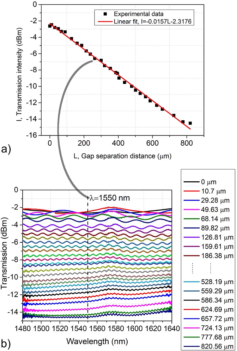
FIGURE 6 Intensity dependence on the gap separation distance. a) Intensity at 1550 nm for the same range of distances, a linear fit of the data is included in this graph, and b) spectrum transmission for L separation distances from 0 to 820 µm.
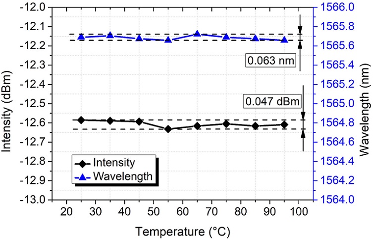
Another critical aspect that needs to be considered over the sensor performance is the temperature effect on the interferometer device. In order to explore this effect, the interferometer with a random separation distance was positioned on a hotplate. The temperature was increased from 25 to 95◦C with 10◦C of step. The intensity and wavelength of a notch in the interfering spectrum were recorded to every temperature value. The results of these recordings are shown in Fig. 7. It was observed that maximum variations of 0.063 nm and 0.047 dBm were found for wavelength and intensity. These variations may be due to refractive index changes by the thermo-optic effect and dilatation in the glass material caused for the temperature variations. However, to do not induce measurement errors by temperature changes, those effects can be removed over the sensor performance by maintaining the temperature constant.
4. Conclusion
An in-fiber Fabry-Perot interferometer for displacement sensing applications based on a microcapillary glass as a fiber guide is demonstrated. The Fabry-Perot interferometer is constructed just from the Fresnel reflections at two aligned planar SMF ends. The two SMF ends are forced to be aligned by introducing them in a microcapillary glass. One fiber end is fixed inside the capillary glass by fusing it with an arc discharge from an optical fiber fusion splicer machine. The other end fiber was free to displace linearly inside the capillary glass. The manufacturing process of the proposed device is made up only of an electrical discharge from the splicer machine and the insertion of two optical well cleaved optical fibers into a capillary glass. The functioning of the proposed device is simple without involving many optical fiber devices, which adds speed and simplicity of performance. The operation of the device is based on the movement of the free SMF end tip. As the free SMF end is moved, the separation between reflecting interfaces is modified, which generated an FSR change and an intensity variation. In FSR change, the FFT can be used to find the spatial frequency and period (FSR), which provides the information to obtain the length that the fiber tips have in separation. As not only is the FSR modified when the separation between SMF ends, but also the insertion losses. The sensor interrogation for this proposed device can be realized not only by period variations of the transmission spectrum but also by intensity variations as a second alternative method since by measuring the intensity of the transmitted spectrum at a particular wavelength (of a wide range of wavelengths) could be determined the separation distance between the optical fiber tips. Consequently, a straightforward approach, simple, easy to manufacture, possible double interrogation method, and suitable displacement sensing device is proposed. The device can be easily used and incorporated for measuring displacements lengths associated with deformations for applications in health monitoring on mechanical structures, fault diagnosis, stress fatigue in mechanisms, and structural deformations, to mention some of the most important.

