


 nova página do texto(beta)
 Inglês (pdf)
 Artigo em XML
 Referências do artigo
 Enviar este artigo por email
 Citado por SciELO
  Similares em
SciELO
Similares em
SciELO 
 Permalink
1. Introduction
Surface hardening opens the possibility of developing materials with desired properties to solve engineering problems. This technique has been used mainly to improve material hardness. Although there exists a great demand in the improvement on machine elements, it is also of enormous importance to improve industrial processes of the machine materials to corrosion and wear. In this regard, several thermochemical treatments have been proposed to enhance the mechanical properties of material surfaces subject to wear and corrosion. The improved hardness has been obtained by coating the metal using processes such as boriding [1-4]. In recent years, other alternatives such as the duplex coating [5,6], and more particularly the combined surface hardening with boron and carbon [6,7], appeared to be an excellent option for surface hardening. This process takes advantage of mass transfer phenomenon (diffusion) which cause the distribution of boron and carbon atoms in the material to change the chemical composition on the surface. The, processed metal surface increases its mechanical properties as hardness. Although this resulting property is often attractive, no studies based on the evaluation of corrosion resistance have been published in the literature. In this sense, the aim of this work is to evaluate the surface corrosion resistance of the ASTM A-36 steel by depositing a boron-carbon coating via boriding. Followed by carburizing technique. For this purpose, different characterization techniques were used to evaluate the hardness, microstructure, morphology, X-ray diffraction and corrosion properties of the boron-carbon layer on ASTM A-36 steel. Additionally, the evaluation of corrosion on samples was conducted by using a homemade 3Dprinted electrochemical cell.
2. Experimental procedure
25.4 mm Dia.×5 mm long ASTM A-36 steel, with chemical composition of 0.2 % Cu, 0.26 % C, 0.05 % S, 0.75 % Mn and 0.04 % P, was used as substrate. For sample B, the boriding process involved deposition of boron paste (consisting of 5 wt.% B4C powder, 5 wt.% KBF4 as a flux and 90 wt.% SiC as refractory material) on the steel substrate to form a layer of about 5 mm thick. The coated steel sample was then situated in a preheated muffle furnace at 950oC for 4 h. For sample BC, boriding was followed by the carbonizing process. The carbonizing treatment was conducted via the pack cementation method in a muffle furnace at 930oC for 6 h using charcoal powder. The cross-sectional view of the samples was observed by optical microscopy. Where the samples were processed by conventional metallographic and etching by using nital 3.5. To perform the hardness test, the ASTM E384 standard was used, and a load of 0.981 N was applied for 15 s. Diffractograms were made using monochromatic radiation CuKα line (wavelength 1.5406 Å) controlled at 35 kV and 15 mA by Grazing incidence small angle X-ray scattering (GISAXS). The corrosion analysis was done by using EIS and Tafel technique, employing a novel 3D-printed electrochemical cell from a commercially available composite of polylactic acid (PLA). Tafel and EIS test were carried out using 3.5 wt.% NaCl solution in the electrochemical cell at room temperature. An open corrosion potential was applied during 60 min. A sinusoidal alternating current signal of 10 mV and a sweep frequency from 1 MHz to 50 mHz were used for the EIS test. The Tafel polarization plots were obtained by performing a scan comprising ± 250 mV vs. corrosion potential (Ecorr) at a scanning speed of 0.5 mV/s. Tafel curves were fitted to find both Icorr (corrosion current) and Ecorr. Further, the corrosion current was calculated from Icorr according to ASTM G102−89 standard. A minimum of 3 samples for each experiment were exposed to the tests and compared with untreated ASTM A-36 steel (sample V).
3. Results and discussion
The hardness of the ASTM A-36 steel before heat treatments (sample V) was about 162 HV. After the boride process, the surface hardness of sample B was about 960 HV, whereas that of the sample BC was about 164 HV, similar to virgin sample.
The optical cross-sectional images of samples B and BC are shown in Fig. 1. The Optical microscopy analysis of the samples with the same cross-sectional area shows that boride coating composed on the surface of steels has a shark tooth morphology and a boride layer with a thickness of about 60 µm in both samples. Figure 1a) shows that the boride phase, obtained from the boriding process, on the surface of sample B is Fe2B [4]. The carburizing after boriding promotes the formation of coatings on the outermost layer of the samples with a thickness of about 17 µm over the boride layer (Fig. 1b)).

Metallographic analysis of the BC sample is shown in Fig. 2. It is well known that in a hypoeutectoid steel the equlibrium microstructure at room temperature consists of ferrite and pearlite [8], so that, as the hardness of the outer layer of the BC sample is similar to sample V, it suggests that the outer layer is composed as a virgin sample, instead of Fe3C as mentioned by Lopez-Perrusquia et al. [9]. In this sense, Bhadeshia et al. [10] revealed a microhardness of about 1230 HV in cementite, while Lopez-Perrusquia et al. [9] reported a hardness for cementite similar to an untreated sample as reported in this work. It suggests that his analysis may was not properly done.

The inner boride layer, shown in Fig. 2, was formed before the carburizing process and then it was displaced inwards by the carburizing treatment. The outer layer represents the dissolved carbon in the austenite during carburizing process. During this process, the carbon atoms diffuse through the boride layer to form austenite displacing the boron atoms, which at the same time diffuse depper into the material. Finally, it forms an outer layer of ferrite + pearlite, since it exhibits a similar hardness than sample V.
Figure 3 shows the X-ray diffraction patterns of samples B and BC. According to the 361332 card from ICDD’s Powder Diffraction Files, the diffraction peak positions confirm that iron diboride (Fe2B) phase on boride and borocarburized ASTM A-36 steel sample was all formed. Non-indexed peaks on diffractograms may correspond to noise, rust, or residues from the hardening process as shown in others works [11,12].
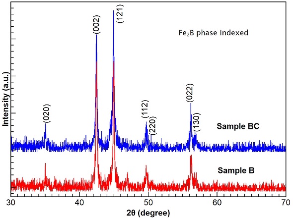
The X-ray diffraction spectrum corroborates that the boride phase on layer is formed of Fe2B for both samples because there is a full compliance to the diffraction peak positions and the diffraction database. An important fact is that X-ray diffraction patterns are clearly related with the tetragonal iron diboride phase which has lower brittlement than the secondary crystalline FeB phase. However, the proper identification of the outer layer in sample BC was not possible as its diffraction signal is not enough or it is inside the diffraction noise, and more work is needed.
The corrosion study was achieved by using our own 3D-printed electrochemical cell, Fig. 4. The manufactured cell has a size of 100 mm length, 50 mm width and 50 mm height. The container has a volume of about 100 ml that held the electrolyte solution, allowing to place 1 cm2 area of sample (WE). 3D printing allows to adapt the design of an electrode at the lowest possible price. As the counter electrode, a platinum foil of 0.1 mm thickness and 99.9 % wt. purity, so reducing its price, was used. A commercial Ag/AgCl reference electrode was employed to evaluate the electrode potentials. Virgin polytetrafluoroethylene (PTFE) gasket was used between the electrolyte solution and the working electrode to seal the cell. The first reported applications of fused deposition melting (FDM) in the electrochemical research include cells for spectro-electrochemistry [13], building reaction cells for water electrolysis [14], as well as the construction of electrochemical flow cells [15, 16], 3D printed electrodes [17], electrochemical cells to sensors [18], reference electrodes [19]. However the manufacture of an electrochemical cell serving as galvanic cell for materials has not been reported. It is important to mention that 3D printing allows the production of flexible and complex electrochemical cell designs which can be profiled, sized and potentially realized in a single, easy process, reducing materials, costs and work. Additionally, 3D printing allows the use of other thermoplastic filaments. It is important to remark that a complete work about this cell is in process.
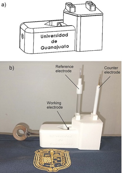
Figure 4 a) CAD model assembly for the electrochemical cell. b) Complete electrochemical design fabricated via 3D printing using polylactic acid (PLA) plastic.
In this sense, Fig. 5 shows the electrochemical impedance (EIS) and Tafel polarization spectra obtained during the testing of samples V, B, and BC in NaCl aqueous solution.
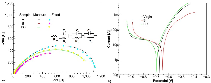
Figure 5 a) EIS and b) polarization plots for samples V, B and BC in NaCl 3.5 %wt. solution. The inset represents the suggested equivalent circuit, Rsol(C1R1)(C2R2)(C3R3) on ASTM A-36 steel sample.
As can be clearly seen from Fig. 5a), projection of the boride sample impedance (x−axis) is similar than the borocarburized steel and higher than boride sample. As a first approximation, these results suggest that the boriding process over the steel provides a lower corrosion resistance than the virgin ASTM A-36 steel.
The inset in Fig. 5a) shows the improved equivalent electrical circuit for the samples. The model aimed to simulate the chemical behavior of the steel surface in the presence of Cl− ions. Rsol corresponds to the solution resistance and (C1R1)(C2R2)(C3R3) to the resistance and capacitance of the substrates. The data fits with the equivalent electrical circuit is presented in Table I with a low relative standard error (RSE < 10 %).
Table I Parameters of proposed equivalent electric circuit.
| Parameter | Sample V | Sample B | Sample BC |
|---|---|---|---|
| Rsol (Ω) | 12.3 | 11.7 | 11.3 |
| C1 (μF) | 175.7 | 741.3 | 370.1 |
| R1 (Ω) | 13.0 | 12.8 | 11.5 |
| C2 (μF) | 263.4 | 1811.0 | 603.3 |
| R2 (Ω) | 135.2 | 85.4 | 129.6 |
| C3 (μF) | 366.6 | 3349.0 | 888.1 |
| R3 (Ω) | 960.2 | 671.4 | 845.8 |
| RP (Ω) | 1108.4 | 769.6 | 986.9 |
The amount of resistances (R1, R2, and R3) represents the polarization resistance, Rp , of the sample. A higher value of Rp implies a better corrosion protection capability of the layer. It is important to note that for all the samples, Rsol was very similar due the same solution was used. Table I shows a greater charge transfer resistance of 1120.7 Ω for sample V while samples B and BC have resistance equal to 781.3 Ω and 998.2 Ω, respectively. These results show that the boride sample has less resistance to corrosion than the untreated sample; however, its resistance increases after undergoing the carbonizing process to form the outer layer, as shown in Fig. 3.
Also, Fig. 5b) shows the Tafel polarization behavior where sample B and BC exhibits less negative corrosion potential related to sample V. Samples with more negative potential, Ecorr, can have some extra protection, acting as cathodic protection. In this case, the substrate, with a more negative potential, works as a sacrificial anode [20]. The values of corrosion potential (Ecorr) and corrosion current (Icorr) obtained from the Tafel polarization curves are shown in Table II. These values shows that the charge exchange activity, (Icorr), at the interface of the samples exposed to the boride process is higher than the virgin sample. This is manifested as an increment in the corrosion current, Icorr. On the contrary, the sample BC shows a close corrosion current as the virgin sample, suggesting that the material of the outer layer is like the substrate. Thus, it could be partly inferred that during the boriding kinetics of our samples, resistance to corrosion decreases, and it increases after carburizing process because the outer layer is similar than substrate. It should be pointed out that the formation of this outer layer due to the boron-carbon coating process opens the possibility of modifying it through other techniques such as burnishing [21-23], heat treatment, etc., which could improve both its hardness and corrosion resistance.
Table II Values of corrosion current (Icorr) and corrosion potential (Ecorr).
| Values | Sample V | Sample B | Sample BC |
|---|---|---|---|
| Ecorr (mV) | -673.7 | -648.0 | -694.6 |
| Icorr (μA) | 12.2 | 26.0 | 13.3 |
When untreated ASTM A-36 steel is exposed to corrosion, aggressive Cl− ions cause corrosion on the steel. Consequently, Fe+2 ions are formed, and then react with OH− ions producing rust [24]. Although, Fe2B phase is a ceramic material with a high hardness [25] and high corrosion resistance [26]. It protects any surface against the attack of aggressive ions as Cl− ions, which are responsible for the steel corrosion. However, Fig. 5 shows that boride layer produces a lower corrosion resistance in the material. Despite some works [27,28] reported that Cl− ions could penetrate through the cracks in the boride coating causing corrosion on substrate, Fig. 6 shows some saw tooth needles from substrate crossing the boride layer that reduce the corrosion protection of the boride layer by exposing the substrate directly to the electrolyte solution. Additionally, Fig. 5 shows how the corrosion potential (Ecorr) of boride sample is less negative than virgin sample causing galvanic corrosion whereby the cathode (Fe2B layer) is protected, whereas the anode (substrate) is corroded [29]. Consequently, the rate of attack (Icorr) on the boride substrate is accelerated contrasted with the corrosion rate when the material is untreated as shown in Table II. As resistance corrosion of borocarburized sample is similar to virgin sample, it is possible that the outer layer is formed close to substrate composition and the Cl− ions attack the surface as in the virgin sample.

4. Conclusions
Regarding the boride structure, it was verified by diffraction pattern analysis the formation of the Fe2B phase. The results shows that ASTM A-36 steel increases its hardness after the boriding process, however, in corrosive environments, it exhibits inferior corrosion resistance compared to untreated sample due to substrate exposure and maybe to galvanic corrosion process. Also, it is useful to mention that in the boride sample, after carburizing, an outer layer was formed whose hardness and corrosion resistance were similar to virgin sample. For boring material applications where corrosion is involved, it is important to consider the substrate needles because they could reduce corrosion resistance. Finally, the results shows the possibility of replacing commercial electrochemical cells with the homemade 3D printed cell without any compromise on quality at low cost.

