


 text new page (beta)
 English (pdf)
 Article in xml format
 Article references
 Send this article by e-mail
 Cited by SciELO
  Similars in
SciELO
Similars in
SciELO 
 Permalink
1. Introduction
Nowadays, security is an important aspect of all telecommunications systems. There are many suitable options to provide a certain level of information security conventionally and unconventionally [1,2]. Particularly, quantum security is a high-tech option to provide unconditional security to telecommunications [3]. However, in the Quantum Key Distribution (QKD) systems context, the optical and electrical characterization of the individual internal devices used and the particular conditions are very important and highly crucial compared to other conventional security systems. If the calibration is not performed correctly, it is possible that some information is missing. Thus, an information lack (exploited by a spy, called Eve) in the characterization process imposes a potentially high risk on the information shared between two separate parties (Alice and Bob) [4-6]. Besides, each device used for the design and implementation of QKD systems presents particular real characteristics and constraints that affect the overall performance of the complete system. In fact, scientific and technical human resources have to consider realistic performance in order to calibrate the quantum test-bed and reduce the probability of any attack, mainly sidechannel attacks [7,8]. Also, the theoretical security analysis of QKD systems usually assumes that both Alice and Bob systems are fully reliable and that an Eve system cannot access the internal location where Alice and Bob systems are implemented. Hence, any possible attack performed by Eve has to be outside the Alice and Bob infrastructure [9]. Thus, a detailed analysis of the Alice and Bob implementations is necessary to reduce as much as possible the high-risk test points in QKD systems [8]. In a special case, QKD systems can be implemented using free-space optical devices (e.g., beam splitter, lens, among others) due to certain advantages over the schemes that use optical fiber, e.g., polarization is easy to maintain, among others. Thus, devices such as lenses and beam splitters are very common to use, so the characterization of these devices, depending on the calibration of the optical beam that crosses them, is necessary to improve the overall performance of the QKD system [10]. Also, the analysis for each possible location in the experiment is needed to reduce potential side-channel attacks based on the imperfections of the devices. In particular, many proposed quantum schemes consider an ideal alignment for all elements based on geometric and paraxial optics [11,12]. However, in a real implementation, the design of the optical path plays an important role. The optical path describes the different trajectories where the optical beam is transmitted; these paths have different characteristics, where the distance path is the most evident and important. Due to the different optical path distance, there is an unbalanced optical power in the specific optical paths that have to be balanced so as not to degrade the complete performance of the QKD systems [13,14]. In this case, considering a Continuous Wave (CW) laser, it is possible to balance the optical power using Beam Samplers located at particular points of the experiment. Although, previously, the optical power to be used has to be determined so as not to damage the Beam Sampler, due to thermal effects, even though this technical consideration is relaxed because the optical power used in QKD systems is very low.
In this paper, the emulated analysis of the performance of a CV-QKD system is presented, considering the optical unbalance in the receiver scheme (Bob). Also, an optical power calibration process using a Beam Sampler for a certain state of polarization is implemented to improve the optical power balance, and thus enhance the Quantum Bit Error Rate parameter.
2. Experimental set-up
The complete QKD experimental set-up was presented in [15,16]. Some details related to the experiment are not related to the approach of this paper. However, some technical information will be presented to clarify the principal idea of this paper. A free-space Continuous Variable (CV)-QKD system was designed and implemented with an adequate quantum efficiency (η = 0.7), achieving important high-end results with the following technical details: rawkeyrate = 350 Kbps, optical power ≈ 11.25 × 10⁻¹⁵ W/pulse, equivalent to 0.25 photons/pulse at 1550 nm, weak coherent state transmitted with diffuse phase, simultaneous quadrature measurement scheme using a π/2 optical hybrid based on the State of Polarization (SOP) of Local Oscillator (LO) and data signal (S) (self-homodyne detection), Standard Quantum Limit (SQL) of ≈ 15 dB, and an customized optoelectronic Costas loop for phase lock [15,16]. In particular, the principal section analyzed concerning the complete set-up will be shown in Fig. 2.
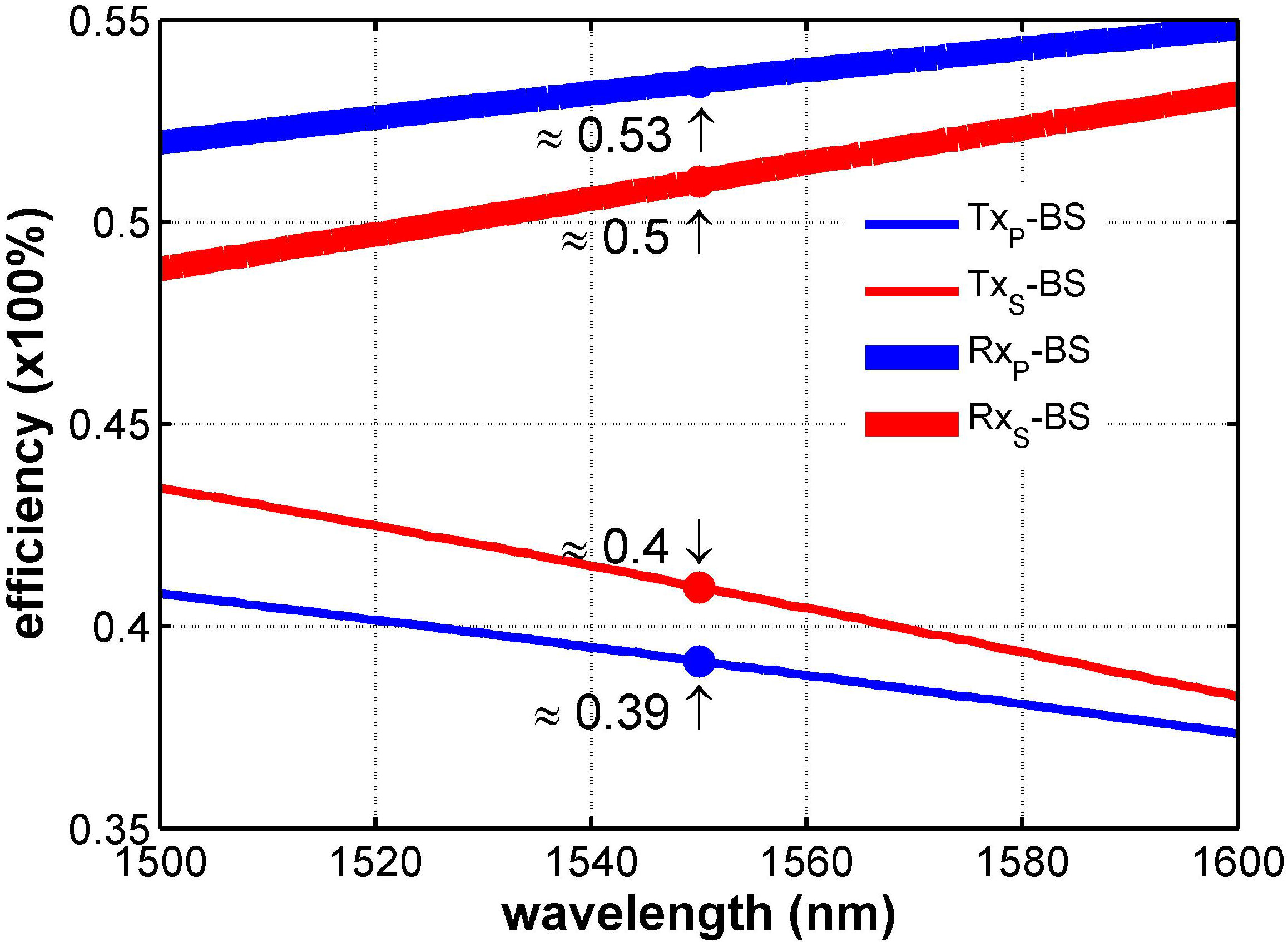
FIGURE 1 Transmittance - Reflectance characterization for BS depends on S and P polarization states.
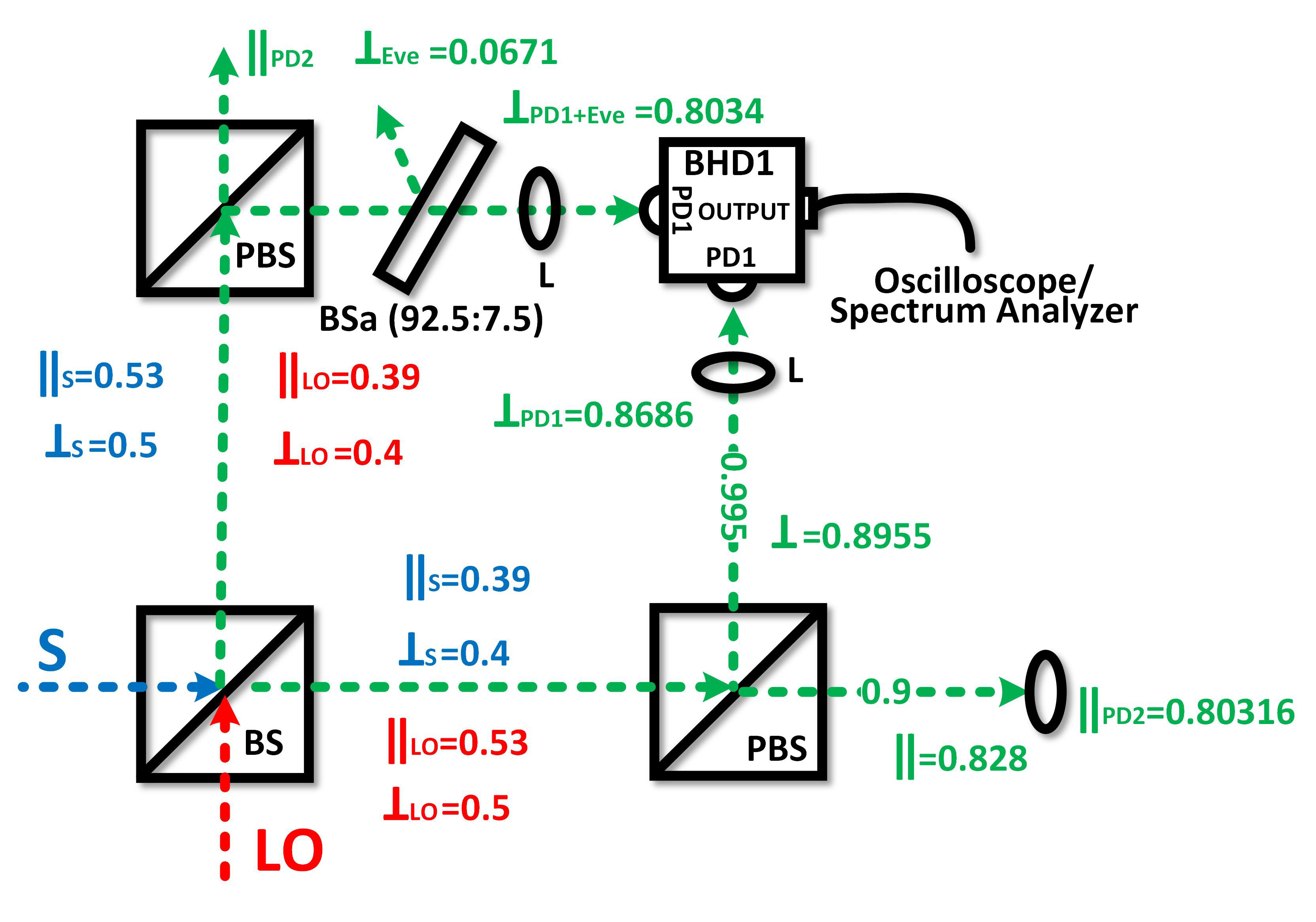
FIGURE 2 Implementation and characterization of the complete experiments using realistic BS, PBS, and lens. The green trace represents the mixed signal.
Among the passive optical devices used in the experimental set-up are the Beam Splitter (BS), the Polarized Beam Splitter (PBS), and the Lens (L), which present nonidealities that affect the performance of the QKD system as was mentioned. Therefore, initial characterization is needed to perform a holistic and optimal design of QKD systems. Firstly, Fig. 1 shows the experimental characterization of a BS used considering the optical signal P-polarized (∥) and S-polarized (⊥) for transmission (T
X
) and reflection (R
X
) modes from 1500 to 1600 nm, making emphasis at 1550 nm. To clarify, Eq. (1) represents the transfer matrix of the BS. In particular, input ports are represented by a
1 and a
2, while the output ports are b
1 and b
2. Thought an optical field, the fraction of optical power coupled considering the input and output ports is represented by
As can be seen, the BS has a higher reflectance efficiency (R XS − BS ≈ 0.5, R XP − BS ≈ 0.53) for both polarizations. However, the transmission efficiency for both polarization states is lower (T XS − BS ≈ 0.4, T XP − BS ≈ 0.39), which implies a loss of optical power that will affect the information transmitted in this polarization state. Although the argument presented is well known for the classical optical set-up (i.e., experiments based on large photon amount per transmitted bit), the implications in quantum experiments are extreme, e.g., such implications are related to the level of security of systems based on quantum optical states and also with the quantum erasing phenomenon [17].
Then, Fig. 2 shows the experimental values of the transmission and reflection efficiencies related to the characterization of all-optical devices used in Bob, being the π/2 optical hybrid based on SOPs the receiving structure used and analyzed. In this context, the maximum efficiency value is 1, so it represents either the transmittance and reflectance efficiencies of 100%. Because the efficiency of each device is independent of other devices, and since the optical beam is transmitted or reflected by different optical devices, the total efficiency is calculated by multiplying the efficiencies of all the devices that are in a particular optical path. Also, Fig. 2 shows how the local oscillator (red trace) and the optical information signal (blue trace) are mixed, and the signals are transmitted and reflected by BS, PBS, and L (with anti-reflection coating at C-Band) according to their efficiencies. In particular, the efficiency of the BS was presented in Fig. 1. The PBS presents an efficiency of ≈ 0.9 and ≈ 0.995 for P-polarized and S-polarized signals, respectively. Also, the transmission efficiency of the lens used is ≈ 0.97. Thus, Fig. 2 shows the particular measurements at each point of the Bob setup used (more details of the set-up in [15,16]) for both SOPs, where it is possible to observe unbalanced optical paths, i.e., the optical path representing the P-polarized signal has less optical power ≈ 0.80316, in comparison with the S-polarized signal ≈ 0.8686. In particular, the analysis of the Alice setup is not crucial at the moment since the scheme is general, although it can be consulted in [15,16]. Next, the S-polarized and P-polarized signals are photodetected by Balanced Homodyne Detectors (BHD1 and BHD2, respectively, BHD2 is not shown) to be analyzed (using an oscilloscope and an electric spectrum analyzer), perform the phase lock and obtain the data transmitted.
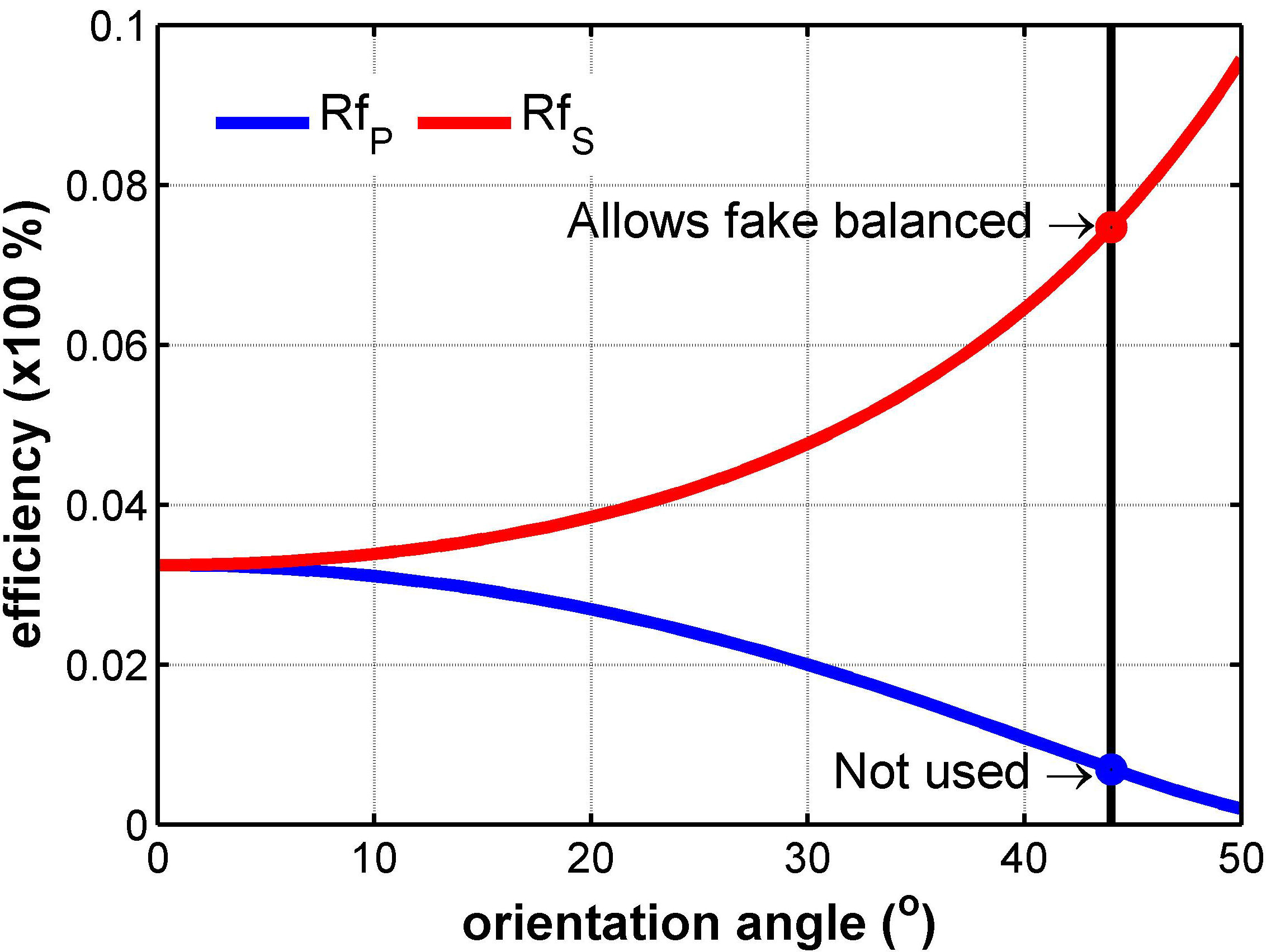
Usually, unbalanced optical paths are corrected using an intentional modification of the original optical alignment or adding attenuators to reduce the optical power; however, this can provide an opportunity for possible side-channel attacks based on back-reflection, power capture side, novel beam splitting attack (middle-man attack), among other important variants [18]. In our case, a Beam Sampler (BSa) is used to intentionality calibrate the optical power in the optical path that presents more optical power, which is the optical path where the S-polarized signals are transmitted. The calibration implies the reflection of a low optical power signal called sampler, which can be used by Eve systems. Thus, this intentional calibration is defined as a Fake Calibration Attack (FCA). In particular, the BSa is fixed with a particular orientation (44°) to produce a transmission efficiency of ≈ 0.925 and a reflectance efficiency of ≈ 0.075 (i.e. 92.5:7.5) that allows Eve to stole ≈ 0.0671 optical power (see Fig. 3) in data burst mode (see Fig. 2), equivalent to 0.01 photons/pulse, meaning that Eve system can steal on average 1 photon after 100 pulses. In particular, Fig. 3 shows the reflection (Rf) of BSa for different orientations and SOPs, where the S-polarized (⊥) mode is used to perform the fake calibration, i.e., the Rf S is used for the FCA, while the Rf P does not correspond to the FCA process because the P-Polarized signal is not attenuated.
3. Results and analysis
Finally, Fig. 4 shows the SQL calibration for the S-polarized signal as part of the FCA process to achieve the optical power balance, from ≈ 15.39 dB to ≈ 15 dB using a Balanced Homodyne Detector (BHD1) with extra-low Noise Equivalent Power and
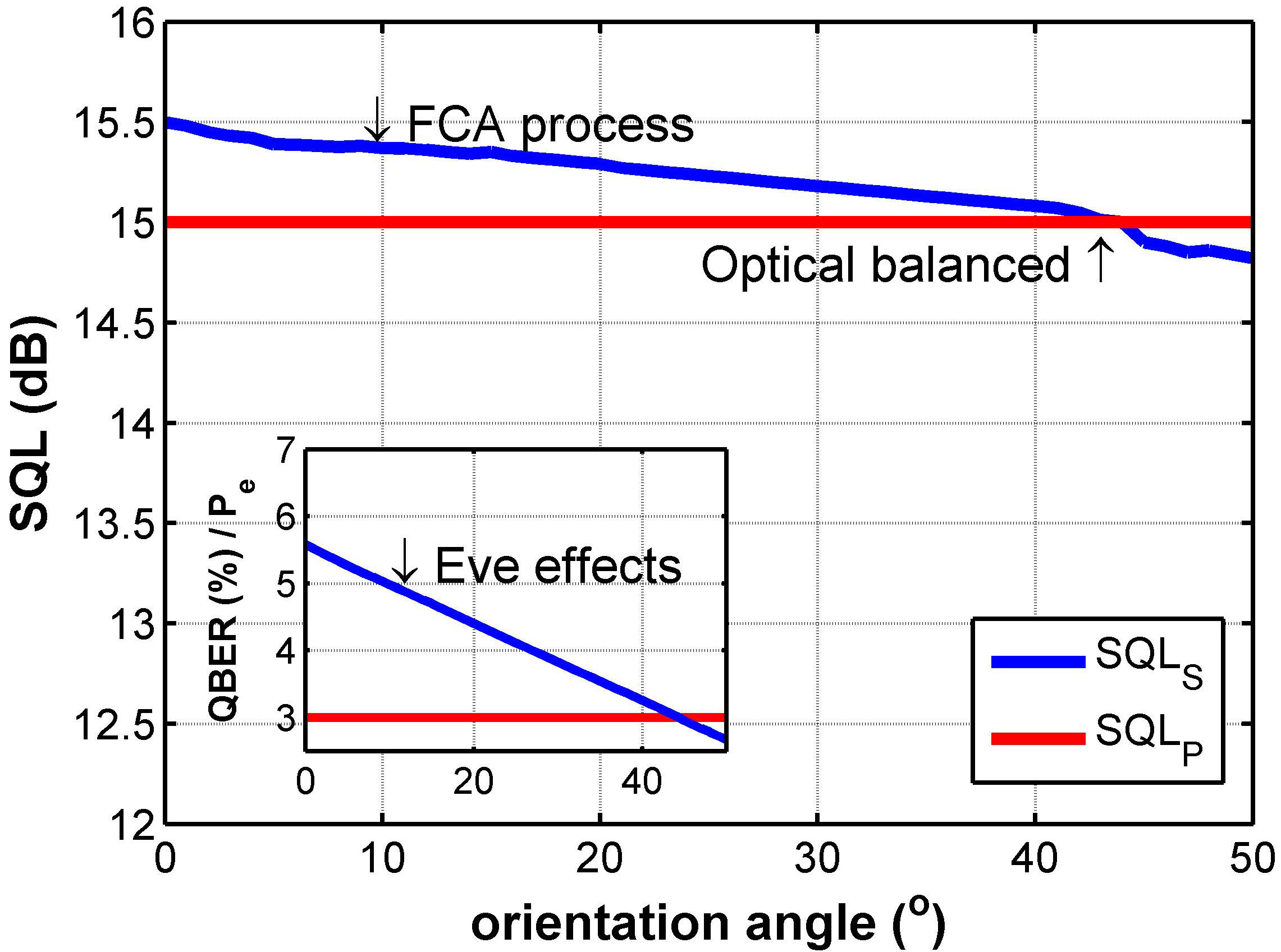
Thus, at 44°, the SQL related to the photo detected S-polarized signal (SQL S ) is the same as the SQL for the P-polarized signal (SQL P ). It is important to mention that the SQL P value is the reference because the P-polarized signals are not attenuated as part of the FCA process, i.e., the SQL P imposes the performance limit for the QKD system. Besides, the subplot in Fig. 4 shows the Quantum Bit Error Rate (QBER or Probability error (P e )) results affected by the FCA process performed by Eve system. In particular, without the FCA process, the QBER ≈ 5.8 %, i.e., considering an unbalanced optical power related to the S-polarized and P-polarized photo detected, where the optical power related to S-polarized signal affects importantly. To clarify, in this case, the Eve system could have the opportunity of making an attack and steal information about the S-polarized signal. However, when the FCA process is implemented, the QBER is reduced to ≈ 3%, so the SQL calibration allows to reduce by 2.8 %. Before the FCA process, the excess of SQL S imposes an important advantage to any Eve system, because they can steal information without being detected, i.e., the spy actions could not be distinguished due to the excess of QBER of ≈ 2.8%.
4. Conclusion
This paper presents the performance of a CV-QKD system affected by an erroneous calibration, called Fake Calibration Attack. The performance is on the QBER, considering the SQL’ calibration for each signal with a particular state of polarization. Although conventional performance measurements for CV-QKD systems are commonly based on the excess noise of the quantum channel as the key parameter in the security analysis for a particular protocol, this paper is focused only on the set-up of Bob in order to support the argument that Bob is a reliable system. However, this analysis is possible to extend to the Alice set-up. In addition, this paper shows a highlight consideration of the QKD system implementation, because in general, realistic channels, sources, and detectors are being considered, but the real implementation and trade-offs regarding passive optical devices are not deeply considered [19]. Also, the results showed are complementary with those process used to determine the optimal point-to-point rates that are achievable by Alice and Bob systems [20].

