


 text new page (beta)
 English (pdf)
 Article in xml format
 Article references
 Send this article by e-mail
 Cited by SciELO
  Similars in
SciELO
Similars in
SciELO 
 Permalink
1.Introduction
Carbon is a versatile element that can combine with itself, being capable of forming different types of hybridizations, giving rise to a wide diversity of nano-structural solid forms. The synthesis of carbon-based structures has been focused on the research of nanotubes 1,2 and recently, in graphene 3,4. This is because of its properties for the electronic and energy industries as well as for structural applications in aeronautic, automotive, and aerospace industries. The main technique for their synthesis is based on the chemical vapour deposition (CVD). This is because it is a method with great scalability and low-cost suitable for the high-yield growth of nanotubes 5 and large-area synthesis of graphene 6. In this respect, the versatility of using CVD allows the use of different kinds of substrates as well as a wide range of catalytic sources for their production 7-10. In addition, the use of CVD allows the production of other allotropic carbon forms with interesting properties: the growth of carbon onions 11 for potential applications under tribological conditions or the synthesis of graphene nanoribbons 12, which in comparison to nanotubes, make them better candidates for the fabrication of nanoscale electronic devices due to their electronic and magnetic properties.
For these reasons, in this work, a micro-structural characterization, mainly based on electron microscopy of several carbon structures obtained by CVD on Inconel 600 (Inconel), has been carried out.
2.Experimental procedure
A schematic diagram of the CVD system is shown in Fig. 1. It is constituted by two heating zones. The first one involves a metallic chamber, which is heated by an electrical resistance. In this chamber, the Ar carrier gas (99.999 %), as well as the solution was injected. The temperature in this zone was set to 180∘C, which allowed the vaporization of carbon source (ethanol) and the transition from solid to liquid stage of the catalyst precursor (ferrocene), fed into the system by a peristaltic pump. The mixture was vaporized and transported into a chamber constituted of a vycor tubing. Inside of the second chamber, it was placed a thin foil of Inconel 600 (Inconel, 0.15C, 17Cr, 0.4Cu, 8Fe, 0.8Mn 73Ni and 0.3Si) of 140 (length) × 7 (wide) × 1 mm (thick). A water trap was used at the end of the system in order to keep an inert atmosphere during the whole experiment. After the reaction took place, the furnance was slowly cooled down to room temperature by holding the Ar flow. Allotropic carbon forms (ACF) were produced according to the synthesis conditions given in Table I .
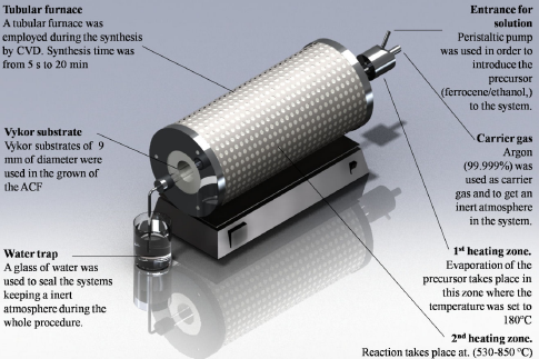
TABLE I Synthesis conditions for the production of allotropic carbon forms. Other fixed conditions were flow of precursor solution 1 mL/min; concentration of ferrocene 4:945 x 10 -3 mol/L.
| Sample | Furnace temperature (oC) | Flow of carrier gas (sccm) | Synthesis time (min) |
| A | 850 | 500 | 20 |
| B | 650 | 150 | 20 |
| C | 650 | 500 | 5 |
| D | 650 | 500 | 1 |
| E | 650 | 500 | 20 |
| F | 650 | 500 | 0.25 |
| G | 650 | 500 | 1 |
| H | 650 | 500 | 0.08 |
| I | 650 | 500 | 0.25 |
| J | 530 | 500 | 20 |
Microstructural characterization was carried out by means of field emission scanning electron microscopy (FESEM) in a JEOL JSM-7401F operated at 3 to 5 keV and high resolution transmission electron microscopy (HRTEM) in a JEOL JEM-2200FS operated at 200 keV. In addition, elemental analysis was achieved by means of energy dispersive X-ray spectroscopy (EDS) in an Oxford Inca microanalysis system attached to the electron microscopes.
3.Results and discussion
Figure 2 displays secondary electron FESEM micrographs of nanotubes. Results from experiment A are shown in Fig. 2a, which shows large bundle arrays of CNTs densely packed grown on the Inconel surface. The length of the CNTs shown is about 150 to 200 nm with diameters (inset in Fig. 2a) in the range of 20 nm, according to the synthesis conditions given in Table I. Experiment B, shown in Fig. 2b, displays displays similar arrays in their morphology with a noticeable decrement in their length due to an inferior synthesis temperature (650∘C) compared to the temperature synthesis of experiment A (850∘C).
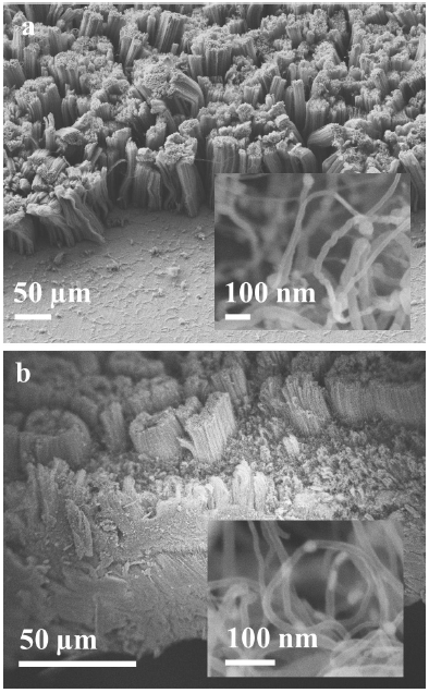
FIGURE 2 Bundle arrays of nanotubes. a) Experiment A. The inset displays nanotubes in the range about 20 nm. b) Experiment B. A notable reduction in their diameter is observed (10 nm).
A change in the flow of the Ar carried gas from 500 sccm to 150 sccm produces nanotubes with a length about of 50 nm. However, the inset given in Fig. 2b shows nanotubes with diameters in the range of 10 nm, which indicates a notable reduction in the number of walls and a transition from multi-walled to few-walled structures. From the above observations, it can be noted that the adequate selection of the synthesis temperature and the flow of the carrier gas can lead to the formation of single-walled nanotubes. No traces of carbonaceous particles were observed under these experimental conditions. Bundle arrays with a homogeneous morphology were observed along on the Inconel substrate for the selected synthesis conditions mentioned above.
Figure 3 shows FESEM micrographs of the Experiments C, D, and E respectively with variations in the synthesis time. Figure 3a presents nanotubes randomly dispersed. An adjustment to 5 min in the synthesis time was done. A hexagonal carbonaceous particle attained to the nanotubes structure is observed A close-up to an isolated hexagonal particle onto the Inconel surface is observed in the inset of Fig. 3a. Its morphology consists of three edges from a partial view of a hexagonal crystal. Their largest edge is about 1.5 μm of length. This morphology suggests a 2D atomic structure commonly associated to Bernal-stacks graphene observed by other authors 13. The decrement in the synthesis time (5 min, Experiment D) seems to have a direct effect on the formation of these 2D structures. A decrease in the synthesis time to 1 min, produces an increase in the number of hexagonal particles on the Inconel substrate; however, the length on their edges shows a clearly decrease of their size of about 150 nm. By increasing the synthesis time to 20 min (Experiment E), it is visible the formation of nanotube structures; their diameters are in the range of 8 to 12 nm indicating few walls in their inner arrays. Nevertheless, their morphology spherical carbonaceous particles (SCP) on their surface probably formed as graphitic onions, in necklace-like arrays of CNT-SCP-CNT.

FIGURE 3 Different carbon structures. (a) Experiment C showing a hexagonal-shaped carbon structure on a nanotube. (b) Experiment D displays hexagonal carbon particles among nanotubes randomly dispersed on the Inconel substrate. (c) Spherical carbon particles and nanotubes in like-necklace arrays from Experiment E.
Bright field high-resolution transmission electron microscopy (TEM) micrographs corresponding to nanotubes observed in experiments F and G, respectively (Fig. 4). Double- and triple-walled CNTs are given in Fig. 4a for the Experiment F. Nanotubes with diameters of about 5 nm with a well definition in their wall morphology indicate a high degree of crystallinity. A synthesis time of 0.25 min, allows the formation of nanotubes with well-defined walls. The alteration in the parameters related with the synthesis conditions allows the production of thinner tubes; nevertheless, their quantity produced is limited compared to previous results. By increasing the synthesis time (1 min) and the precursor concentration (∼0.005 mol/L), coarser tubes are obtained as shown in Fig. 4b (Experiment G). A typical multi-walled crystalline structure with a inner hollow is displayed. The outer diameter of the tubes varies from 7 to 15 nm in range. Nor ferrous nor carbonaceous particles are observed.

FIGURE 4 Bright field TEM micrographs. (a) Double-walled nanotubes from Experiment F and (b) multi-walled nanotubes from Experiment G.
Figure 5 shows bright field TEM micrographs of several allotropic carbon forms of different structures obtained from variations in the synthesis time (Experiments E, H, and I, respectively). A deeper analysis carried out by TEM in the experiment E (Figs. 5a and 3c) indicates the formation of onion-like carbon particles (inset) of 10 nm of diameter covered by a multi-walled nanotube structure. Note that the maximum diameter of the CNTs does not exceed 20 nm. It is noticeable how the formation of the arrays between the nanometric tubes and the graphitic onions is highly influenced by the synthesis time compared to the synthesis conditions employed in Experiments F and G, respectively, where few walled nanotubes were produced without the presence of carbonaceous particles. From the previous experiments, a dramatic reduction in synthesis time was used in Experiment H (Fig. 5b and 5c). Few-layered graphene are identified near to the carbon film of the TEM grid. It is visible the effect on the carbon structure caused by the reduction of the synthesis time giving as a result graphene structures derived of the use of ethanol in CVD processes. A different zone of the same TEM sample shows an increased number in the graphitic stacked layers, which indicates zones on the Inconel support where graphene was deposited with heterogeneously in their layers during their growth. However, a specific selection of synthesis conditions by using the precursor and the system described in this work suggest the formation of large-area graphene sheets. With an slightly increment in the synthesis time to 0.25 min, the formation of concentric carbon layers, whose morphology is attained to graphitic onion structures is observed in Fig. 5d. Carbon onion were observed randomly dispersed on the TEM grid according to the synthesis conditions given for Experiment H. Particles with an outer diameter ranging from 20 to 30 nm were produced.

FIGURE 5 Different carbon structures. (a) Experiment E where carbon spheres are attained to the nanotubes. Experiment H displayed (b) few-layered and (c) multi-layered graphene sheets and (d) onion-like carbon sphere from Experiment I.
Results from TEM analysis in Experiment I, are given in Fig. 6. A concentric array of pentagonal rings is shown in Fig. 6a. These arrays are similar to those achieved by variations in the temperature gradient by experimenting with electric arc and reported by Ugarte 14. A comparison with the previous onion particles observed above (Fig. 5d, experiment H), suggests an important effect of the temperature and synthesis time over the carbon onion morphology. Additional analysis on the Experiment I allows the observations of multi-walled nanotubes (inset) and a carbon nano-ribbon with a very similar morphology to those reported by Zhang et al., (15) by the unzipping of multi-wall nanotubes (Fig. 6b).

4. Conclusions
The synthesis of double- and few-walled nanotubes onto an Inconel surface was obtained and characterized in this work. However, variations in the synthesis conditions can lead to the formation of different carbon structures on the Inconel support, as presented above. It was observed how the synthesis conditions have a high influence over the carbon final products. The formation of double-walled nanotubes was achieved in Experiment F; however, few-layered graphene structures were obtained by using the synthesis conditions of Experiment F, only reducing the synthesis time to 0.08 min. From the above observations it is important to highlight appropriate selection in the synthesis condition in order to avoid or to obtain different carbon-based structures. Alternative studies of different carbon structures, such as those reported in this work, are being carried out by the present authors.

