


 nueva página del texto (beta)
 Inglés (pdf)
 Artículo en XML
 Referencias del artículo
 Enviar artículo por email
 Citado por SciELO
  Similares en
SciELO
Similares en
SciELO 
 Permalink
1.Introduction
Gas sensors based on semiconductor oxides are very useful nowadays; Their sensing properties allow establishing the presence of either oxidizing or reducing species. Working principles of gas sensors based on thin films have been widely reported in several papers and books 1-5. Charge releasing is due to the reducing process in the presence of a reducing agent, and this can be quantified by a very complex system. This is made with the aid of a sensitive layer, usually semiconductor oxides thin films, like SnO2 and ZnO, for instance. In this project, athin film sensor was deposited by spray pyrolysis technique, and patterned by lift-off technique, then thin films with a thickness ranging from 200 nm to 245 nm were used. Floating-gate metal oxide semiconductor (FGMOS) is very similar to metal oxide semiconductor field-effect transistor (MOSFET), but they have an isolated polysilicon layer between the conventional gate and the gate area and are very versatile electronic devices; one of the FGMOS applications are artificial neural networks (ANN) since they can be implemented within systems which emulate, for example, the biological brain, so they give an output signal in relation to one or several input signals. Hence, the approximation presented in this paper is directed to show the operation of a gas detection system based on a FGMOS, as a different alternative from those already reported, that take advantage of the resistance variation of sensitive thin layers made from semiconductor oxides.
1.1.Floating-gate MOS transistor (FGMOS)
Floating gate CMOS transistors (FGMOS) are a variant of a conventional Complementary-MOS (CMOS) transistor. The difference between FGMOS and CMOS transistors is that the former has an isolated layer of polysilicon between the gate and the channel area, which provides a capacitive effect that will affect the threshold voltage of this device 6-11.
The experimental design explored in this paper places a sensitive film in direct contact with the floating gate of a FGMOS. Once in contact, a charge is produced as a result of the chemical reaction that occurs when a gas is detected by the thin layer. We can interpret this reaction as a variation of oxidizing or reducing agents 3,12. It is important to differentiate the mechanism that creates this charge, as there are two very well-known methods for programming a FGMOS: hot electron injection (HEI) and Fowler-Nordheim tunneling (FN). The charge generation mechanism presented herein does not require using any of these traditional electrical methods, but the charge will be caused by the chemical reaction mentioned above. Therefore, this process will be called chemical injection due to the chemical nature of the generated charge; however, the behavior is similar to FN tunneling. The equivalent circuit for this mechanism is shown in Fig. 1, in this model the resistance represents the oxide present with a very large value because it is an insulator so, V tun is the difference between the injector potential (V ti ) and the floating gate potential (V − fg); and Eq. (1) denotes the behavior of the floating gate voltage V fg .

Where V fg floating gate potential, K 0 injector coupling coefficient, K cg control gate coupling coefficient, V cg potential applied to control gate, Q fg charge stored in the floating gate, and C tot total capacitance.
From (1) it can be seen that the voltage on de floating gate (FG), V fg , is a fraction of the voltage applied to the control gates included in the FGMOS, where this fraction is determined by the coupling coefficient, K 0 . Therefore, the floating gates can be considered as weighted inputs in applications such as ANN. Coupling coefficients can be obtained from the equivalent capacitive model (Fig. 2), where each applied potential is associated with their respective capacitance, which in turn, determines both the floating gate voltage and the drain current.

From the equivalent circuit, floating gate voltage V fg can be found by superposition, considering each of the voltages applied to the structure, this is, V cg , V ti ; this can be denoted by (2).
where C pp capacitance between control and floating gates, C i capacitance between the FN injector and FG, and C ox channel capacitance.
So, Eqs. (1) through (5) briefly explain how FN tunneling can modulate the threshold voltage of a FGMOS, injecting/extracting charge as a function of the magnitude of an electric field between the injecting nodes. However, as indicated in Eq. (1), any charge present in the floating gate due to a mechanism different from that of an electrical nature has an important role. Then, as mentioned above, the interaction between the sensitive thin layer and the sensing gas species, results in a charge that can also have the same effect as when either FN or HEI is used to program a FGMOS transistor. As this charge is a function of gas concentration, this chemical injection mechanism can be used also to correlate concentration with the electrical output, using the FGMOS as a transducer.
1.2.Artificial neural networks
Usually, an artificial neural network (ANN) is a system used for data processing because of the principles of operation of these systems. ANNs have the ability to provide an output signal depending on one or more input signals and these have been extensively studied in numerous books and papers 9,12-17. An ANN is a machine that is designed to model how a particular task or function of interest will be performed, emulating the human brain, whose main characteristic is its adaptability to the surrounding environment 13-15.
The introduction of parallel computing systems is necessary whether we want to achieve real-time responses 12,13,18. These new systems coincide with the development of a very large scale of integration (VLSI) 14,15,19, especially after J.J. Hopfield 20, who introduced new points of view in which neural networks combine the VLSI integration, enhancing hardware approximations of ANNs. In this way and with the discovery of a Multilayer Perceptron, the old objections to ANN because of the problems attributed to the simple perceptron, were solved. ANNs can be constructed with electronic components or should be simulated by software in a digital computer 6,7,9,16,17,18,21,22.
2.Development
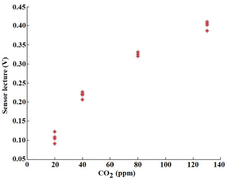
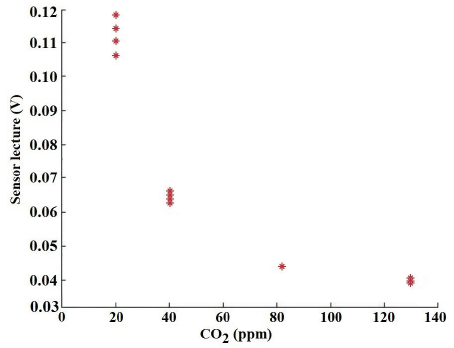
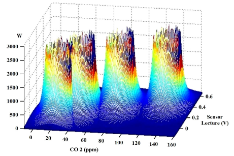
First of all, the intention is to train off-line a neuro-fuzzy network, from experimental data obtained with two conventional sensors that were subjected to a controlled atmosphere of different concentrations of CO2. A Radial Basis Neural Network, with clustering by fuzzy C-Means (FCM), was developed in C * .m files by Matlab. The architecture of this ANN is a three-layered network, with one neuron at the input, a second layer with four, because presents a good performance, and a lower number of neurons is required, finally an output layer with one neuron only. Next, after simulating the neuro-fuzzy network, this will deliver the weights that must be loaded to the floating gate of each FGMOS included in the ANN that will be described below, in order to demonstrate that this kind of network can be used to classify gas concentrations from an electrical output. Figure 3 shows the ANN training by using sensor 1 with several CO2 concentrations (20, 40, 80 and 130 ppm), because based on these results Fig. 3 and 4, 3D clusters (Figs. 5 and 6) and fuzzy sets (Figs. 7 and 8) were obtained. Figure 3 shows that for low concentrations, around 20 ppm, the sensor 1 output signal is about 0.1 V, for 40 ppm match about 0.22 V, for 80 ppm match 0.33 V and finally, for 130 ppm the output signal is about 0.4 V. Note that in this case, the sensor’s output increases as the gas concentration increases. On the other hand, Fig. 4 shows measurements of the ANN using sensor 2 with the same concentrations of CO2. In this case, values obtained are dissimilar compared to measurements delivered with sensor 1, this is, an output voltage of 0.11V was obtained for a gas concentration of 20 ppm, for 40 ppm match about 0.06 V, for 80 ppm match 0.041 V and finally 0.04V for a gas concentration of 140 ppm. The weights of the ANN were computed by a clustering process; therefore, their magnitude can be finally defined; afterward, these weights (W) can be used to train the neural network, by mean of injecting/extracting charge of the FGMOS transistors, the generated 3D clusters are shown in Fig. 5 and 6. As can be noticed, in Fig. 5 value of W is rated around 10000, and in Fig. 6 value of W is rated around 3000, due there are sensors 1 and 2 are different from each other.

Once the weights are determined, the membership functions of the neuro-fuzzy network can be computed. The corresponding fuzzy set membership functions of sensors 1 and 2 are shown in Fig. 7 and 8, respectively. As it can be noticed, the membership functions never exceed the maximum value of one, this means that if an item has a membership function of 1, it will have a total membership to this cluster. In Fig. 7, axis sensor lecture has a range from −1.5 V to 2.5 V, whereas axis CO2 has a range of −200 ppm to 300 ppm, furthermore, the axis of the membership function has values from 0 to 1. In the case of Fig. 8, the axis sensor lecture has a range from −2 V to 3 V and axis CO2 has a range of −200 ppm to 300 ppm too.


Designed circuit
As is well known, an ANN has the ability to determine the gas concentration for such a voltage response of the sensor. After several tests carried out by Orcad® software, the optimal configuration of an ANN that can generate an adequate Gaussian function was determined. This function can be carried out by FGMOS inverters. For this reason, optimum dimensions and coupling capacitances of some transistors must be calculated.
An array of N and P channel FGMOS transistors was designed to implement the ANN; three inverters are interconnected with each other. The design is shown in Fig. 9. As it can be appreciated, P1 and N1 transistors form the first inverter, P2, N2, P3, and N3 transistors form a double inverter, and P4 and N4 transistors work as an output stage. The input signal or VG1 is connected to the first and the second inverter inputs (P1, N1, P2 and N2 gates).

The first inverter output is joined to the gate of N4, the second inverter output is connected to the third inverter input (P3 and N3 gates), and the output of the third inverter is connected to the P4 gate. P4 and N4 drains are connected to a resistance of 100 MΩ.
Figure 9 shows three inverters and a couple of transistors as an output stage. The first inverter was programmed to get an inversion with a low voltage input (input or VG1) of around 0.4 V, next, the second and third inverters form a double inverter, which was programmed to have an inversion around 1.5 V. Finally; based on these couple inversions, the last stage can deliver a Gaussian function (output). The drawback of this configuration is that there may be some spreading due to both transition voltages, and also due to the handling of a high number of variables as a result of the number of transistors used.
To reduce these issues, an alternative circuit was proposed, which can help in discarding the negative effects of these variations. However, the result is the same to obtain a pseudo-Gaussian response having a voltage ramp as an input signal, despite the inclusion of an operational amplifier and external resistances 9,17,21, as is shown in Fig. 10. This alternative circuit has two inverters, similar to the first and the second inverters from Fig 9. In this case, input signal or VG1 is connected to the first and second inverter inputs (P5, N5, P6 and N6 gates), and the first and second inverter outputs are connected to the input differential pair (M3 and M4 gates) of the opamp, M7, and M8 drain are opamp output. Within the simulation, the iterative method named gradient descent was used to automatically adjust charge over the floating gate of each FGMOS used in this configuration. This method allows for good adjustment when the purpose is to tune a great number of parameters when a particular function is searched, as is the case for this alternative circuit. The parameter adjustment is made based on the difference between the output Gaussian function of the alternative circuit of Fig. 10. If there is a minimum difference or error, the value obtained is raised to the cubic power and multiplied by an adjustment factor. Due to the cubic exponent, the error sign is kept while the adjustment factor limits the new adjusted value, then adding or subtracting the corresponding value for each floating-gate.

Responses of the alternative circuit from Fig. 10 are shown in Fig. 11(a) for charge adjusting, the desired function is very approximate to the searched function. the voltages that should be loaded to the floating gate: V(FGN1)=1 V, V(FGN2)=0.75 V, V(FGP1)= − 0.4 V and V(FGP2)= − 0.75 V, 11(b) for desired function vs approximated function, 11(c) for adjusting error and 11(d) for charge adjusting signal; it can be seen that after a relatively few numbers of iterations (70), considering the adjustment of the output signal shown in 11d, an error reduction is noticed from iteration 10, so the accuracy of the system is calculated to be ±0.019 V. Hence, after training the ANN with experimental data of gas concentrations, these voltages must be present on the respective floating gates to be able to classify correctly any gas concentration sensed for any concentration measured.

FIGURE 11 Whole process for parameters adjusting of alternative circuit, a) Charge adjusting, b) Desired function vs. approximated function, c) Error between desired function and approximated function and d) Charge adjusting signal.
Following this methodology, it is critical that the pseudo-Gaussian function can be modified in height, width, and position, depending on how it is needed for data processing. Therefore, it is demonstrated that functions can be approximated to the desired one with off-line training. As a result, desired functions were obtained, and the ANN was trained as it was described above. With this procedure, any ANN shall be able to traduce a concentration value from a chemical injection to an electrical reading. The Gaussian shapes that will operate the ANN are shown in Fig. 12.

3. Comparisons between simulations and measurements
Experimental measurements of conventional gas sensors were compared against the response, of the ANN designed with FGMOS transistors, with the aim of verifying whether the developed ANN performance is as expected, Fig. 13 plots the experimental CO2 measurements with a relative humidity (RH) of 10%, versus the output values of the ANN. It is worthwhile to mention that the y−axis plots 100 different voltage outputs for known gas concentrations taken randomly, just to prove that the trained ANN follows correctly the measured values. It can be seen that very similar behavior is obtained between the design need ANN and the experimental measurements. This means that it is an appropriate approximation having very acceptable performance. This plot demonstrates that this ANN has a suitable performance because there are minimal differences.

FIGURE 13 Real concentration vs approximate concentration using a silicon ANN based in FGMOS transistors, measurements were made within the training range for CO2, with a relative humidity of 10 %.
Another comparison was made with 110 measurements of NO2; in this case, once again similar behaviors were noticed with a minimal difference between the ANN and the experimental measurement (Fig. 14).

FIGURE 14 Real concentration vs approximate concentration using a silicon ANN based in FGMOS transistors, measurements were made within the training range for NO2.
Finally, a comparison using 120 measurements of CO2 (no relative humidity present) vs ANN values was carried out. Again, similar behaviors can be appreciated with minimal differences between ANN and the experimental measurements. This can be seen in Fig. 15. Relative errors for each case are between 6% and 11% respectively.

4.Conclusions
Sensors’ thin films give very low current values when both desorption and adsorption phenomena are carried out in the presence of oxidant and reducing species. The reducing effect releases a lot of surface charges, so these charges are introduced into a floating gate of a MOS transistor by chemical injection effect. The Perceptron ANN was chosen for gas correlation to electrical output, because it is a very useful technique for handling information. Such information is provided by a gas sensing system. The ANN proposed can be implemented in silicon using FGMOS transistors through an array of several appropriate inverters. Therefore, a reliable pseudo-Gaussian function could be obtained, and in addition, can be implemented within the design of an ANN. Two arrays of FGMOS inverters were proposed using FGMOS transistors, which led to the configuration of configurable pseudo-Gaussian functions. Also, Perceptron ANN was developed, and its weights were calculated by a clustering process. These weights were used to train the neural network, so they could be loaded by the injection/extraction on the floating gate of FGMOS transistors for signal processing circuit configuring. A neuro-fuzzy stage was proposed and developed. The behavior of the Perceptron ANN was verified through a comparison between experimental measurements and the concentration value within the training range. Measurements were carried out with pure NO2, pure CO2, and CO2 with 10% of RH. The behavior was similar in the three cases, which indicates that for different types of species, the ANN has a very satisfactory behavior.

