


 text new page (beta)
 English (pdf)
 Article in xml format
 Article references
 Send this article by e-mail
 Cited by SciELO
  Similars in
SciELO
Similars in
SciELO 
 Permalink
1. Introduction
From the analysis of the phase diagrams of I2VI-IV2VI3 pseudo-binary systems (where I = Cu or Ag; III = Ga or In; and VI = S, Se or Te), the formation of the I3-III5-VI9 ternary semiconducting compounds has been shown [1]. The chemical formula of these materials, which have a deficiency of one cation over the anions, can be written as I3-III5-(-VI9 where ( represents the cation vacancy. Also, the existence and stability of these I3-III5-VI9 compounds can also be explained [2] as due to the presence in I-III-VI2 chalcopyrite structure compound of interacting (III+2I + 2V-1I) donor-acceptor defect pair which is electrically inactive and thus, do not contribute to the total charge carriers. For these reasons, they are known as Ordered Vacancy (OVC’s) or Ordered Defect Compounds (ODC’s). The semiconducting behavior of these OVC’s has been explained, based on the four electrons-per-site rule, by assigning to this vacancy a zero valent atom [3].
Some compounds of the Ag3III5VI9-type, as for example Ag3Ga5Se9, Ag3Ga5Te9 and Ag3In5Te9 have received considerable attention lately as potential candidates for several applications as photo-absorbers in solar cells, opto-electronics devices, and photoelectrochemical cells [4], whereas Cu3Ga5Te9 [5,6] and Cu3In5Te9 [7] are of great interest for thermoelectric applications. As regards to the crystal structure of these I3-III5-VI9 compounds, although several studies on the indexing and space group assignation have been reported for various authors from powder X-ray diffraction analysis, some controversy still exists about this subject in these materials (for details, see Table I, where crystals systems, space groups and unit cell parameters for the I3-III5-VI9 compounds are listed). In any case, a detailed structural study was conducted.
Table I Crystal data for ternary I3-III5-VI9 (I = Ag,Cu, III = Ga,In, VI = Se,Te) compounds.
| Compound | System | Space group | Unit cell parameters (Å,°) | Ref. |
| Ag3Ga5S9 | Tetragonal | P4 or P4mn | 5.759(1), 10.314(3) | [8] |
| Ag3Ga5S9 | Orthorhombic | Pmm2 | 9.767, 5.257, 9.225 | [4] |
| Ag3Ga5S9 | Orthorhombic | Pmm2 | 15.94(6), 4.512(4), 7.164(8) | [8] |
| Ag3In5S9 | Monoclinic | P2 or Pm | 10.813(5), 7.661(4), 4.362(1), 91.7(3) | [8] |
| Ag3In5S9 | Tetragonal | P4 or P4mn | 6.714(2), 10.430(4) | [8] |
| Ag3In5S9 | Tetragonal | N.I.* | 7.21, 14.57 | [9] |
| Tetragonal | N.I. | 8.738, 7.147 | [9] | |
| Cu3Ga5S9 | Hexagonal | P6/mmm | N. I. | [10] |
| Cu3Ga5S9 | Orthorhombic | Pmm2 | 21.947(5), 3.977(1), 5.581(1) | [8] |
| Hexagonal | P6/mmm | N. I. | [10] | |
| Cu3Ga5Te9 | N.I. | N.I. | N. I. | - |
| Cu3In5S9 | Monoclinic | N.I. | 6.6, 8.12, 6.91, 89.0 | [11] |
| Cu3In5Se9 | Orthorhombic | Pmm2 | 9.767(2), 9.225(5), 5.257(2) | [12] |
| Tetragonal | P42c | 5.7630(4), 11.5370(8) | [13] | |
| Cu3In5Te9 | Hexagonal | N.I. | 8.78, 18.66 | [1] |
| Orthorhombic | Pmm2 | 12.364(3), 4.374, 11.118(5) | [8] | |
| Tetragonal | P4 or P4mn | 8.738 (3), 7.147(2) | [12] | |
| Tetragonal | P42c | 6.185(1), 12.41(1) | [13] | |
| Tetragonal | I4 | 6.1836(2), 12.400(1) | [14] | |
| Tetragonal | P42c | 6.1852(2), 12.3633(9) | this work |
*N. I. = No information about this item is given in the literature
As observed in this Table, hexagonal, orthorhombic and tetragonal crystal systems have been reported for Cu3n5Te9. Recently, in an attempt to analyse its crystal structure, Guedez et al. [14] have assigned to this compound the tetragonal space group I4 However, since incorrect ion distribution and occupancy factors were achieved in this analysis, the stoichiometric composition thus obtained, which is Cu0.924In1.301Te9.545, greatly disagrees with the nominal composition Cu3In5Te9. In addition, this cationic and anionic distribution derives at a Cu-Te bond distance greater than that of In-Te bond, which gives no chemical sense to this structural model.
For this reason, in order to derive a model that explains well all the X-ray diffraction peaks observed in the powder pattern of this compound, to clarify the discrepancy related to its crystal structure, and to refine it by means of the Rietveld method, a detailed structural analysis of the ordered vacancy compound Cu3In5◻Te9 using powder X-ray diffraction was performed.
2. Experimental
Samples of Cu3In5Te9 used in this study were prepared by the vertical Bridgman-Stockbarger technique. Stoichiometric mixture of highly pure components of Cu, In and Te (99.999%) were sealed in an evacuated ampoule. Initially, the ampoule was heated from room temperature to 1170 K at a rate of 20 K/h. The molten mixture was then heated to 1370 K at 10 K/h and kept at this temperature for 12 h. To assure a homogeneous mixing the ampoule was agitated periodically. It was later cooled at 10 K/h to 1090 K, and at 5 K/h to 800 K. The ingot was annealed at this temperature for 120 h. The furnace was then turned off and the ingot cooled down to the room temperature.
The chemical analysis of samples taken from the central part of the ingots, performed by Energy Dispersive X-ray Spectroscopy (EDS), gave representative compositions of Cu: In: Te as 16.58:30.00:53.42 at. percentage, respectively, very close to the 3:5:9 ideal value. There is, however, a slight deficiency of Cu over In (Cu/In ≈ 0.55) and a slight excess of Te over cations (Te/metal ≈ 1.15).
For the X-ray analysis, a small quantity of the sample, cut from the ingot, was ground mechanically in an agate mortar and pestle. The resulting fine powder was mounted on a flat zero-background holder covered with a thin layer of petroleum jelly. The X-ray powder diffraction data was collected at 293(1) K, in Θ/2Θ reflection mode using a Siemens D5005 diffractometer equipped with an X-ray tube (CuKα1 radiation: λ = 1.54056 Å; 40 kV, 30 mA). A fixed aperture and divergence slit of 1 mm, a 1 mm monochromator slit, and a 0.1 mm detector slit were used. The specimen was scanned from 10-100° 2Θ, with a step size of 0.02° and counting time of 10 s. Quartz was used as an external standard. The Bruker AXS analytical software was used to establish the positions of the peaks.
3. Results and Discussion
The X-ray diffractogram of Cu3In5◻Te9 shows a single phase. The 2Θ positions of the 20 first peaks in the diffraction pattern were introduced into the auto-indexing program Dicvol04 [15], and a tetragonal cell of dimensions a = 6.186(1) Å, c = 12.365(2) Å, were obtained. This cell is similar in magnitude to the parent chalcopyrite structure of CuInTe2, a = 6.194(2) Å, c = 12.416(4) Å [16]. The lack of systematic absence condition h+k+l in the general reflections of the type hkl indicating a P-type cell and rule out the I-type cell of the chalcopyrite structure. In addition, the conditions hhl:l = 2n and 00l:l = 2n suggests the extension symbol P42c.
A search in the Inorganic Crystal Structure Database (ICSD) [17] showed an early report by Hönle et al. [18] of a Cu-poor Cu-In-Se compound β-Cu0.39In1.2Se2, which was solved by single crystal in the space group P42c, known as P-chalcopyrite structure. The similarity in the space group symbol with our structure gave indications that β-Cu0.39In1.2Se2 structure, with cation distribution: Cu1 in 2e (0,0,0); Cu2 in 2b (1/2,1/2,1/2); In1 in 2f(1/2,1/2,0); In2 in 2d (0,1/2,1/4), could be a good starting point to construct the initial structural model for Cu3In5Te9.
Thus, several models were derived from Hönle’s structure by permuting the cations in the available Wyckoff positions.
Table II shows 16 models tested against the diffraction data by means of the Rietveld refinement method [19], all of which have the Cu+ cations (Cu1) placed in the origin with Wyckoff position (2e): 0,0,0 and Cu2-In3 sharing a position with occupancy factors (foc) 0.333 and 0.222, respectively. Other 16 tests were performed where the Cu+ cations moved from the origin, and only poor quality Rietveld refinement fits were obtained, and therefore, not presented here.
The Rietveld refinements were carried out using the Fullprof program [20,21]. The angular dependence of the peak Full Width at Half Maximum (FWHM) was described by the Cagliotti’s formula [22], whereas peak shapes by the parameterized Thompson-Cox-Hastings pseudo-Voigt profile function [23]. The background variation was described by a polynomial with six coefficients, and the thermal motion of the atoms by one overall isotropic temperature factor. From the figures of merit R p , R wp and S, it was inferred that the model that best fit the diffraction data is the No. 2. The results of the Rietveld refinement for this model are summarized in Table III. The observed calculated and difference profiles for the final cycle of Rietveld refinements are shown in Fig. 1. Atomic coordinates, isotropic temperature factor, bond distances and angles are listed in Tables IV and V.
Table II Models employed for the cation distribution in the Rietveld refinement of the ordered vacancy compound Cu3In5(Te9.
| Model | (2e) | (2a) | (2b) | (2c) | (2d) | (2f) | (8n) | Rp | Rwp | S |
| 0,0,0 | 0,0,1/4 | 1/2,0,1,1/4 | 1/2,1/2,1/4 | 0,1/2,1/4 | 1/2,1/2,0 | x,y,z | ||||
| 1 | CU1 | ◻ | Cu2−In3 | − | In1 | In2 | Te | 10.8 | 12.1 | 1.9 |
| 2 | Cu1 | ◻ | Cu2−In3 | − | In2 | In1 | Te | 7.1 | 8.5 | 1.3 |
| 3 | Cu1 | ◻ | In1 | − | Cu2−In3 | In3 | Te | 12.8 | 18.1 | 2.5 |
| 4 | Cu1 | ◻ | In1 | − | In3 | Cu2-In3 | Te | 12.2 | 18.0 | 2.5 |
| 5 | Cu1 | ◻ | In2 | − | In1 | Cu2-In3 | Te | 18.7 | 25.1 | 3.5 |
| 6 | Cu1 | ◻ | In2 | − | Cu2-In3 | In1 | Te | 20.2 | 30.2 | 4.2 |
| 7 | Cu1 | ◻ | In3 | − | In2 | Cu2-In3 | Te | 9.4 | 10.0 | 1.6 |
| 8 | Cu1 | ◻ | In3 | − | Cu2-In3 | In2 | Te | 11.1 | 14.6 | 2.0 |
| 9 | Cu1 | − | Cu2-In3 | ◻ | In1 | In2 | Te | 12.0 | 18.5 | 2.6 |
| 10 | Cu1 | − | Cu2-In3 | ◻ | In2 | In1 | Te | 9.7 | 10.5 | 2.7 |
| 11 | Cu1 | − | In1 | ◻ | Cu2-In3 | In3 | Te | 12.8 | 18.1 | 2.5 |
| 12 | Cu1 | − | In1 | ◻ | In3 | Cu2-In3 | Te | 12.2 | 18.0 | 2.5 |
| 13 | Cu1 | − | In2 | ◻ | In1 | Cu2-In3 | Te | 18.5 | 25.1 | 3.5 |
| 14 | Cu1 | − | In2 | ◻ | Cu2-In3 | In1 | Te | 20.2 | 30.1 | 4.2 |
| 15 | Cu1 | − | In3 | ◻ | In2 | Cu2-In3 | Te | 9.9 | 10.2 | 1.6 |
| 16 | Cu1 | − | In3 | ◻ | Cu2-In3 | In2 | Te | 11.1 | 14.6 | 2.0 |
Cu2 (cation) (foc= 0.333); In3 (cation) (foc= 0.222); Te (anion) : (x ≈ 1/4, y ≈ 1/4,z ≈ 1/8); ◻ = cation vacancy.
Table III Rietveld refinement results for Cu3In5◻Te9.
| Molecular formula | Cu3In5◻Te9 | wavelength (CuKα) | 1.54056 Å |
| Molecular weight (g/mol) | 2063.2 | data range 2θ(°) | 10-100 |
| a (Å) | 6.1852(2) | step size 2θ(°) | 0.02 |
| c(Å) | 12.3633(9) | counting time (s) | 40 |
| c/a | 2.00 | step intensities | 4501 |
| V (Å3) | 472.98(4) | independent reflections | 162 |
| Z | 0.889 (8/9) | Rp (%) | 7.1 |
| Crystal system | tetragonal | Rwp (%) | 8.5 |
| Space group | P42c (N° 112) | Rexp (%) | 6.4 |
| dcalc (g/cm−3) | 5.97 | RB (%) | 7.8 |
| Temperature (K) | 298(1) | S | 1.3 |
Rexp = 100[(N-P+C)= Σw (y2obs)]1/2 Rp = 100 Σ|yobs - ycalc|/Σ|yobs| Rwp = 100[Σw |yobs - ycalc|2 / Σw | yobs|2]1/2 S = [Rwp=Rexp]
RB = 100 Σk |Ik - Ick |= Σk |Ik | N-P+C is the number of degrees of freedom
Cu3n5◻Te9 is an ordered vacancy compound [7], which crystalize in a P-chalcopyrite structure [18], and consists of a three-dimensional arrangement of distorted CuTe4 and InTe4 tetrahedral connected by common faces. In this structure, each Te atom is coordinated by four cations (one Cu and three In) located at the corners of a slightly distorted tetrahedron. In the same way, each cation is tetrahedrally bonded to four anions. This array is expected for adamantane compounds [24]. The unit cell diagram for Cu3In5◻Te9 compound, as compared to that of the chalcopyrite CuInTe2 parent, is shown in Fig. 2. It is possible to observe in this figure the In cation and vacancy sites. In the P-chalcopyrite structure, the introduction of additional In cations in the crystal lattice of CuInTe2 produces its “dilution” in the chalcopyrite structure, which leaves the cell volume unchanged.
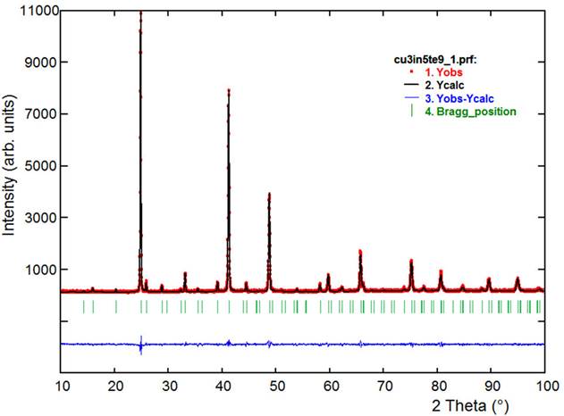
Figure 1 Final Rietveld refinement plot for Cu3In5◻Te9. The lower trace is the difference curve between observed and calculated patterns. The Bragg reflections are indicated by vertical bars.
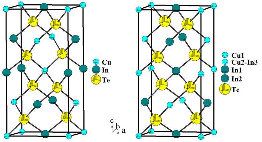
Figure 2 Unit cell diagram for the chalcopyrite CuInTe2 (I42d) compared with the new P-chalcopyrite Cu3In5◻Te9 (P42c).
This behavior was also observed in CuFeInSe3 [25], with composition I-II-III-VI3, and in the OVC’s Cu3In7Se12 [26] and Cu3In7Te12 [27,28] with composition I3-III7-◻2-VI12. The tetrahedra containing the Cu atoms [mean Te…Te distance 4.20(1) Å] are lightly smaller than those containing the In2 atoms [mean Te…Te distance 4.27(1) Å], In1 atoms [mean Te…Te distance 4.44(1) Å] and (Cu2-In3) [mean Te…Te distance 4.61(1) Å], respectively. The Cu-Te [2.570(6) Å] and In-Te [2.666(7) Å] average bond distances compare quite well with those observed in other adamantine structure compounds such as CuInTe2 [16], CuTa2InTe4 [29], Cu3NbTe4 [30], CuCo2InTe4 and CuNi2InTe4 [31], Cu3In7Te12 [27,28], AgIn5Te8 [32] and AgInTe2 [33].
4. Conclusions
The crystal structure solution of the semiconductor compound Cu3In5Te9 (or Cu3In5◻Te9) was resolved in the space group P 2c by the evaluation of different models derived from the ◻-Cu0.39In1.2Se2 structure against the powder X-ray diffraction data, using the Rietveld method. This compound crystallizes in a P-chalcopyrite structure, and is the first structural report on a member of the I3-III5-◻-VI9 semiconductor composition.

