Research
A method to obtain orientation curves in Euler space for a seccond diffraction process in polycrystals
J. Palacios Gómez1
R.S. Salat Figols1
T. Kryshtab1
1Escuela Superior de Física y Matemáticas, Instituto Politécnico Nacional, Ciudad de México. México
Abstract
A method is presented to obtain the orientation curve in the Eulerian space, of crystallites which diffract in one point of a Debye-Scherer ring in a second diffraction process. The incident beam is therefore the reflected beam of a previous diffraction process, and the sample has a general orientation for a pole figure measurement, given as usual by two angles, χ around the sample 𝑌 axis, and 𝜑 around the sample normal. Two solutions are found for all secondary reflections. The method proposed here was outlined somewhere else for the measurement of pole figures by neutron diffraction, and here important improvements are made, especially regarding the mathematical methods.
Keywords: X-ray diffraction; texture; extinction
PACS: 61.05.cp
1. Introduction
Multiple scattering is generally not considered in X-ray or neutron diffraction from polycrystals, due to the negligibly low intensity expected from this effect; however, measurements of pole figures show significant differences in many cases when density maxima from first and second orders are compared to each other, indicating that primary or secondary extinction could be present1-3. If secondary extinction is dominant, a way to verify it could be to test if the curve of crystallite orientations for the second diffraction coincides with high populated zones of the Orientation Distribution Function (ODF) of the textured sample. As well known of diffraction from polycrystals, the intensity at a point of a Debye-Scherrer ring hkl, or the pole density at a point on the pole figure, is caused by the superposition of the intensities diffracted by many crystallites, all of which satisfy the Bragg condition for the planes (hkl). This crystallites have in common the normal direction of planes (hkl), but differ otherwise in orientation so that their orientations lie along a curve in the Eulerian space, i.e. the pole figure is a projection of pole densities along a path through the ODF corresponding to a 2 π-rotation around the diffraction vector 5. This happens also for the second diffraction process, being the incident vector orientation the only difference, so that the diffracting crystallites lie also along a curve in the Eulerian space. So the aim of this work is to evaluate the orientation curves for the main reflections for a secondary diffraction, and for a general sample orientation given by the conventional angles (χ,φ). This scope was proposed by Palacios et al., 1, however, the mathematical method used allowed only one solution of the main equation expressing the Laue condition for a second reflection (Eq. (7) of 1), and no modifications were made for especial cases where no solution (for example reflections where h=k=0) could be obtained. This work aims to solve this deficiencies, and to improve solutions. For the sake of completeness, the figures and the background of the main equation are repeated here.
2. The method
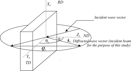
Let k0 be the wave vector of an X-ray photon, which has already been diffracted by planes (h0k0l0). If θ0 is the Bragg angle of the first diffraction, and k=2π/λ with λ the radiation wave length, this is in the sample reference system
k0=k(0,cosθ0,sinθ0).
(1)
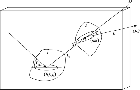
To determine possible secondary diffraction processes this wave can produce in the polycrystalline sample, the orientation curve of crystallites contributing to the intensity registered at a general point of a Debye-Scherrer ring produced by diffraction from plane (hkl) is to be calculated. Figure 1 shows the primary diffraction layout, and Fig. 2 shows the sequence of both diffraction processes.
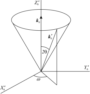
It is convenient to rotate the reference system an angle α around X0, to make k0 to coincide with the Z axis. Let ω be an angle characterizing a point of a Debye-Scherrer ring, as shown in Fig. 3. The wave vector of the second diffracted wave is then in the new reference system
k'0=k(sin2θcosω,sin2θsinω,cos2θ).And expressed in the sample reference system, it is
k0'=k(sin2θ cosω,sinθ0 sin2θ sinω+cosθ0 cos2θ,-cosθ0 sin2θ sinω+sinθ0 cos2θ)
(2)
If Q0≡k'0-k0, then
Q0=k(qx0,qy0,qz0)
(3)
with
qx0=sin2θcosωqy0=2sinθ(sinθ0cosθsinω-cosθ0sinθ)qz0=-2sinθ(cosθ0cosθsinω+sinθ0sinθ)
(4)
where the superindex 0 indicates that the sample is in its initial orientation (0,0).
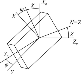
Q0 in terms of the pole figure angles (χ,φ)
As in a measure of a pole figure, let the sample be rotated an angle χ around the Y axis (TD), followed by a rotation of an angle φ around the normal direction of the sample. Figure 4 shows the sample in this general orientation for the measurement of a point (χ,φ) of the pole figure. Q is the vector Q0 as seen by the sample in its new orientation after both rotations:
Q≡*20cQxQyQz=k*20ccosχcosφqx0+sinφqy0-sinχcosφqz0-cosχsinφqx0+cosφqy0+sinχsinφqz0sinχqx0+cosχqz0=k*20cqxqyqz
(5)
Crystallites for which Q satisfies Laue conditions
Let hkl be a particular reflection, and C a crystallite such that the vector Q satisfies Laue conditions for a certain reciprocal vector Ghkl. The vector Q as seen by C is
QC=Mφ1ϕφ2Q
(6)
where φ1, ϕ, φ2 are the Eulerian angles of the crystallite; i.e. those which bring the sample system to coincidence with C, and Mφ1ϕφ2 is the rotation matrix 6 (Eq. (2.50)):
Mφ1ϕφ2=*20ccosφ1cosφ2-sinφ1sinφ2cosϕsinφ1cosφ2+cosφ1sinφ2cosϕsinφ2sinϕ-cosφ1sinφ2-sinφ1cosφ2cosϕ-sinφ1sinφ2+cosφ1cosφ2cosϕcosφ2sinϕsinφ1sinϕ-cosφ1sinϕcosϕ
(7)
Then
QC=Ghkl
(8)
where Ghkl=hA+kB+lC is the reciprocal lattice vector corresponding to the reflection hkl. For a cubic system with lattice constant a:
GGhkl=2πa(hι+kj+lk)
(9)
where í, j and k^ are unit vectors of C.
After applying matrix Mφ1ϕφ2 to (6), with k2π/λ, and from (8) and (9), it follows
Asinφ2+Bcosφ2=λah-Bsinφ2+Acosφ2=λakCsinϕ+Dcosϕ=λal
(10a,b,c)
where
Aφ,ϕ=cosφ1 cosϕqy-sinφ1 cosϕqx+sinϕqz Bφ1=cosφ1qx+sinφ1qy Cφ1= qx sinφ1- qy cosφ1
(11a,b,c)
Some properties of coefficients A, B, C andD
From (11a) and (11c) it can be readily be seen that
A=-Ccosϕ+Dsinϕ
(12a)
Multiplying (10a) by sinφ2, (12b) by cosφ2, and adding
A=λa(hsinφ2+kcosφ2)
(12b)
and similarly for 𝐵
B=λa(hcosφ2-kcosφ2)
(12c)
It follows then
A2+B2=(λa)2(h2+k2).
(12d)
Also, from (11b) and (11c)
B2+C2=qx2+qy2And with (11d)
B2+C2+D2=qx2+qy2+qz2
(12e)
Since rotations do not change the magnitude of vectors
Q2=Qc2from which, using (5), (8), and (9)
qx2+qy2+qz2=λa2(h2+k2+l2)Using (12e), this equation gives
C2+D2-λa2l2=λa2(h2+k2)B2and using (12d),
[C2+D2-λa2l2=A2]
Solution of Equations (10)
Equations (10) are not independent, and the way adopted here to solve them is as follows:
φ1From (11b) and (11c), B(φ1) and C(φ1) are obtained, and (10c) is solved for ϕ.
From (10a) and (10b) φ2 is obtained.
To solve (10c) the following method is proposed for a general equation with coefficients a, b and c:
asinγ+bcosγ=c
(13)
Let
sinγ=eiγ-e-iγ2icosγ=eiγ+e-iγ2Equation (13) is then:
eiγa2i+b2+e-iγ-a2i+b2=cMultiplying by 2ieiγ
e2iγ(a+ib)-a+bi=2iceiγe2iγ(a+ib)-2iceiγ+(-a+bi)=0This is a quadratic equation in eiγ whose solutions, after multiplying by a-ib, and separating real and imaginary parts are
e2ιγ=cd±aa2+b2-c2a2+b2+iac∓ba2+b2-c2a2+b2from which
cosγ=cd±aa2+b2-c2a2+b2sinγ=ac∓ba2+b2-c2a2+b2
(14a,b)
Applying this to (10c) with a=C, b=D, γ=ϕ and c=(λ/a)l
cosϕ=λalD±CC2+D2-λa2l2C2+D2sinϕ=Cλal∓DC2+D2-λa2l2C2+D2From (12f) these equations become
cosϕ=λalD±C|A|C2+D2sinϕ=λalC∓D|A|C2+D2
(15a,b)
Let ϕ1,2 be the angles obtained for upper and lower signs respectively. A is then obtained from (12a), and (15a) and (15b):
A=-Ccosϕ+Dsinϕ=-CλalD±CAC2+D2+DλalD±CAC2+D2=∓(A)i.e
A(ϕ1,2)=∓|A|
(16)
This means A(ϕ1)<0, and A(ϕ2)>0.
Equations (10a) and (10b) form a system of two linear equations whose solution is
sinφ2=λahA-kBA2+B2cosφ2=λakA-hBA2+B2Using (12d), expressing A=A(ϕ), and applying (16)
sinφ21=aλ-h|A|-kBh2+k2cosφ21=aλhB-|A|kh2+k2sinφ22=aλh|A|-B|k|h2+k2cosφ22=aλhB+|A|kh2+k2
(17a,b,c,d)
with the condition
h2+k2>0
Especial case h=k=0
If h=k=0 then, from (12b) B=0, and from (11b)
tanφ1=-qxqyAnd from (12a) A=0, i.e. from (11a)
tanϕ=sinφ1qx-cosφ1qyqzWhich, using (18a) can be written
ϕ=tan1{-1qzqx2+qy2}
(18b)
Which means that for this case there is only one value for φ1 and one for ϕ, and φ2 can take any value. The orientation curve is a straight line, but its value depends of qx, qy and qz.
Equation (18a) has no solution if qx=qy=0. This can come from (5) for the especial case χ=φ=0, and qx0=qy0=0, which corresponds to the symmetrical sample orientation, and it can readily be seen that ϕ=0 and φ1+φ2 can take any value.
Total of solutions
Except for the especial case h=k=0, following solutions gi,j are obtained:
g1=(φ1,ϕ1,ϕ21)g2=(φ1,ϕ2,ϕ21)
(19)
These are two curves if h2+k2>0, or a straight line along φ2 if h=k=0.
3. The computer program
A program in Dev C ++ has been written, as follows:
Primary data are given: Pole figure affected, i.e. (h0k0l0), secondary reflection (hkl), point ω of the Debye-Scherrer ring of secondary reflection, lattice constant of sample a, sample orientation (χ,φ), and wavelength λ. From these data, Bragg angles θ0 and θ for primary and secondary reflections respectively are calculated. Initial φ1 and an increment Δφ1 are also given.
qx0qy0qz0qxqyqzBϕφ2The especial cases h=k=0 is solved from Eqs. (18).
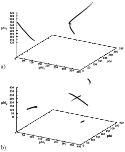
4. Results
Figures 5 and 6 show some results for a silver sample using copper radiation. Curves are usually closed but they appear fragmentary when some angle reaches the 2π value. Particularly not every value of φ1 has a solution. Two curves result for each sample orientation, and for first and second reflections since every orientation of the sample is represented by two sets of Eulerian angles (φ,φ,φ) (6, Eq. (2.4)).
5. Conclusions
A method has been developed to determine the orientation curves of crystallites able to produce a second diffraction of an incident photon. Calculations require only modest computer capabilities, and they could be applied in future work to determine the integrated intensity of the whole Debye-Scherrer rings, as a measure to evaluate the intensity loss due to a possible effect of secondary extinction.
The aim of this work is thus fulfilled; however, to know if these curves pass through high pole density zones, further calculations will be necessary since on the one hand, due to symmetric properties of the samples, only a part of this cube of side length 2𝜋 will be sufficient, and on the other hand, every curve should be first subdivided in segments of equal length. Both aspects require careful operations, and for the moment they are beyond the scope of this work.
Acknowledgments
Helpful discussions with our colleague Francisco Cruz Gandarilla are kindly acknowledged. Also, one of us, J. Palacios, wants to thank the Instituto Politécnico Nacional, for supporting this work with a sabbatical leave.
REFERENCES
1. J. Palacios Gómez, T. Kryshtab, C.A. Vega Rasgado, Z. Kristallogr,.. Proc. 1 (2011) 119-124.
[ Links ]
2. A. Mücklich, and P. Klimanek,.. Kryst. Res. Technol 23 (1988) K105-108.
[ Links ]
3. J. Palacios Gómez, T. Kryshtab, C.A. Vega Rasgado, Z. Kristallogr,.. Proc. 1 (2011) 119-124.
[ Links ]
4. A. Cadena Arenas, T. Kryshtab, J. Palacios Gómez, A. Kryvko Ingeniería, Investigación y Tecnología, XV (21) (2014).
[ Links ]
5. U.F. Cocks, C.N. Tomé and H.R. Wenk, Texture and Anisotropy-Preferred Orientations in Polycrystals and their Effect on Materials Properties, Cambridge University Press (1998), Cambridge, U.K. (pages 104-105).
[ Links ]
6. H.J. Bunge, Texture Analysis in Materials Science, (Butterworths 1982).
[ Links ]


 text new page (beta)
 English (pdf)
 Article in xml format
 Article references
 Send this article by e-mail
 Cited by SciELO
  Similars in
SciELO
Similars in
SciELO 
 Permalink