


 nueva página del texto (beta)
 Inglés (pdf)
 Artículo en XML
 Referencias del artículo
 Enviar artículo por email
 Citado por SciELO
  Similares en
SciELO
Similares en
SciELO 
 Permalink
1. Introduction
In 2009 members of the Topical Network on High-Energy Physics came to the conclusion that it was necessary to start the training of specialized human resources in particle accelerators. With the help of the Division of Particles and Fields of the Mexican Physics Society (DPyC-SMF) 1 a program was initiated whereby students were sent to different laboratories to obtain knowledge and experience about particle accelerators; consequently, from this endeavor the Mexican Particle Accelerator Community (CMAP) was created. From this project another set of collaborations in this field between Mexican universities and international laboratories such as CERN 2-6, Jefferson Lab 7, Berkeley Lab, and KEK/JPARC 8 were created, where state-of-the-art research has been conducted by the CMAP members.
There are small electrostatic accelerators in Mexico 9,10, however, in terms of Radio Frequency (RF) accelerators there are not institutions or groups dedicated to the research and development of such systems.
In this paper CMAP presents a proposal for an electron Linear Accelerator (eLINAC) 11. The design is competitive with other electron linacs 12 in terms of emittance growth and acceleration gradients and it can provide two operation modes: electron and gamma radiation beams. With these two configurations, it will cover a wide range of applications from basic research to industrial and medical applications. The eLINAC is an inter-institutional collaboration as it requires knowledge that can not been performed by single individuals. The main goals of the project are to improve the technology development of the country and to boost the accelerator field along with the intensification of the training efforts of highly qualified scientists and engineers.
The lattice design of the eLINAC is shown in Fig. 1. It consists of three beam lines of 10, 60 and 100 MeV, the first two beam lines are composed of three 2 m focusing defocussing cells (FODO), each FODO is composed of two quadrupoles and the final beam line has only one FODO cell. Two RF cavities are between among the three beam lines. In order prevent beam losses it is necessary to keep a reasonable beam size along the line, a 60◦ phase advance per FODO cell was selected, thereby minimizing the maximum value of the β functions (25 mm) to reduce the emittance growth the quadrupole apertures above 10 cm to avoid the non linear fields. The magnetic gradients for the three pairs of quadrupoles from the source to end of the beam line are: 0.09 T/m for the 10 MeV Line, 0.5 T/m for 60 MeV and 0.9 T/m in the 100 MeV, respectively.
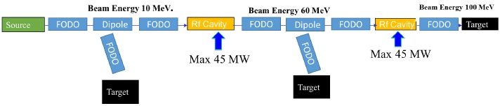
The beam pipe has been chosen to have a 30 mm aperture, limiting the maximum 1 r.m.s. beam size to 5 mm due the particles allocated after 3 σ which will hit the beam pipe walls. The improvements on the design involve the addition of a solenoid magnet at the beginning of the eLINAC and incorporating a dipole magnet to bend the beam between the two FODOs to a new line (Fig. 1), the dipole will be employed to produce the synchrotron radiation and steering the beam to the target, the new line includes an extra FODO to match the beam to the users needs. Table I lists the main machine and beam parameters 12.
Table I eLINAC basic parameters.
| Parameter | Value | Units |
|---|---|---|
| Normalized emittance | 1.0 | mm.mrad. 1 r.m.s. |
| Energy | 100 | MeV |
| RF cavities | 2 | |
| RF frequency | 2996 | MHz |
| Repetition rate | 1 | kHz |
| Beam current | 400 | mA |
| FODO cells per line | 3. 3, 1 | |
| Magnetic gradient 10 MeV | 0.09 | T/m |
| Magnetic gradient 60 MeV | 0.5 | T/m |
| Magnetic gradient 100 MeV | 0.9 | T/M |
2. RF SOURCE
The electron source is a normal conducting RF source running in the S-band (2998 MHz) capable of delivering a beam energy of up to 10 MeV with a beam current ranging from 10 to 400 mA. The importance of reaching these levels of current and energy from the first beam line of the accelerator chain resides in the industrial applications that can be explored within these parameters. To enable a more stable acceleration a DC electrode will accelerate the electrons to 100 keV to inject the beam into the RF cavity. A biased grid will control the timing of the electron emission in the thermionic cathode to match the RF buckets from the source and avoid the beam injection in the wrong phase (ϕ) and the longitudinal emittance (ϵϕ) growth. The longitudinal emittance is given by
where ωrf is the RF frequency and ∆E the total gain energy. A technique such as controlled space charge compensation, will be used to minimize the emittance growth during the beam formation and provide a high-quality beam, reducing the Coulomb repulsion in the DC region of the beam.
2.1 Rf Cavity simulations
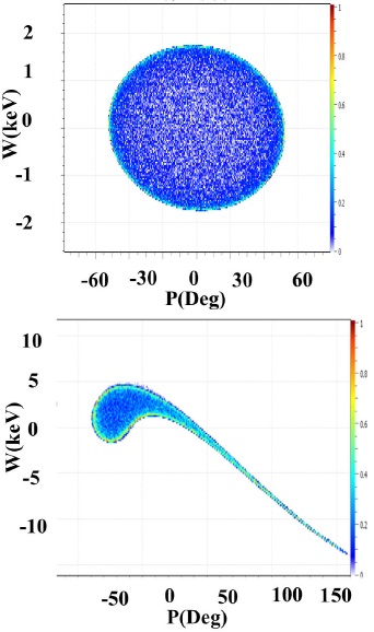
To study the RF cavity acceptance 13, simulations were performed using the code POISSON 14 and TRAVEL 15. A beam with an energy of 100 keV, 10% energy dispersion and longitudinal dispersion of 40±, were assumed. The beam was accelerated within the first three cells of the cavity to study the longitudinal acceptance. Figure 2 shows the results of how the beam particles in the correct phase are accelerated from 100 keV (the plot are centered in the plot to the mean energy W in keV) to 280 keV and how the cavity can only capture in the longitudinal phase space within -40° to 0° where the optimum acceleration phase has been matched to -40° in the cavity. This acceptance corresponds to a 70% transmission assisting to decrease the beam emittance in the lower energy region.
3. Beam Lines
The eLINAC is composed of three beam lines that either match the beam to the next acceleration section, or bend it to the user’s application areas at the different energies 16 and beam sizes. Furthermore the lines need to be implemented in such way that they keep the emittance as constant as possible before entering the next RF acceleration cavity.
The first iteration of the beam line design was made using the code MAD-X 17 solving the Hill’s equation
where k(z) denotes the magnetic gradients along the beam path in z. Solving this system for the desired beam constrains at the start and end of the each line, provides the first estimation of the necessary quadrupole strength. As a second step, the defocussing action of space charge (K0) and the emittance (ϵ) pressure are included in the beam transport by solving the envelope equation,
using the code TRAVEL, where the term K0 is the space charge term known as the perveance and its form will depends of the beam input distribution.
3.1. 10 MeV line
Once the beam is accelerated in the source, it travels into a 2m-long transport system composed of four quadrupoles that will reach a maximum field of 0.3 T in the tip of the poles to ensure enough focus strength; two corrector magnets will be included. There is a 0.5 m distance between the two pairs of quadrupoles that will allow to allocate beam diagnostics, and a dipole to send the beam directly into the user’s stations. After the dipole, a user beam line will be set (for example, for gamma beam generation via the collision of the beam with a target), where an extra FODO lattice with the same parameters controls the beam size.
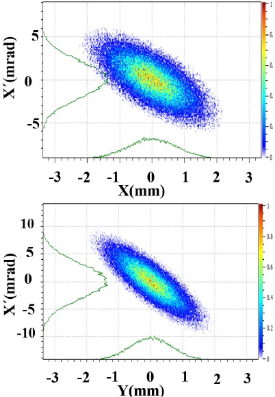
As a worst-case scenario, a strongly divergent beam in the two transversal planes was simulated. The horizontal phase space (X, X′ = Px /P) at the entrance and exit of the FODO is presented in Fig. 3 where X′ is the beam particle momentum divergence respect to the reference particle traveling in the center of the eLINAC, and X is the distance respect to the beam line center. The emittance was assumed to be four times the baseline goal, making the 1 r.m.s beam size at the entrance of the line to be 3 mm. This corresponds to the expected beam size at the exit of the RF cavities.
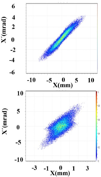
Figure 3 The horizontal phase space distribution in the FODO cell: input (left) and output (right) beam.
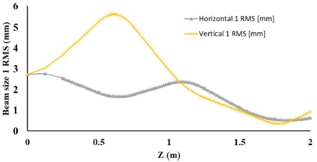
Due to the initial beam divergence, the maximum beam size is 6 mm after the first quadrupole, setting a minimum beam pipe radius of 20 mm to ensure full transmission along the line. Figure 4 shows the beam size evolution in both planes along the beam line and the beam focusing at the end of the line to match it to the next cavity with a beam size below 1 mm.
3.2. 60 MeV line
Once the beam is matched to the second RF cavity, it is accelerated to a maximum of 60 MeV. Then, the beam arrives to the second transport system similar to the previous one, with the goal of matching the beam to the third RF cavity. At this section, it is necessary to increase the quadrupole magnetic strength, due to the higher beam energy, if the constrain of the same beam line length is imposed. As in the previous section the input beam parameters assume the highly divergent beam, after a series of simulations the best matching conditions show a maximum beam size of 6 mm, setting the necessary beam pipe radius at 20 mm. From the equation.
where E is the beam electric field and γ is the relativistic factor, an advantage on this line is clear: at higher energy the space charge repulsion decreases. Studies show that the matching conditions can be ensured up to a 1 A beam current leaving the line ready to future upgrades (see Fig. 5).
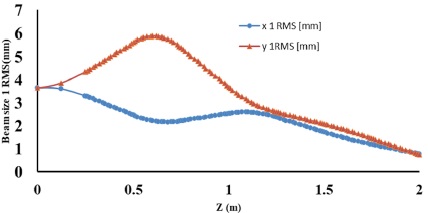
Figure 5 The horizontal phase space distribution in the FODO cell: input (left) and output (right) beam.
Once the beam is matched to the next cavity the transverse beam phase space profiles in Fig. 6 shows a symmetry in both planes, permitting the cylindrical match necessary for the correct injection into the acceleration section.
4. Quadrupole magnet Study
Quadrupoles magnetic, thermal, and mechanical studies have been conducted using the code COMSOL 18. For the quadrupoles, the gradient (5 T/m) and geometric requirement (2 cm bore radius), and a standard type geometry, have been selected. The quadrupole design allows the poles to be inserted into the yoke once the winding is complete, maximizing inter-pole space and simplifying assembly.
Each pole has seven layers, each one with 18 turns of copper wire (2.053 mm in diameter), and with an operational current set at 6.6 A. A safety factor of 2 A in the recommended values for the operational current has been used. This provision has a positive impact on the thermal model by reducing the power dissipated per wire (P = I2ρLA−2), and creates the possibility for a gradient upgrade if necessary. Figure 7 shows a quarter of the quadrupole design.
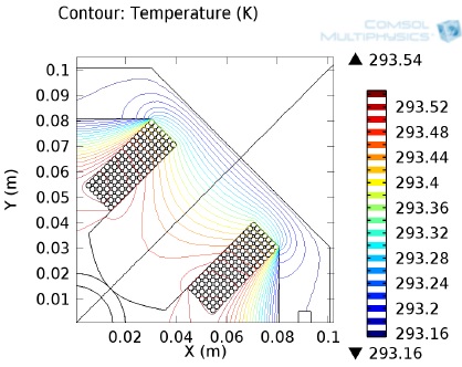
Figure 7 A quarter section of the quadrupole. The Joule-lenz heating model was used to estimate operational temperature at full field.
To assess the quality of the quadrupole design, it is useful to describe the magnetic field inside the aperture of the magnet in terms of the harmonic coefficients. The magnetic field components Bx and By produced by an accelerator magnet can be specified by the multipole expansion,
where Bro is the magnitude of the field due to the fundamental harmonic at the reference radius Rr (1.5 cm for this calculations) on the midplane, bn and an are the normal and skew multipoles 19. For the 5 T/m gradient, the allowed higher order multipoles b5, b9 and b1320 are kept below 1 unit, and field uniformity within 1 %. Modifications of the design could improve field uniformity if required. Table II shows the most relevant parameters for the quadrupoles design.
Table II Quadrupole design parameters.
| Parameter | Value | Units |
|---|---|---|
| Input current | 6.6 | A |
| Bore radius | 0.22 | m |
| Cu-wired OD | 2.025 | mm |
| Turns | 126 | |
| K | 5 | T |
| K uniformity | < 1 | % |
| Forces | 1.2 | N (pole tip) |
| Top | 293.54 | K |
| 5 G Line | 77 | mm (B0 along Z Axis) |
| 15 G Line | 50 | mm (B0 along Z Axis) |
| 50 G Line | N/A | N (pole tip) |
The geometry was optimized using an iterative shimming strategy at the ends of the hyperbola pole profile. The Joulelenz 21 power dissipation model was used to estimate operational temperature of the quadrupole at full field. The model estimates an operational temperature of 293 K at full field, which allows air cooling. A mechanical model was computed to understand the distribution of Lorentz forces along the base of the pole, with the aim to estimate the net displacement of the pole in the iron yoke at full field and the way this affects the multipole content and field uniformity. A preliminary model estimates an outward force of 1.2 N towards the base of the pole, as can be seen in Fig. 8.
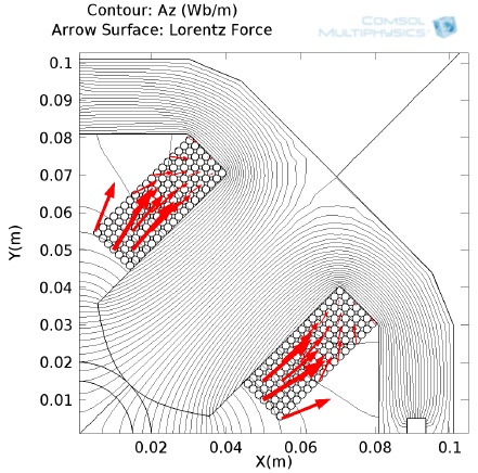
Figure 8 Quarter section of the quadrupole with isoline for Lorentz force calculation on the base of the pole.
The iron yoke fully encloses the magnetic field at the body of the quadrupole, adding no contribution to the fringe field. At the end of the quadrupole, there is a small region in which the winding around the poles is not covered, this region adds a contribution to the fringe field that extends out of the quadrupole. This intrinsic non-lineal fall-off behavior of the magnetic field with the distances may result in interference with other instruments. According to the International Commission on Non-Ionizing Radiation (ICNIRP), prudent practice requires posting warning at the 5-G line, and limiting access to areas with more than 10 to 20 G to knowledgeable staff 22. The 5, 20 and 50 Gauss line were computed and values are shown in Table II.
In order to determine the best winding technique for the quadrupole, two mock-up prototypes have been printed in 3D at full scale, and a third will be built on aluminum. Three teams are working on the winding strategy, at Texas A&M University, another at the University of Sinaloa, and the third at the University of Guanajuato. For the Aluminum prototype a special tooling for winding is being developed and the manufacturing is programmed at the end of 2017. The material choice for the iron yoke is key to the quadrupoles performance. To determine the best cost-effective material, field calculations will be re-computed as different materials are selected for the iron yoke. The current candidates are: Pure Iron, steel 1006, steel 1008, steel 1010, steel 1018, steel 1020, steel 1030, Iron 1018, Cast Iron, Cast Steel, Magnet steel, and SS416. The material selection will be based on readiness of machinability, low impact on field quality and lowest production cost.
5. Beam Losses
Optics simulations showed not significant beam losses for the beam line simulations in both transverse planes. This is expected since the maximum r.m.s. beam size is around 6 mm in the vertical plane for an electron beam with Gaussian profile when the pipe aperture is 20 mm. In addition, cases for beam loss cases when one of the quadrupoles is off were simulated. The beam power loss distribution along the line of 10 and 60 MeV for the different failures in quadrupoles and increasing the beam size are shown in Fig. 9.
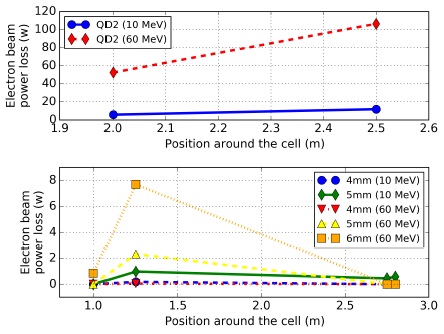
Figure 9 Beam power loss distribution along the cell for the quadrupoles errors (top) and the input beam size increasing (bottom).
For the radiation protection of personnel and environment, the biological dose outside of the shielding area must be in the range of 0.5 to 2.5 μSv/h. Using the results of the study for a 100 MeV eLINAC with a beam power of 100 kW (100 times more beam power than our proposal) 23, an estimation of the shielding for similar configuration (1.2 m distance from the beam line to the wall) is 0.5 m thickness with a concrete density of 4.8 g/cm3.
6. Conclusions
The design of an RF electron eLINAC including the transverse and longitudinal beam dynamics has been presented. The design of the quadrupoles has been studied and production of prototypes are envisioned in the near future. No significant beam losses are found for normal operation mode; only in failure mode losses can be observed.
The beginning of this project has been possible thanks to the effort and experience of the CMAP members. The community is ready to propose and lead the design, construction, and commissioning of particle accelerator projects in Mexico, example of which is the current eLINAC project presented here. Mexico has assembled a critical mass of accelerator physicists and engineers capable of building and operating particle accelerators. In addition, there are many possible users for this type of development in the country, such as the synchrotron radiation, material science and nuclear communities that can use the eLINAC as a tool to boost their scientific research.
The eLINAC that will provide two operational modes: electron and gamma radiation beams. With these two modes, it can cover a wide range of applications from industrial, medical and basic research applications. This project has the potential of significantly improving the technological development of the country, and to boost this area along with the training of highly qualified scientists and engineers. In addition, the machine can serve as the first accelerating chain to a more complex machine.

