


 nueva página del texto (beta)
 Inglés (pdf)
 Artículo en XML
 Referencias del artículo
 Enviar artículo por email
 Citado por SciELO
  Similares en
SciELO
Similares en
SciELO 
 Permalink
1. Introduction
Polythiophene derivatives, especially poly(3-alkylthiophenes) (P3AT), are one of the most studied polymers for photoelectronic applications because of their relative stability in air and processability in solution. Poly(3-hexylthiophene) (P3HT) and poly(3-octylthiophene) (P3OT) are of particular interest due to their p-type semiconducting behavior with an electron affinity of
On the other hand, inorganic semiconductor nanoparticles (NPs) have been shown different electronic, photoconductive and luminescent properties compared to ther bulk materials2,3. For example, NPs show better charge transfer speeds when chemically bound within an organic polymer matrix. This has enabled their use as acceptors in hybrid solar cell. Hybrid nanocomposites, formed by conducting polymer and semiconductor inorganic nanocrystals (NCs), have been used as volumetric heterojunction structures (BHJ) for solar cell applications and attracted great attention because of the complementary light absorption of each component as well as improved charge carrier collections4. A facile method enabling the engineering of the properties for hybrid nanocomposites by simply adjusting the size of nanoparticles and the homogeneous dispersion of the inorganic phase into the organic phase is a key to improve the performance of photovoltaic devices. Among the materials used in hybrid systems poly(3-alkylthiophenes) with cadmium selenide (CdSe) and cadmium sulfide (CdS), has been extensively studied5-11. Interest in NPs for applications in inorganic/organic photovoltaic devices increased with the results of CdSe NPs and P3HT system as the active layer in BHJ devices reported by Huynh et al.5. A common method to prepare such hybrids is to mix inorganic nanoparticles with the conjugated polymer in a common solvent8. For example, in Ref. 5, CdSe nanorods were co-dissolved with P3HT in a mixture of pyridine and chloroform and then deposited by spin coating to form a uniform film consisting of CdSe nanorods dispersed in the polymer. It was shown the CdSe nanorods dispersed in P3HT could be oriented to improve charge transport in the resulting photovoltaic device.
The conventional method to prepare hybrid materials involves the use of some surfactant to help the dispersion of NPs in the polymer. This helps to improve the homogeneity of the NPs distribution in the polymer matrix. However, the surfactant molecules might form an insulating interface between the polymer and the NPs resulting in a degraded charge transport5,12-14. Furthermore, mixing pyridine-capped NPs and polymer requires the use of a co-solvent, which can adversely affect NPs solubility and polymer chain orientation. These drawbacks considerably reduce the efficiency of the solar cells. The use of surfactants can be eliminated by either a) developing NPs-conjugated polymer without the use of surfactants and /or ligands, b) directly growing NPs in a polymer solution without surfactants or ligands15,16, or c) incorporating the NPs during the synthesis of the polymer without surfactants4. Demonstration of methods (b) and (c) is limited, especially the last one. Synthesizing the NPs directly in a conducting polymer (b), or synthesizing the conducting polymer in presence of NPs (c) eliminates the need for additional mixing or blending and results in a technique to synthesize nanocomposite materials suitable for optoelectronic applications. Therefore, the development of hybrid materials (Organic/Inorganic) without the use of surfactants and/or ligands has become technically challenging because of its possible benefit for photovoltaic device applications.
Till now only few reports exist for in-situ synthesis of semiconductor nanocrystals in a conducting polymer. For example, in 2004, an in situ synthetic method was used to synthesize PbS nano-crystals/MEH-PPV composites. The authors showed that the polymer chains can sterically stabilize nanocrystal growth in the solution16,17. Liao et al.9,18, synthesized CdS single-crystal nanorods directly in the presence of conjugated P3HT, where the polymer was acting as a molecular template to manipulate the CdS nanocrystals and, at the same time, as an efficient charge conductor. A photovoltaic device consisting of CdS nanorods with aspect ratio of ca. 16 and P3HT was assembled and showed a power conversion efficiency of 2.9% under air mass (AM) 1.5. Dayal et al.19, showed the successful synthesis of CdSe nanoparticles in a P3HT-containing solution without the presence of any surfactant, and showed that photo -induced charge separation occurs at the nanoparticle -polymer interface, which is desired for high efficiency photovoltaic solar cells19. Sonar et al.20, synthesized CdS and CdSe nanoparticles using a conducting P3HT matrix and determined that P3HT serves as an electrically, thermally and morphologically efficient matrix for the encapsulation of CdS and CdSe nanoparticles, especially for optical and optoelectronic applications. Agrawal et al.21, also synthesized CdS nanocrystals (NCs) in a P3HT matrix by decomposition of a single-molecule precursor. In that work, the final size and the optical band gap of the material depended on the concentration of P3HT and CdS and showed that the growth of CdS NPs in the presence of P3HT is hindered due to its steric effects.
In 2010, Lu et al. reported a novel configuration of hybrid solar cells using in-situ polymerization of P3HT on the surface of a TiO2 layer. The short-circuit current density and energy conversion efficiencies of the device with in-situ polymerized P3HT layer were 6X higher compared to that of device without the in-situ polymerized P3HT layer22. Subsequently in 2011, Ogurtsov et al. reported the synthesis and properties of new hybrid nanocomposites of poly(3-methylthiophene) (P3MT) and CdSe nanoparticles. The synthesis method was based on the chemical oxidative polymerization of 3-methylthiophene in the presence of CdSe nanoparticles4. This method allows covering the inorganic nanoparticles with a shell of P3MT. This core-shell structure may have an improved interaction between its components and, as a consequence, could facilitate the charge separation at the donor-acceptor interface. However, P3MT is insoluble in common solvents, whereas P3HT is more suitable for solution based solar cells. In-situ synthesis of P3HT in the presence of nanoparticles promises more and better incorporation of CdS in the polymer composite without the use of surfactants, which would give interesting application in photovoltaic devices23. In this work, P3HT/CdS nanocomposites were synthesized by in-situ oxidative polymerization of 3HT in presence of CdS nanoparticles. The results showed an improved interaction between the components of the composites. The effect of CdS nanoparticles in the synthesis of P3HT is studied by using microscopic and spectroscopic techniques, such as Scanning Electronic Microscopy (SEM), Atomic Force Microscopy (AFM), Transmission Electron Microscopy (TEM), Fourier Transform Infrared Spectroscopy (FTIR), UV/Vis spectroscopy and X-ray diffraction (XRD). A reaction mechanism is also proposed.
2. Materials and Method
2.1 Synthesis of CdS Nanoparticles
In the reported method, a 0.1 M solution of Na2S Fermont) and 0.1 M solution of cadmium acetate (Cd (OOCCH3)2⋅ 2H2O, Alfa Aesar, 99.999%) were prepared in methanol. The solution temperature was 25°C (room temperature). The cadmium ion solution was added slowly into the Na2S solution while stirring constantly. The solution changed from transparent to yellow, indicating that CdS was formed. The reaction time was 30 min. The CdS precipitates were washed by centrifugation at 4400 rpm for 3 min, 3 times with 50 mL of deionized water each time and 2 subsequent times with 50 mL of methanol. The resulting CdS NPs were dried at 50°C for 48 hours24.
2.2 Chemical synthesis of P3HT/CdS nanocomposites
For the synthesis of the P3HT/CdS nanocomposites a weight ratio of 1:2 for 3HT/CdS was used. The P3HT was obtained by direct oxidation of the 3HT monomer (Aldrich, 99%) using Ferric Chloride (Aldrich, FeCl3 97%) as oxidant at room temperature in an inert atmosphere25. In this reaction, 0.0167 mol of distilled 3-hexylthiophene dissolved in anhydrous CHCl3 is slowly added to FeCl3 (0.025 mol) and CdS nanoparticles dispersed in anhydrous CHCl 3 (molar ratio 3HT:FeCl3, 1:1.5). The reaction mixture was stirred at room temperature for 20 h. The product was precipitated in methanol, filtered and carefully washed with methanol, hydrochloric acid (10 vol. %), acetone, NH4OH (10 vol. %), ethylenediaminetetraacetic acid (EDTA, 1 vol. %) and distilled water. The resulting P3HT/CdS composite was then dried. For comparison, P3HT without CdS NPs was also synthesized following the same procedure.
P3HT/CdS and P3HT films were deposited on Corning glass substrates by spin-coating with a spin frequency of 3000 rpm using a solution with a concentration of 2 mg of polymer by ml solvent (chloroform). Before deposition, the solution was mixed using ultrasound for 20 min. Films were also deposited by drop-casting using the same solution.
2.3 Materials Characterization
The surface morphology of P3HT and P3HT/CdS nanocomposites films was studied by SEM (ZEISS SUPRA-40 SCANNING ELECTRON MICROSCOPE). TEM analysis was also carried out. For the TEM analysis, a drop of the CdS/P3HT composite was carefully transferred to a carbon-coated copper grid followed by evaporation of the chloroform solvent. A JEOL 2100F TEM was used for the analysis. AFM measurements of polymer films were carried out with a MFP 3D Bio AFM from Asylum research using the contact mode. FT-IR spectra of P3HT, CdS and P3HT/CdS composites were recorded on a Nicolet 6700 FTIR Spectrometer. Optical characterization of the P3HT and P3HT/CdS films was carried out in a USB4000 Fiber Optic Spectrometer in arrange of 300 to 1000 nm. X-ray diffraction analysis was carried out on a Rigaku MSC Ultima III X-ray diffractometer using a scanning rate of 1 deg/min in 2
3. Results and discussion
Figure 1 shows the SEM results of P3HT, CdS and P3HT/CdS composite. CdS nanoparticles synthesized at room temperature showed a homogeneous size and average particle size of about 6.8 nm (Fig. 1a). P3HT polymer was also uniform with no phase separation (Fig. 1b). SEM image of P3HT/CdS nanocomposite (Fig. 1c) showed that the CdS nanoparticles were uniformly distributed in P3HT polymer. Before starting the discussion about the incorporation of CdS nanoparticles in the polymer, we first compare the morphology of P3HT/CdS composites obtained by different sythesis procedures. In the cases of synthesizing the inorganic CdS compooud in the presence of P3HT, micrometer sized agglomerates and CdS nanocrystals were uniformly distributed at the film surface21. Furthermore, black spots of 1

TEM studies were performed on CdS nanoparticles and CdS/P3HT composite (Fig. 2), bright field TEM images (HRTEM), right size. The mean sizes of CdS nanoparticles are in the range of 5-10 nm and their shape is spherical, in agreement with the SEM results. From HR-TEM a plane distance was observed in which the 0.35 nm fringe spacing assigned to the (1 1 1) plane of cubic CdS. The contrast in Fig. 2 indicates the presence of CdS in the P3HT/CdS nanocomposite. The presence of sharper lattice fringes in the high-resolution image (right) shows good crystallinity of the
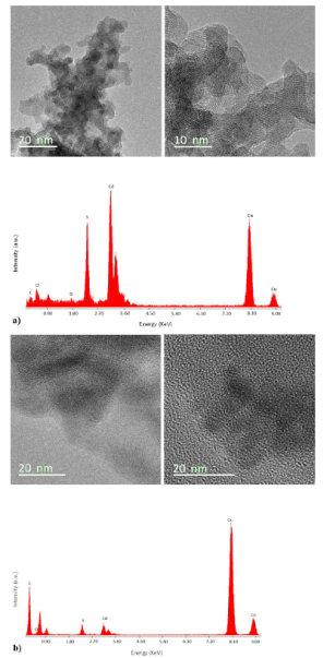
Figure 2 TEM images and TEM elemental analysis of a) CdS nanoparticles, b) P3HT/CdS nanocomposite. Right side, bright field TEM images.
P3HT/CdS. Figure 2b shows that CdS is incorporated in the nanocomposite. The CdS nanoparticles showed small clusters into P3HT because no stabilizer or agent were added to the CdS nanoparticles to prevent such agglomeration. The size of CdS nanocrystals into composite was around 10 nm. Similar HRTEM images were obtained by Sonar et al.20 for CdS/P3HT composite synthesized by in-situ synthesis of CdS in presence of P3HT, they also obtained size of CdS nanocrystals from 10-30 nm.
On the other hand, TEM elemental analysis (Energy Dispersion X-ray Spectroscopy, EDS) indicated that there is a loss of CdS during the washing process of the P3HT/CdS composite. According to EDS results, the intensities of the peaks corresponding to S and Cd were almost the same.
However, the atomic weight of CdS requires that the peak intensity of Cd should be about 3.5 times than the intensity of S. It means that the extra 2.5 S should come from the 3HT monomer units. Therefore, for every 2.5 3HT monomer units in P3HT there was approximately one CdS nanoparticle. The corresponding weight ratio (2.5:1 for 3HT/CdS) is higher than the initially used in the synthesis (1:2 for 3HT/CdS); the proportion of CdS regarding 3HT fell by one fifth in the composite product. Since CdS could be dissolved in acidic solution, the CdS nanoparticles on the surface of the polymeric membrane probably were dissolved and those CdS nanoparticles inside the polymeric membrane remained after washing by 10 vol.% HCl solution. As a result, the CdS concentration in the product was lower than the initial concentration in the polymerization reaction.
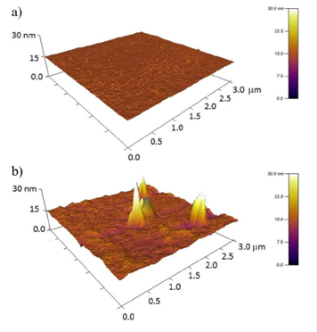
As evidenced from AFM topography for a 3 X 3
To further elucidate the role of CdS during the synthesis of the nanocomposite, Fig. 4 shows FTIR spectra for CdS, P3HT and P3HT/CdS samples in the frequency range of: 400-2000 cm-1 (Fig. 4a) and 2000-4000 cm-1 (Fig. 4b). The characteristic vibrational bands in the P3HT spectra were located at 3054 cm-1 (aromatic C-H stretching vibration of the thiophene ring), at 2955, 2925 and 2855 cm-1 (stretching C-H aliphatic, which have been assigned respectively to the asymmetric C-H stretching vibrations of -CH3 moieties, -CH2-- moieties, and symmetric C-H stretching vibration in -CH2- moieties)27. The two bands at 1460 and 1509 cm-1 (aromatic C=C stretching, symmetric and asymmetric) are characteristic of the 2,3,5-trisubstituted thiophene ring. The band at 1376 cm-1 corresponds to the methyl bending. The band at 1118 cm-1 to the C-S stretching, the band at 821 cm-1 to the aromatic C-H out-of plane vibration of a 2,3,5-trisubstituted ring and the band at 726 cm-1 to the rocking vibration of hexyl substituent methylene groups-(CH2)5-.)9,28-31. It is also observed in the FT-IR spectra of P3HT that the bands at 1242 cm-1 (𝜈(C-C) of acetone) and 1740 cm-1 (𝜈(C=O) correspond to acetone. This is likely due to insufficient drying of the samples after washing the products in acetone.
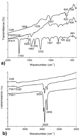
Figure 4 FTIR spectra in the frequency range: a) (400-2000 cm-1) and b) (2000-4000 cm-1) of P3HT, CdS and P3HT/CdS nanocomposite.
The FTIR spectrum of the CdS nanoparticles is also shown in Fig. 4. The vibration absorption peak of CdS, as reported in literature32,33 was observed at 410 cm-1. The strong absorption band observed at 640 cm-1 is probably due to the CdS stretch vibrations28,34. The CO symmetrical stretching at 1339 cm-1 and CO asymmetrical stretching at 1609 cm-1 are likely induced by trace amounts of acetate. The rest of peaks should also come from the impurities presented at the surface of CdS product.
The formation of P3HT-CdS nanocomposites was confirmed by the FTIR spectra as shown in Fig. 4. The intensity of peaks corresponding to C-S bond and aromatic C-H out-of plane stretching decreases and a shift of 5 cm-1 for the C-S characteristic band were observed in the P3HT/CdS composite. This indicates a reduction in the C-S bonding energy and suggests intermolecular interaction between S of polythiophene and Cd of the CdS nanoparticle. This interaction should be activated from the original C-S bond by the slight distortion of the electronic cloud of the C-S bond in the thiophene ring. The origin of such intermolecular interaction most likely results from a strong dipole-dipole interaction between the Cd and S atoms, prevailing along the backbone of the P3HT chain9. Agrawal et al. also reported that the intensity of the peaks corresponding to C-S bond and aromatic C-H out-of plane stretching decreases, which confirmed the chemical interaction between P3HT and CdS in the synthesis of CdS in presence of P3HT21. On the other hand, Liao et al.9 observed a slight shift of
The FTIR spectrum of the CdS/P3HT composite did not show any new bands. However, in the composite, the bands of acetone (1242 cm-1 and 1740 cm-1) disappeared, probably due to the fact that S atoms in the thiophene ring had already interacted with the CdS when the polymer was washed with acetone. This also confirmed the interaction between CdS and S of the thiophene ring. The absorption band at 1376 cm-1 is attributed to methyl bending band. Compared with pure P3HT, the intensity of the absorption band at 1376 cm-1 was lower when CdS was added to 3HT in the polymerization reaction. This also confirmed the absence of acetone, due to the loss of the CH3 group of the acetone. Finally, the wide band observed at 1009 cm-1 in the composite is due to the 1021 cm-1 of P3HT and 1007 cm-1 of CdS product, respectively. Also, the band at 620 cm-1 is broader
due to the superposition of the bands at 602 cm-1 (P3HT) and 640 cm-1 (CdS). All these findings demonstrated the interaction between CdS and S atom of thiophene ring.
Figure 5 shows the proposed mechanism for the growth of hybrid P3HT/CdS nanocomposites. The delocalized charges of CdS nanoparticles interact with the unpaired electrons in the sulfur of the 3HT monomers resulting in coupling of the two materials. Given the larger size of the CdS nanoparticles (
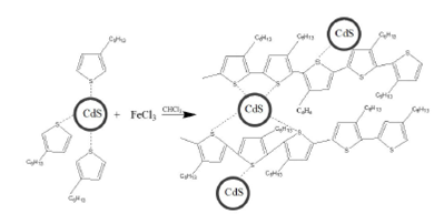
Figure 5 Schematic drawing for the proposed synthesis scheme of P3HT/CdS composite. The CdS crystals were assumed to be coupled with the unpaired electrons of S along the P3HT chain network. Proposed mechanism for the growth of the P3HT polymer.
UV-Vis spectra of regiorandom P3HT and P3HT-CdS nanocomposite of films obtaining by spin-coating on glass substrates are shown in Fig. 6. The inset in Fig. 6 shows the corresponding CdS absorption spectra. The absorption spectrum of regiorandom P3HT thin film shows strong absorption peak at 509 nm. This band is attributed to the excitation of electrons in the 𝜋-conjugated system36,37. In UV-Vis absorption spectra of CdS (inset Fig. 6), the maximum at

Figure 6 UV-Vis absorption spectra of CdS, P3HT and P3HT/CdS nanocomposite films obtained by spin-coating.
The absorption spectrum of the P3HT/CdS thin film obtaining by spin-coating (Fig. 6) shows
Liao et al.18 and Sonar et al.20 observed a small blue shift of
Thin films of P3HT/CdS nanocomposites obtained by spin-coating, showed a lower intensities of the
From the UV-Vis absorption it is clear that the P3HT/CdS composite had a higher ordering. This is further supported by the X-ray diffraction (XRD) analysis. Figure 7 shows the XRD pattern of CdS samples synthesized at 25°C for 24 h. The XRD peaks of CdS are very broad indicating very small size, consistent with TEM results. The XRD pattern exhibits prominent, broad peaks at 2

The semi crystalline nature of P3HT polymer can be seen in the 2
From the XRD results it also confirmed the in-situ formation of P3HT with CdS nanoparticles. The CdS nanoparticle signal was not yet visible because, as discussed above, the CdS concentration in the composite was small, and the number of account was low. These results agree with those reported in the synthesis of CdS nanocrystals directly in P3HT matrix with different CdS concentrations21. In that case, the crystalline reflections from the CdS nanoparticles became visible in CdS/P3HT composite from a concentration of 1:4 (P3HT:CdS). At concentrations of 1:1 and 1:2 these reflections were not clearly shown, just like what occurred to our composites, and only an increased intensity in the range 2
Ogurtsov et al. found that in the synthesis of P3MT/CdSe nanocomposites by the chemical oxidative polymerization of 3-methylthiophene in the presence of CdSe, the polymerization process is decelerated by CdSe nanoparticles. Specifically, the 3MT polymerization could be realized with a registered rate only at molar ratios of 3MT:FeCl3 = 1:5.34 and 1:13.3, being significantly higher the FeCl3 content than that suitable for the synthesis of individual P3MT (3MT:FeCl3 = 1:2.7). They assumed that the oxidation potential suppression and the existence of the minimal concentration of 3MT could be caused by the side reaction of CdSe oxidation by FeCl3. This side process resulted in the consumption of the oxidant and a partial dissolution of CdSe4. In our case, in the synthesis of P3HT/CdS nanocomposites by the chemical oxidative polymerization of 3-hexylthiophene in the presence of CdS, this phenomenon was not observed, we used the molar ratio 3HT:FeCl3, 1:1.5 and the reaction proceeded.
The P3HT/CdS composite materials are highly promising for use as active film photovoltaic devices.
4. Conclusions
Nanocomposites of P3HT/CdS by chemical oxidative polymerization of 3-hexylthiophene in the presence of CdS nanoparticles were successfully synthesized. It was found that the polymerization of P3HT can be carried out was in the presence of CdS. The morphology of P3HT/CdS composite shows an integration of CdS nanoparticles within P3HT; no phase separation of P3HT and CdS nanoparticles was observed. The formation of P3HT/CdS nanocomposites was also confirmed by FTIR analysis, which demonstrated the intermolecular interaction between S atoms of thiophene monomers and CdS. The CdS nanoparticles probably were coupled with the unpaired electrons of S in the thiophene rings through the positive delocalized charge, resulting in the accommodation of CdS nanoparticles along the P3HT chain network. Uniformly distributed CdS nanocrystals within P3HT were evidenced by SEM, AFM and TEM. UV-Vis study showed an increase in molecular order in the P3HT film, which was corroborated by XRD spectra. A small red shift in

