


 nueva página del texto (beta)
 Inglés (pdf)
 Artículo en XML
 Referencias del artículo
 Enviar artículo por email
 Citado por SciELO
  Similares en
SciELO
Similares en
SciELO 
 Permalink
PACS: 42.25.Ja
1. Introduction
A conventional polarization state of light is associated to homogeneous distributions of amplitude and phase; it is the typical polarization described in most textbooks 1. On the other hand, the use and application of spatially non-homogeneous or unconventional polarization states of light have increased 2,3. Special cases of unconventional polarization modes are the azimuthal, radial, spiral, and vortex states, which can be easily generated by using any of the commercially available options 4,5 or the experimental arrangements recently reported 2,3,5,6,7,8. This situation has created the need to design and construct both active (adjustments inside the source) and passive (adjustments outside the source) polarization converters, as well the need to characterize the quality of the beam’s cross-section obtained 2,3,4,5,6,7,8.Motivated by the impressive use of these unconventional axially-symmetric polarized beams of light, in this work, the experimental Stokes vector associated to a propagating beam of light in air is reported, using images. The application of the Stokes vector analysis to the results obtained gives us the possibility to propose a simple quality criterion for the spatial average symmetry associated to any axially symmetric polarized light generated by any means. Experimental and numerical results for azimuthal and radial unconventional polarized light, generated by a commercial passive converter, are presented here.
2. Unconventional polarized light
The paraxial solution for the electric field propagation along the z-direction can be expressed as
where the general representation for a spatially non-homogeneous polarized beam of light on the (x, y) plane, based on the linear superposition of Hermite-Gauss modes, is given by 2,3,9
Where e
x, y
are the unitary vectors described with respect to a rectangular Cartesian coordinate system, and
The electric field corresponding to a radially polarized mode is reached when 2,3
Some examples of this kind of electric field distributions can be seen when light is scattered by a metallic cylinder 7, or when a beam of linear polarized light propagates through an array of pie shaped wave retarders 10. A tutorial related with the generation of cylindrical vector beams, from which radial and azimuthal polarizations are special cases, can be freely downloaded 3.
On the other hand, the polarized state of light has been defined for conventional polarization through the Stokes vector as 1
where I
j
(r) denotes the intensity associated to the analyzed polarization states j = x, y, 45, 135, r, l; x represents linear horizontal,
In Ref. 9, authors have algebraically reported the Stokes parameters, Eq. (5), associated to a radially polarized beam, Eqs. (2,4), is given by
where T denotes the transpose matrix operation. This result has been interpreted as a spatial average with no tendency to any polarization state, as is also the case presented for unpolarized light 9. Indeed, it is a simple exercise to test the result provided by Eq. (5) is also obtained for the azimuthal polarization, Eqs. (2, 3). Eq. (5) can also be conceptualized as the vector superposition of perfectly axially symmetric distributed electric field components; in this case, the azimuthal and radial distributions, respectively 9. This is a very important result because it can be used as a quantitative measure of the spatial average symmetry associated to any unconventional polarization state.
In this sense, we propose the complete Stokes vector as the measure of the Spatial Average Symmetry, SAS, because it represents the intensity spatial average over the cross section of the beam of light
where
3. Experimental results
Figure 1 represents a top view of the experimental setup employed to generate the azimuthal and the radial polarized beams, and to analyze their contribution to the six basic polarization states.
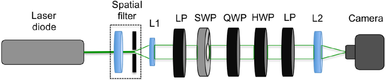
Figure 1. Schematic diagram employed for the experimental determination of the Spatial Average Symmetry associated to unconventional polarized beams of light. A light beam is spatially filtered and then collimated by lens L1; LP represents a linear polarizer; SWP represents the S-waveplate converter; QWP and HWP represent quarter- and half-waveplates, respectively; L2 is a lens employed to form an image on the plane of a CMOS camera.
A laser diode is employed as the source of monochromatic light (Thorlabs, laser diode model DPSS, @532 nm), which is spatially filtered to produce a uniform intensity, which is then collimated by a lens, L1. A linear polarizer with its transmission axis parallel to the optical table generates a conventional linear polarization incident at the S-waveplate (Altechna, model RCP-515-06), which generates the unconventional polarizations reported here, except along the optical axis, where there exists a singularity1. The Stokes parameters for both azimuthal and radial polarizations are obtained by applying Eq. (5) to the beam generated, and the spatial average symmetry, (Eq. 7), is calculated by using a Matlab code generated by authors.
Figure 2 shows the normalized experimental Stokes parameters for azimuthal polarized light.
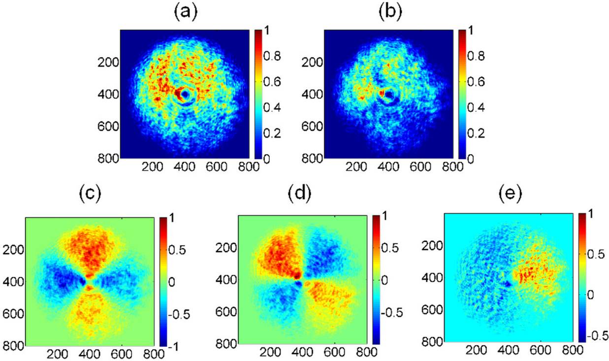
Figure 2. Stokes parameters associated to the experimental azimuthal polarization, (a) intensity spatial distribution as detected by the CMOS camera, (b) S0, (c) S1, (d) S2, (e) S3. Spatial average symmetry,
Figure 2(a) represents the total intensity measured directly by the CMOS camera (the intensity depends on the exposure time; it has been registered trying not to saturate the image). Similar images were taken several times, with different exposure times, exhibiting high reproducibility, where a small deviation from a perfect symmetry can be seen directly from Fig. 2(a). It is important to take into account that the intensity distribution generated is supposed to be associated only to to azimuthally distributed polarization; however, it must be tested by the user in order to check the quality of the unconventional polarization generated. Figure 2(b) is associated to the S
0 total intensity measured according to Eq. (5); note it is not axially symmetric, but shows only positive values, as expected for the total intensity distributed spatially. All the Stokes parameters reduce their intensities with respect to the original image, due to the attenuation present within the polarization state analyzer setup (Fig. 1). This intensity reduction is clearly noted in the S
0 element, Fig. 2(b). Figure 2(c) represents S1, with both positive and negative contributions to the intensity spatial distribution. Figure 2(d) shows the contribution to linear 45°, 135° polarizations. Finally, Fig. 2(e) shows the radial polarization contribution to circular polarization. Note that a visual appreciation does not allow determining if there exists any preferential or dominant polarization associated to Fig. 2; this is only qualitative information. This means that even when the experimental determination of the Stokes vector images provides more information, it is not conclusive, because it lacks numerical evaluation, which provides the average tendency followed by the polarization analyzed. On the other hand, the use of the Spatial Average Symmetry, SAS, defined by Eq. (7), plays a very important role, because it allows one to compute every Stokes image parameter in order to get the complete Stokes vector. The spatial average of the Stokes image parameters over the area of the image, Fig. 2, provides
The numerical simulations associated to the six polarization states are depicted in Fig. 3, where an azimuthal polarization mode (Eqs. 2, 3) is analyzed. Figure 3(a) corresponds to an azimuthal polarization analyzed with a linear horizontal polarizer (transmission axis set at 0°); the spatial intensity distribution is aligned along the vertical direction because the transmission axis is parallel to the electric field distributions associated to the analyzed beam. The remaining Figs. 3(b)-3(d), were obtained by rotating the linear polarizer at 90°, 45°, 135°, respectively. Figures 3(e) and 3(f) show the same contribution to circular right- and left-handed polarization contributions.
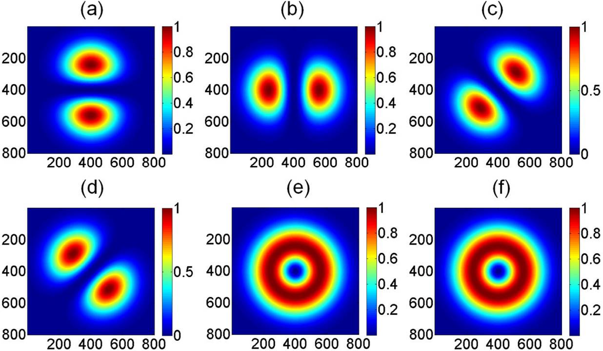
Figure 3. Analyzed polarization states associated to theoretical azimuthal polarization. Figs. (a), (b), (c), and (d) correspond to linear polarization states x, y, 45°, and 135°, respectively, while (e) and (f) correspond to circular right- and left-hand polarizations, respectively. Values are plotted in terms of pixels, and the intensity values have been normalized.
Applying Eq. (7) to the spatial intensity polarizations of Fig. 3, the theoretical Stokes parameters are obtained (Fig. 4).
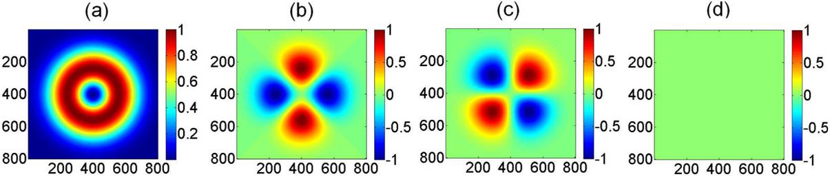
Figure 4. Stokes parameters associated to theoretical azimuthal polarizations, (a) S0, (b) S1, (c) S2, (d) S3. Spatial average symmetry,
From Fig. 4, the first element shows a perfect axial (in this case, circular) symmetry, while the second and the third elements apparently contribute with similar spatial average values to linear horizontal (x)/vertical (y), and 45°/135° polarization, respectively. Taking into account the polarization invariance associated to a perfectly circularly symmetric pattern, the same spatial polarization pattern for S1 and S2 should be expected, with the only difference that one is rotated 45° when compared to the other. This result is consistent with Figs. 4(b) and 4(c). The fourth element shows the same contribution to circular right- and left-hand polarizations, discarding any predominant contribution. The apparent conclusion, based only on the visual appreciation of the theoretical results, seems to show that there is no spatial average tendency to any polarization state. However, the quantitative information is provided by the Spatial Average Symmetry, Eq. (7), once it is applied to the Stokes parameters images depicted in Fig. 4, giving
Figures 5 and 6 show the experimental and the numerical simulated results, respectively, obtained for a radial polarization mode. From Fig. 5(a), note that the radial polarization generated is not perfectly symmetric, even when a linearly polarized collimated beam with uniform intensity was incident on the polarization converter. The Stokes parameter S0, Fig. 5(b), also exhibits the effect of the intensity diattenuation due to the linear analyzer. Figures 5(c) and 5(d) represent the second and third Stokes elements, respectively, and they are very similar, with the exception that one is rotated 45° with respect to the other. The Stokes element S3 shows spatial contributions to both, right- and left-hand polarizations.
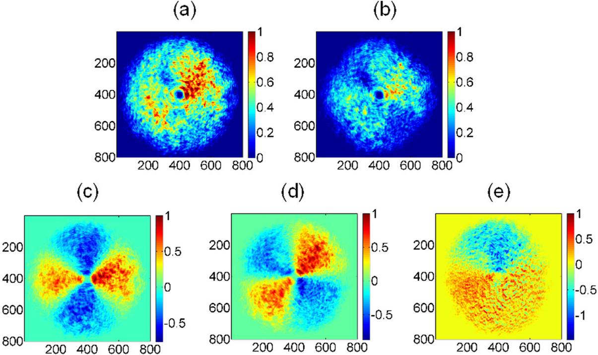
Figure 5. Stokes parameters associated to experimental radial polarization mode, (a) intensity spatial distribution as detected by the CMOS camera, (b) S0, (c) S1, (d) S2, (e) S3. Spatial average symmetry,
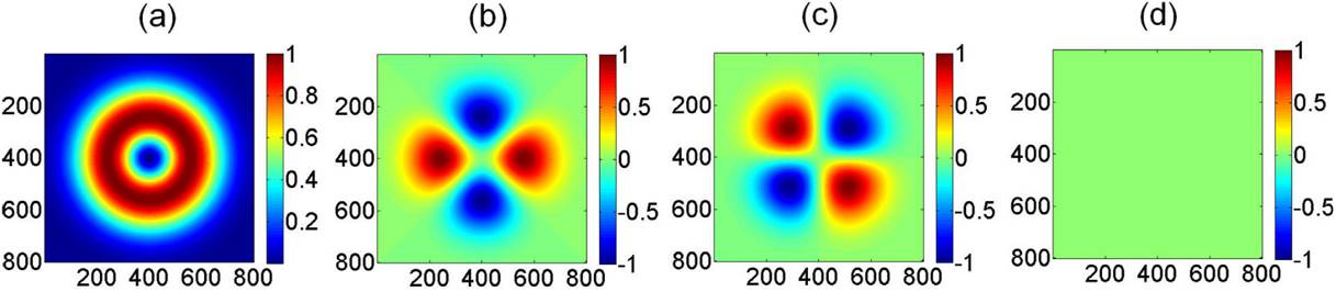
Figure 6. Stokes parameters associated to theoretical radial polarization, (a) S0, (b) S1, (c) S2, (d) S3. Spatial average symmetry,
Once again, Fig. 5 provides only qualitative information. The quantitative information is obtained by applying the Spatial Average Symmetry, Eq. (7), to the experimentally determined Stokes image parameters depicted in Fig. 5, where
The theoretical results obtained for the radial polarization mode (Fig. 6) can be easily understood considering that the intensity associated to the electric field components is transmitted along the transmission axis of the linear polarizer employed as analyzer (Figs. 6(a)-6(b)). On the other hand, the SAS calculated from the theoretical Stokes image parameters, Fig. 6, is provided to be
4. Conclusions
Stokes parameters have been determined, both experimentally and theoretically, for azimuthal and radial unconventional polarizations, using images and algebraic basic expressions. The spatial average Stokes was proposed as a way to quantify the spatial average symmetry associated to the beam’s cross-section when unconventional azimuthal and radial polarizations have been generated from conventional linear polarization states using a commercial passive converter. The results obtained are consistent with the theoretical considerations.
It is important to point out that the intention of this report is not to test the quality of the polarization modes generated by the commercial device employed here, because it depends on many factors related with the experimental conditions employed (centered incident beam, alignment of the mark with respect to the incident linear polarization, incidence direction perpendicular to the face of the S-waveplate, and diameter of the spatial filter employed, among other experimental factors). The objective of this report is just to show the importance of the spatial average Stokes vector, denoted here as the Spatial Average Symmetry, Eq. (7), because it provides quantitative information of the spatial average intensity associated to unconventional polarization states. The application of the proposed criterion to other arbitrary unconventional polarization modes could be a useful tool.

