


 text new page (beta)
 English (pdf)
 Article in xml format
 Article references
 Send this article by e-mail
 Cited by SciELO
  Similars in
SciELO
Similars in
SciELO 
 Permalink
PACS: 62.20.Dc; 62.20.Fe; 62.20.Mk
1. Introduction
At present, ASTM F-75 alloy (CoCrMo) is one of the most important alloys used for orthopedics applications. This alloy is characterized by a superior wear and corrosion resistance and a high level of hardness. Therefore, it is the metal of choice for articulating the surface of joint hip and knee replacements1. Despite numerous applications in orthopedics, which are partly based on its corrosion resistance, this alloy has a long history in aerospace and gas turbine industries which exploit its hardness as an important mechanical property2. The use of surface coatings offers a possibility to design materials having required properties for a special demand.
Several technologies are currently used in the industries for the surface hardening of steels, ferrous or non-ferrous alloys, and some super alloys3. In addition to the high level demand in the improvement of surface hardening, it is also extremely important to improve the industrial processes by increasing the resistance of materials against wear4. With the emergence of high-speed processing technology, this issue has become very relevant4,5. Therefore, the modern hardening techniques are expected to gratify these requirements. The improvement in hardness can be obtained via coating or diffusion penetration on the metal by a process such as nitriding, carburization, carbonitriding, physical vapour deposition (PVD) method, chemical vapour deposition (CVD) method etc.5,6,7,8,9. Although, these treatments improve wear performance, coating techniques have adhesion problems, while diffusion penetration as thermochemical treatments have excellent adhesion bonding between diffusion layer and substrate but they are expensive and require complex equipment. In recent years, the boronizing (also called boriding) process has emerged as an alternative4,10,11,12,13,14,15,16,17,18,19,20,21,22,23, and now accepted as an excellent choice for surface hardening. This process takes the advantage of the phenomenon of diffusion of boron into the metal surface to create the boride diffusion layer by heat treatment. The final boronized metal surface shows improvement in its mechanical properties such as greater hardness, better wear resistance, and greater resistance to corrosion and oxidation15,22. Although there are several boronizing methods16), (17), (18,19,20,21 and many formulations11,24,25,26,27,28,29,30 to produce the boride layer, this study considered boronizing process by employing a boron commercial paste.
Although, there are several studies investigating the boride hardness surface using different conditions11,12,13,14,15,16,17,18,19,20,21,22,23,24,25,26,27,28,29,30, none of them used RSM to investigate the optimal conditions in boride process18,31,32,33,34,35,36,37. RSM is an experimental methodology, which allows finding of the optimal conditions of a process in an experimental region that is delimited by the experimental range of each factor, for determining the optimal values for the factors and predict target response38. RSM reduces the number of experimental trials and helps in interpretation by making feasible the analysis of a large number of factors and delineating their possible mutual interactions39. Therefore, a systematic study of this process using RSM is very useful, and served the main objective of this research. This work was focused on the study of the surface hardening of ASTM F-75 alloy using the boronizing paste technique by RSM.
2. Experimental procedure
The boronizing process was carried out by employing the commercial Durborid® boron paste (typical it consists of 5 wt% B4C powder diluted with 90 wt% SiC of refractory material and 5 wt% KBF4 as a flux). For thermal treatments, an alumina crucible and a conventional Barnstead International muffle, model FB1415M, were used. The X-ray diffraction (XRD) measurements were performed with a Rigaku X’pert diffractometer using the CuKa line (
2.1. Preparation of the samples
ASTM F-75 alloy (CoCrMo alloy) was used as a substrate (25.4 mm diameter x 4 mm thickness). The chemical composition of CoCrMo alloy has a balanced weight percentage cobalt, 28-weight percentage chromium, and 6-weight percentage molybdenum. All samples were mechanically polished using SiC sandpaper from 240 to 1200 and then diamond paste with a mesh size of 3200 (7.9
2.2. The boronizing process by response surface methodology
RSM was applied for the boronizing process. This methodology was used to design and optimize the boronizing process by considering two factors: temperature and time, and constructing a prediction model for the Vickers hardness, HV (response variable). A factor is a variable that is investigated in an experiment to understand as it affects the response variable. The values assigned to each factor in the experimental design are called levels, these levels are codified (1.41, 1, 0, -1, -1.41) to facilitate the interpretations and calculations in experimental designs.
A central composite design (CCD) was used in the RSM to develop the experimental design. The coded levels and theirs values of the boronizing process are shown in Table I. The experimental data was evaluated by the analysis of variance (ANOVA), using STATGRAPHIC software. The design was based on a 22 factorial design completely randomized with three replicas. The CCD experiment was performed with 30 experiments: 4 factorial points (3 replicates), 2 central points and 4 axial points (3 replicates).

Each specimen was placed inside a dry pressing die of 50.8 mm diameter, and then 70 g of the boron paste was spread on the surface to deposit a layer having a thickness of about 3 cm. In order to enhance the contact, a load of 16 kN was applied over the pressing die for 10 min. Finally, the sample was placed on an alumina crucible and inserted inside the preheated muffle at the desired temperature and time as mentioned in Table I. The high temperature, shown in Table I, is not only acceptable for the lab, but also it is well applicable for industrial processing, while the low temperature is enough to activate the diffusion in the material.
After the boronizing process, the residual paste left on the surface was cleaned by washing the samples in boiling water and then were brushed using a toothbrush. Finally, the samples were washed consecutively in the ultrasonic bath as mentioned earlier.
2.3. Analysis of layer
The hardness test was performed before and after the boronizing process as per the ASTM E384 standard. The measurements were carried out by applying a load of 9.81 N for 15 s. The phase structure of the optimal boride diffusion layer was analyzed by X-ray diffraction method (XRD). The boride layer was evaluated on the cross sections by optical microscope (Olympus BX60), the sample was prepared by conventional metallographic and etching using a solution of 3 % HNO3, 1 % HCl and 94 % C2H6O.
3. Results and discussion
The hardness of the material ASTM F-75 before boronizing was 387
Table II. ANOVA for Hardness (HV).
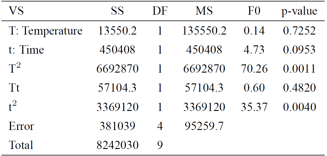
VS = variability source; SS = sum of squares; DF = degrees of freedom; MS = mean square; F0 = test statistic; p-value = observed significance
A regression model was applied to the experimental data to predict the value of hardness (HV) at the different values of the factors employed. Temperature (T) and time (t) were used as the parameters to model HV. Eq. (1) is the regression equation for HV. This expression is applicable only within the experimental region; the magnitudes of the variables are specified in their original units.
An analysis of the response surface and contour plots helped in optimizing the efficiency of HV. Fig. 1 shows the response surface for HV indicating the mean hardness value (HV) in the experimental region. The response surface of the HV increased with increasing the time from 6 h to 6.8 h however, when the time was increased from 6.8 h to 8 h, the HV decreased. Interestingly, a similar effect on the temperature was also observed; when the temperature was increased from 700°C to 780°C, the HV increased, but when the temperature was increased further from 780°C to 900°C, the HV decreased. The RSM enabled us to determine the optimal region and depict the optimal response; and it demonstrated the optimization of the boronizing process parameters for HV.
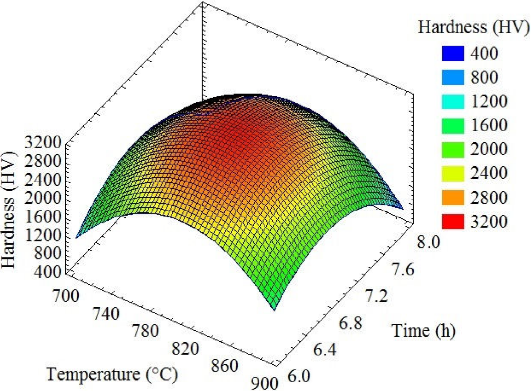
Figure 2 shows the contour of estimate response surface for hardness (HV). The optimal point for this model is shown in the figure. The levels that maximize 3139.7 HV (30.79 GPa) over the indicated region are a temperature of 802.4°C and duration of 6.86 h.

It is important to note that the optimal hardness estimated by RMS is higher than earlier published hardness results18,33,34,40,41,42,43. Although the data obtained by these authors did not use the same indentation conditions (indentation load and time), the hardness can be properly compared since these authors use the same standard.
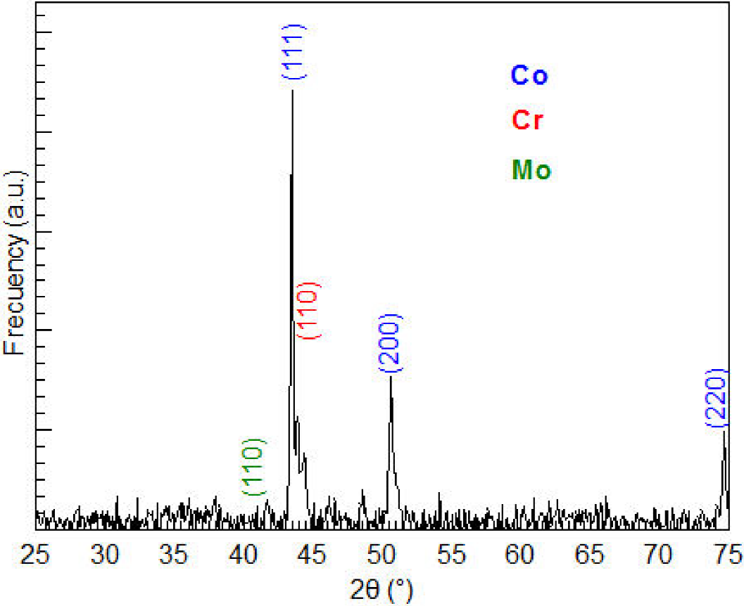
Figure 3 shows the X-ray diffractogram of the sample before boronizing. The positions of the diffraction peaks associated with the crystal structure of Co, Cr and Mo, obtained respectively from 150806, 60694 and 421120 card of the powder diffraction files (PDF) database, are also shown. The X-ray diffraction analysis confirms that the material is composed at least of Co and Cr because there is a complete correspondence between the diffraction peaks observed and those mentioned in database.
The samples prepared at 800°C and 7 h were in the best hardness conditions. In this sense, X-ray characterization of the samples prepared at this temperature and time was carried out. Figure 4 shows the X-ray diffractogram of the sample subjected to the optimum thermochemical hardening with boron. The positions of the diffraction peaks associated with the crystal structure of CoB, Co2B, CrB and Mo2B, obtained respectively from 30959, 250241, 320277 and 250561 card of the powder diffraction files (PDF) database, are also shown. The X-ray diffraction analysis confirms that the boride layer is composed of CoB, Co2B, CrB and Mo2B crystals, as there is a complete correspondence between the diffraction peaks observed and those mentioned in database. The strong and sharp diffraction peaks further affirm the crystalline nature of the layer.
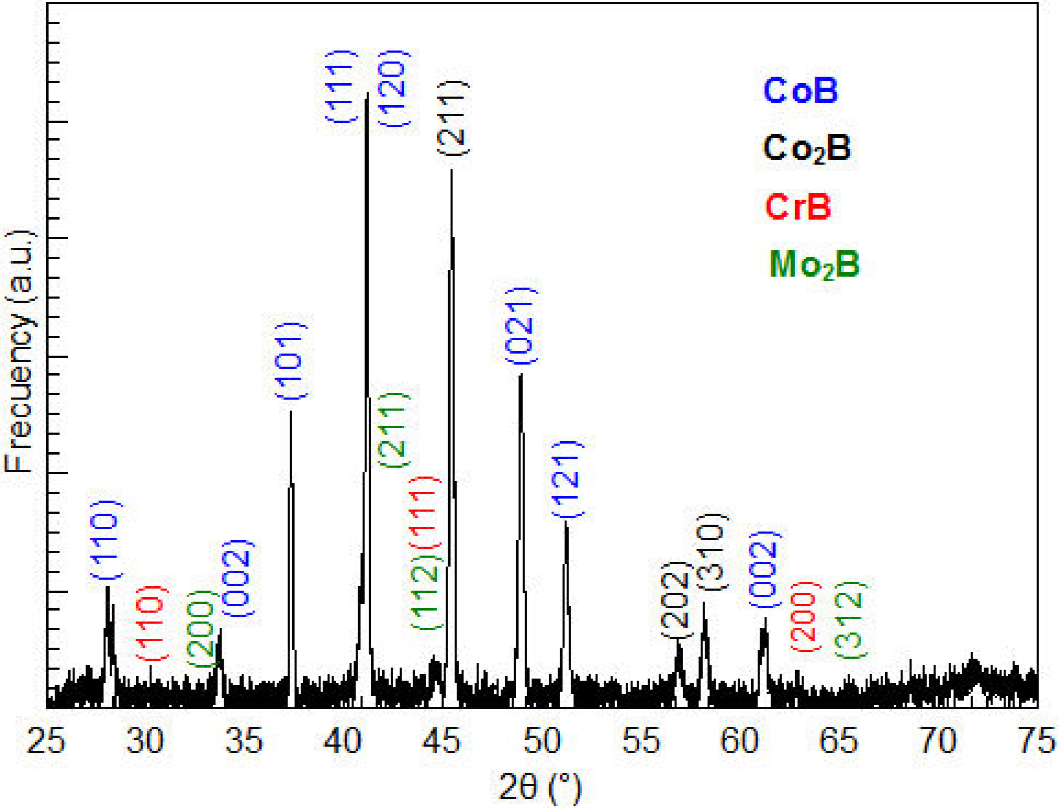
Figure 4. XRD pattern obtained at the surface of the boride ASTM F-75 cobalt alloy. The boronizing temperature was 800°C and the treatment duration was 7 h.
The X-ray results suggest that the boron atoms diffuse into the material surface reacting with Co, Cr and Mo. It is assumed that the following reactions would take place simultaneously on the sample increasing the hardness of the boronized material on the surface:
During the annealing process, B4C becomes unstable and boron is liberated, and then it diffuses to interact with Co, Cr and Mo forming a boride layer which consists of complex borides mixture, Eq. (1-4). Since the Vickers hardness of CoB, Co2B, CrB and Mo2B phases have been measured as 30 Gpa33, 17 GPa33, 17 GPa44 and 24.4 GPa45, respectively, these phases are responsible for the increased hardness, which is probably the closest to the phase hardness value of greater volume fraction in the boride layer.
Figure 5 shows an optical micrograph of the cross-sectional microstructure of the boronized sample prepared at 800°C and 7 h. The obtained thickness of the boride layer is
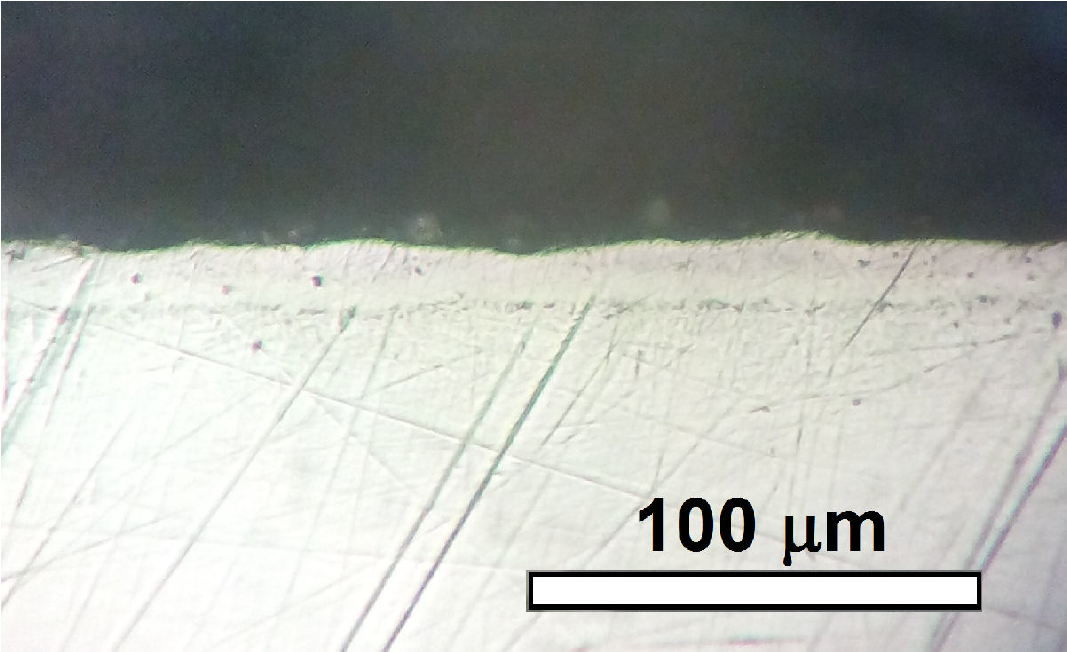
Figure 5. Optical micrograph of the cross-sectional microstructure of the boronized sample. The boronizing temperature was 800°C and the treatment duration was 7 h.
Even when the boronized layer is constituted by a mixture of phases as CoB, Co2B, CrB and Mo2B, at this resolution, the outer layer in Fig. 5 seems formed by one phase.
4. Conclusions
In this study, the statistical design of the experiments and the RSM were found to be powerful tools for the planning and analysis of the experiments determining the influence of temperature and time of the boronizing process on the hardness of boride ASTM F-75 layers. The calculated regression models were found to be statistically significant at the required range and all experimental data fitted well with an R2 value of 0.954.
A second-order polynomial response surface equation was developed in order to analyze the effect of variables on the layer hardness. The model shows that temperature has a significant effect, while time has no significant effect on the hardness. However, a proper combination of temperature and time of the boriding process can achieve a high level of hardness. The most optimal conditions, for the boriding process, were: temperature at 802.4°C and the duration of 6.86 h. Under this condition, the maximal hardness of 3129.7 HV was achieved.
Finally, the X-ray diffraction analysis confirmed that the boride layer of the best sample was composed of CoB, Co2B, CrB and Mo2B and the thickness of its boride layer is

