


 text new page (beta)
 English (pdf)
 Article in xml format
 Article references
 Send this article by e-mail
 Cited by SciELO
  Similars in
SciELO
Similars in
SciELO 
 Permalink
PACS: 47.10.ad; 02.60.Cb; 44.20.+b
1. Introduction
The study of fluid and heat transfer over stretching surfaces have gained considerable attention in last decade due to its applications in wide range of industrial mechanism like polymer extrusion, crystal growing, wire drawing, cable coating, spinning of filaments and many more. Further an important phenomenon of suction or injection in the fluid through the bounding surfaces can significantly change the flow field and, as a result affects the skin friction coefficient and the heat transfer rate at the surface. It is well known that, suction helps to slow down the fluid motion which results in increasing of skin friction and heat transfer rate, whereas injection has totally different behavior 1. In all these cases, controlling the rate of heat transfer on the stretching surface is responsible for the good quality of product. The study on this topic was first considered by Crane 2, who investigated the boundary layer flow initiated due to stretching sheet and found the solution analytically. After the pioneering work of Crane 2, investigators subsequently extended the work to Newtonian and non-Newtonian fluids under different physical conditions (see 3-9).
The aforementioned references are related to heat and fluid flow characteristics over a stretching sheet and very less attention is given for the stretching cylinder. The study of fluid flow over stretching cylinder was first initiated by Wang10. In his study he converted the Navier Stoke equation in polar form. Following the Wang 10 some researcher have extended his work by incorporating different physical phenomena. Uniform suction/blowing effect on flow and heat transfer due to stretching cylinder is discussed by Ishak et al. 11. Ishak and Nazar 12 have studied the flow around stretching cylinder. They assumed that cylinder is stretching linearly in axial direction and found similarity solution. This work was extension of Grubka and Bobba 13 and Ali14, from a stretching sheet to a stretching cylinder. Ishak et al.15, Ganesan and Loganathan 16 discussed boundary layer flow and heat transfer over an unsteady stretching vertical surface and the magnetic effects on horizontal and vertical stretching cylinder, respectively. Abbas et al. 17 have studied the combine effects of MHD and porous medium over stretching cylinder. The thermal radiation through a porous medium was also incorporated by considering the fluid as transparent. Recently, Mukhopadhyay 18-19 studied the effects of MHD and mixed convection boundary layer flow over a stretching cylinder.
In all aforementioned studies, the fluid physical properties were taken to be constant. The physical properties of the fluid may change with temperature variation. Heat generated in lubricants effect the physical properties, so that these properties can no longer be remained constant. The increase of temperature significantly increases the fluid carriage phenomena by the reduction of physical properties across the momentum boundary layer and the heat transfer rate is also effected near the wall. Therefore, to predict the flow behavior accurately it is essential to take physical properties as function of temperature. After examine the literature on variable fluid properties (see 20-23), it is disclosed that lot of work can be done for flow and heat analysis over stretching cylinder with variable fluid properties. In present study, we analyze the effects of magnetic field and variable Prandtl number on flow and heat transfer over stretching cylinder. The governing non-linear ordinary differential equations have been solved numerically using the Chebyshev Spectral Newton’s Iterative Scheme (CSNIS) 24. The accuracy of the results is verified with previous studies through tables. All the calculations are carried out with thermo-physical effects and variable Prandtl number.
2. Mathematical formulation
We considered the steady two dimensional flow over a hollow cylinder with radius a. The fluid is assume to be viscous, incompressible and electrically conducting. The axis of the cylinder is along x-axis and r-axis is measured along radial direction as shown in Fig. 1.
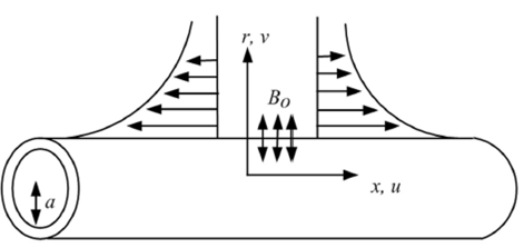
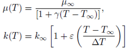
It is assumed that the cylinder is stretched along axial direction with Uw = b(x/L) and surface temperature of the cylinder is taken as Tw = c(x/L) where L and b represents the reference length and stretching rate of the cylinder respectively, c represents dimensionless constant. The phenomenon of suction/blowing prevails all over the surface of the cylinder with constant radial velocity vw . All the thermos-physical properties are considered as constant except that the fluid viscosity and thermal conductivity which are assumed as a function of temperature 26 in the following form.
 (1)
(1)
Where k ∞ and μ ∞ are thermal conductivity and viscosity of the fluid at the ambient temperature, ε = (k - k ∞)/ k ∞ is small parameter, γ is thermal property of the fluid, ΔT = Tw - T ∞ is the temperature difference, Tw and kw are temperature and thermal conductivity at the surface. The temperature dependent viscosity in Eq. (1) can be simplified as
Here A and Tr are constant dependent on physical situations. In general, A > 0 represents gases and A < 0 represents liquid. Typical values of γ and A for air are γ = 0.026240 and A = -123.2 (see Weast 29). Let fluid viscosity parameter θr is constant and defined by
which can be determined by the viscosity/temperature properties of the fluid under consideration. It is important to mention here that for γ → 0, i.e., μ(T) = μ ∞ (constant, from Eq. (3)), θr → ∞. As the viscosity is decreasing function of temperature for liquids and gases, it is increasing function of temperature. Therefore θr is positive for gases and negative for liquids. The boundary layer equations for continuity, momentum and energy with variable fluid properties under the above assumptions are
 (5)
(5)
 (6)
(6)
 (7)
(7)
where ρ ∞ be the density, Bo be magnetic field strength, T is the temperature of the fluid, cp is the specific heat, T ∞ is the ambient temperature and Q represents temperature dependent volumetric rate. Where Q > 0 refers to internal heat generation and Q < 0 represents internal heat absorption. The relevant boundary conditions are
Following Ishak and Nazar 12, we define the similarity transformations for Eqns. (6)-(8) as
Here η be the similarity variable, ƒ (η) and θ(η) are dimensionless quantities and v ∞ be the kinematic viscosity. ψ be the stream function for which we find the expressions of u = ∂ψ/r∂r and v = ∂ψ/r∂x. The expression of velocity takes the following forms
and Eqns. (6,7) becomes
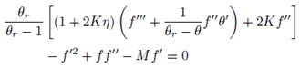 (11)
(11)
 (12)
(12)
With corresponding boundary conditions
Here
and prime denotes the differentiation with respect to η, K be the curvature parameter, M be the magnetic parameter, Pr ∞ be the ambient Prandtl number, β be the heat source sink and ƒw be suction/injection parameter, respectively. As by definition of Prandtl number, it is relation of viscosity, thermal conductivity and specific heat. It is well known that fluid viscosity and thermal conductivity varies across the boundary layer, therefore Prandtl number also varies. Moreover the assumption of constant Prandtl number inside the boundary layer with temperature dependent viscosity and variable thermal conductivity may leads to unrealistic results(see 25-28). Due to said reason, the variable Prandtl number is used here. The Prandtl number under the assumption of variable fluid properties is defined as
Upon using Eq. (15), the non-dimensional energy Eq. (12) can be expressed as
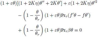 (16)
(16)
The quantities of interest for engineers and scientists are skin friction coefficient Cƒ and Nusselt number Nu respectively defined as
 (17)
(17)
 (18)
(18)
Utilizing the variables in (9), we get
Where Rex is Local Reynolds number.
3. Numerical method
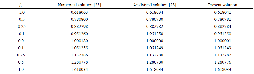
The solution of dimensionless boundary layer Eqs. (11,16) subject to the boundary conditions (13) is obtained by efficient numerical method named as Chebyshev Spectral Newton’s Iterative Scheme 24 (CSNIS). For the validity of numerical scheme the results are equated with already published studies as a limiting case and found excellent agreement (see Table I and II). The outline of the employed scheme is as follows:
Equations (11) and (16) with conditions (13) arelinearize by Newton’s linearization scheme.
The infinite domain is truncated to finite domain and then reduced to the interval [-1,1] by using transformation ξ = 2η/L - 1..
The grid point between -1 and 1 are defined by
The derivatives are replaced by a differential Matrix D, which is used to find the derivatives at collocation points.
Obtained matrix is solved by inverse method.

4. Results and discussion
The obtained boundary layer flow and energy equations are numerically solved by Chebyshev Spectral Newton’s Iterative Scheme. The numerical results are plotted graphically for different emerging parameters including curvature parameter K, magnetic parameter M, fluid viscosity parameter η, injection/suction parameter ƒw , variable thermal conductivity parameter, heat source/sink parameter β and the variable Prandtl number Pr v .
Figures 2(a), 2(b) and 2(c) demonstrate temperature profiles for different values of curvature and magnetic parameters by keeping ƒw = 0.0, -0.5, 0.5 respectively. The increasing values of curvature parameter leads to enhancement in thermal boundary layer thickness. This behavior is equally true for magnetic parameter, which in turn increases the temperature profile. It is noticed that in Figs. 2(b) and 2(c) thermal boundary layer thickness increases and decreases due to injection and suction respectively. Figures 3, 4 and 5 capture the effects of fluid viscosity parameter over a stretching cylinder for various curvature parameter K, keeping ƒw = 0.0, -0.5, 0.5 respectively. These lead to observation that with increasing values of θ r temperature decreases slightly for all values of ƒw . The decreasing trend of temperature profile and thermal boundary layer is observed with increasing values of injection parameter ƒw . The temperature distribution for different values of the curvature parameter K and the heat source/sink parameter β for both blowing and suction are presented in Figs. 6(a,b). From these graphs, we observe that the temperature distribution is lower within the boundary layer for negative value of β (heat sink) and higher for positive values of β(heat source). It is observed that temperature and thermal boundary layer thickness increase with the increasing value of the heat source/sink parameter β. Same behavior is observed for all values of the transverse curvature parameter K. Figures 7(a,b) is drawn to show the effects of curvature parameter K on temperature profile against η for different value of variable thermal conductivity parameter ε for both blowing and suction cases. These figures clearly indicate that temperature and thermal boundary layer thickness

FIGURE 2 The impact of K and M on temperature profile with Pr v = 0.71, ε = 0.2, θr = −3, β = −0.1 when (a) fw = 0.0 (b) fw = −0.5 (c) fw = 0.5.
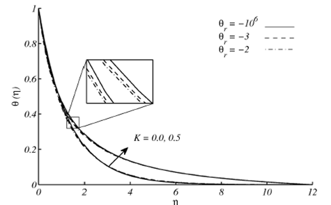
FIGURE 3 Temperature profile for different values of K and θr with Pr v = 0.71, ε = 0.2, M = 0.2, β = −0.1 when fw = 0.0.
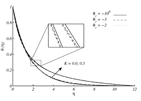
FIGURE 4 Temperature profile for different values of K and θr with Pr v = 0.71, ε = 0.2, M = 0.2, β = −0.1 when fw = −0.5.

FIGURE 5 Temperature profile for different values of K and θr with Pr v = 0.71, ε = 0.2, M = 0.2, β = −0.1 when fw = 0.5.

FIGURE 6 Temperature profile for different values of K and β with Pr v = 0.71, ε=0.2, M=0.2, θr =−5.0 when (a) fw = −0.5 and (b) fw = 0.5.
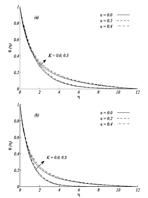
FIGURE 7 Temperature profile for different values of K and ε with Pr v = 0.71, β = −0.1, M = 0.2, θr = −5 when (a) fw = −0.5 and (b) fw = 0.5.
increases with increase of ε and K where as in case of injection, temperature and thermal boundary layer thickness is larger as compared to suction. Figure 8(a,b) show the temperature profile for different value of variable Prandtl number Pr v for both blowing and suction cases respectively. One can clearly see from these figures that an increase in variable Prandtl number leads to decrease in temperature profiles and hence thermal boundary layer thickness decreases.

FIGURE 8 Temperature profile for different values of K and Pr v with ε = 0.2, β = −0.1, M = 0.2, θr = −5 when (a) fw = −0.5 and (b) fw = 0.5.
Figures 9 and 10 exhibits the variations in variable Prandtl number in the domain of boundary layer for various values of the viscosity parameter θr with the fixed value of ambient Prandtl number Pr∞ = 0.71. Both figures show that the variable Prandtl Pr v asymptotically converges to the fix value of ambient Prandtl Pr∞ as η→∞. It is noticed that at the surface of cylinder Pr v approaches Pr∞ for large values of θr . It is also observed that Pr v decreases with increase in θr when it is positive while opposite behavior is observed for negative values of θr . Table III demonstrates the significance of variable viscosity parameter θr on the Nusselt number within the domain of boundary layer for both constant and variable Prandtl number.

FIGURE 9 Variation of variable Prandtl number Prv with ε = 0.2 for several values of θr (a) positive and (b) negative.

FIGURE 10 Variation of variable Prandtl number Pr v with ε = 0 for several values of θr (a) positive and (b) negative.
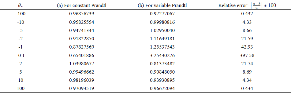
Numerical data shows that values of Nusselt number are smaller in a fluid of constant Prandtl number than a fluid of variable Prandtl number when θr . is negative and opposite behavior is seen for positive values of θr . The relative error is increasing when θr is decreasing and decreasing when θr is increasing. These variations in rate of heat transfer clearly support the argument that constant Prandtl number produce unrealistic results.
5. Conclusions
Hydromagnetic flow and heat transfer is examined in the present article. The fluid properties and Prandtl number are considered as a function of temperature. The solution of present problem is achieved by Chebyshev Spectral method having excellent agreement with published studies and fast convergent. The results of detailed information concerning the effects of emerging parameters is discussed. Important deductions of the present theoretical study are
Increase of curvature parameter results in enhancement of temperature in presence of variable fluid properties and Prandtl number
The increasing value of heat source/sink parameter boost up the temperature field.
Variable Prandtl Pr v asymptotically converges to the fix value of ambient Prandtl Pr∞ as η→∞.
At the surface of cylinder Pr v approaches Pr∞ for large values of θr
Pr v decreases with increase in θr when it is positive while opposite behavior is observed for negative values of θr .

