


 nueva página del texto (beta)
 Inglés (pdf)
 Artículo en XML
 Referencias del artículo
 Enviar artículo por email
 Citado por SciELO
  Similares en
SciELO
Similares en
SciELO 
 Permalink
Introduction
Solid waste is a non-liquid and non-gaseous product of human activities which could pose threat to both surface and groundwater systems. The environment of disposal is referred to as dumpsite and is defined as a place where refuse or other discarded materials are dumped (Ariyo and Enikanoselu, 2007). In Nigeria and other developing countries worldwide, wastes are mostly dumped on open grounds, landfills and in water bodies, constituting serious environmental and health problems and posing a major problem on groundwater. Contamination from solid wastes begins with the release of leachates into land surface and ends with the water reaching groundwater. Precipitation on the refuse dumpsite will either infiltrate the refuse or run off as over land flow (Ariyo and Enikanoselu, 2007). During the vertical percolation process (with rain water) the water leaches both organic and inorganic constituents from refuse and becomes part of the groundwater flow system when they reach the water table (Langer, 1998; Baba and Tokogoz, 1999; Christoph and Dermietzel, 2000; Rao et al., 2001; Baba, 2003). "The most common approach for investigating leachate plume migration from a dumpsite is to drill a network of monitoring wells around the site. However, these wells are expensive to construct and maintain" (Zume et al., 2006). "Additionally, limited information on subsurface hydrogeology and/ or budget limitations frequently compels the citing of monitoring wells at random. This approach is both technically and economically inefficient because monitoring wells give point measurements, whereas leachate plumes tend to migrate along preferential pathways, determined by subsurface heterogeneity" (Zume et al., 2006). Therefore, even with a network of closely spaced monitoring wells, the risk that some contaminants could go undetected remains high. For these reasons, there is widespread interest in applying noninvasive and relatively inexpensive geophysical techniques, such as electrical resistivity imaging (ERI), electromagnetic methods, electrical conductivity (EC) logging, and seismic surveys, as means for mapping the occurrence and movement of leachate and for facilitating decision making regarding the location of monitoring wells (Bernstone and Dahlin, 1997; Butler et al., 1999; Buselli and Lu, 2001). These geophysical methods have been used prior to waste disposal installations and for evaluation of possible leachate flow after dumping of waste because they generate nearly continuous image of the subsurface that can significantly reduce the risk of undetected contaminants (Zume et al., 2006; Olorunfemi and Mesida, 1987; Sharma, 1997; Schulmeister et al., 2003; Abu-Zeid et al., 2004; Naudet et al., 2004; Bayowa et al., 2012).
This article reports the application of the electrical geophysical method involving the vertical electrical sounding (VES) and 2D profiling (Dipole-Dipole) techniques to map possible leachate distribution and migration processes from the abandoned Ido Osun landfill site, Osun State, southwestern, Nigeria. The two techniques are based on the response of underground geologic features to a current flow field and are capable of detecting different subsurface units on the basis of the contrasts in electrical resistivity of earth materials (Telford et al., 1990). They are fast and cost effective. The former measures the vertical variations in resistivity of the subsurface earth while the latter involves the measurement of lateral and vertical variations of the apparent resistivity of the subsurface earth. The specific objectives of this study, therefore, were to delineate groundwater contamination, identify lithologic layers, locate possible leachate plumes, and assess the risk of groundwater pollution as a result of the dumpsite. This is with the view of assessing the risk associated with the groundwater abstraction in the area. The outcomes of this study will help appropriate decision-making on how and where to abstract underground water and remediation methods to adopt.
Study area
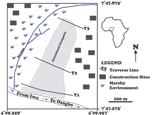
The study area, Onibuaje dumpsite, is located in Ido-Osun, Osun State, Southwestern Nigeria within Latitude 70 47.5751 and 70 47.8751 and Longitude 40 29.3591 and 40 29.9571 (Figure 1). The dumpsite used to be active and covered an area of (360 m by 220 m) with height that varied between 0.5 m to 3 m. It was abandoned in the year 2003 due to the government policy to salvage the area from further environmental pollution. A southward bound network of streams has given rise to marshy environment located west of the dumpsite. Several construction sites have begun to develop and other human activities have increased around the area since 2007. The only hand dug well in the vicinity of the area is seasonal in term of water content and it is only being used for construction purposes. Human activities will increase in this area and there will be need for potable groundwater for drinking, cooking and bathing in the future. The question is to what extent will the developing community be affected by the abandoned dumpsite since the safety and well-being of the people who will live in the area will depend on the abstraction of quality groundwater. Regionally, the area is underlain by quartzite which is a member of the Precambrian Basement Complex rocks of Southwestern Nigeria (Rahaman, 1988). The Basement Complex rocks have been classified into (1) Migmatite gneiss-quartzite complex, (2) slightly migmatized to non-migmatized metasedimentary and metaigneous rocks, and (3) members of the Older Granite Suite (Rahaman, 1988). These rocks constitute the prominent outcrops and inselbergs that define the topographic highlands in the area (Adediji and Ajibade, 2008). The area is characterized by tropical rain forest and has humid climate with an average temperature of between 21.1°C and 31.1°C and annual rainfall of about 1000 mm with the rainy season covering eight months; beginning in April and ending in November (OSSADEP, 1997).
Data collection and analysis
The survey which was carried out in 2012 involved the electrical resistivity techniques. Electrical resistivity surveys are usually designed to measure the electrical resistivity of subsurface materials by making measurements on or within the earth (Van Nostrand and Cook, 1966; Ebraheem et al., 1997; Zonge et al., 2005; Lowrie, 2007). An electrical current (I) is imposed on the ground by a pair of electrodes at varying spacing expanding symmetrically from a central point for VES while measuring the surface expression of the resulting electric potential (ΔV) with an additional pair of electrodes at appropriate spacing. The apparent resistivity (ρα) is given by:
Where ρα is the apparent resistivity and K is the geometric factor which takes into account the geometric spread of the electrode array. In this study, the vertical electrical sounding (VES) and 2-D imaging technique were adopted on three traverses established in NW-SE direction around the accessible parts of the dumpsite. The Schlumberger array was adopted for the VES while the dipole-dipole array was adopted for the 2-D imaging technique.
The Schlumberger Technique
The Schlumberger array is one of the most commonly used arrays and it is used mainly for resistivity sounding in a layered environment where it provides excellent vertical resolution. The depth of investigation of the electrode array is 0.125AB, where AB is the total current electrode separation (Roy and Apparao, 1971). It employs a four electrode system, two current electrodes C1 and C2 and two potential electrodes P1 and P2. The apparent resistivity (ρα) values were calculated from equation (1) and the results are presented as sounding curves and geoelectric sections. For Schlumberger array (1) take the form
Where ΔV/I is the ground resistance (measured in ohms), L (m) is half the currentcurrent electrode spacing (AB/2), l (m) is half the potential-potential electrode spacing and π is a constant (3.142 or 22/7).
Twenty-Six (26) VES data points were acquired on three traverses, namely, Traverse I, Traverse II and Traverse III (Figure 1) with ABEM Terrameter SAS 1000 using station interval of 20 m and half current electrode spacing varied from 1 to 65 m. The VES data were plotted on log-log graph while adopting partial curve matching technique to generate initial inputs for the 1-D forward modeling using InterpretVESTM software. The final VES layer parameters were used to produce 2-D geoelectric images along each traverse. The depth sounding curves obtained in the study area are grouped on the basis of layer resistivity combination into H, KH and A types (Table 1) and Figure 2.

Dipole-Dipole Technique
The Dipole-Dipole array is a 2-D imaging technique that involves the measurement of lateral and vertical variations in apparent resistivity of the subsurface earth (Roy and Apparao, 1971). The apparent resistivity is calculated from equation (3),
The ΔV/I = R (the ground resistance (ohms)) and spacing of the electrodes in each pair is a (m), while the distance between their mid-points is L (m), which is generally much larger than a. The measured resistivity values are plotted against the points of intersection of two 450 inclined lines from the mid - points of the current and potential dipoles. The interpretation usually involves the construction of geoelectric sections and inversion into 2D resistivity images.
Fifty-Two (52) dipole-dipole data points were acquired using 10 m station interval on the three traverses altogether. In the field, the expansion factor, n (distance between the leading potential and trailing current electrodes), was varied from 1 to 5 with a depth range of 2.9 - 6.8 m (Roy and Apparao, 1971). The data were processed using the DIPROfWinTM Version 4 software to generate 2-D resistivity images of the subsurface beneath the dumpsite below each of the three traverses after iterating 10 times. The inversion using the DIPROfWin software was based on FEM modelling. The absolute RMS Errors for the traverse 1, traverse 2 and traverse 3 are 0.311904, 0.385059 and 0.357008 respectively. The two survey techniques were carried out within three days with the same equipment. The combination of the geoelectric sections derived from the VES points on each traverse and the inverted 2D resistivity models were used to delineate possible subsurface resistivity layers, aquifer system and the quality of the aquifer fluid.
Results and discussion
Traverse I (T 1 )
Figure 3 shows the VES and 2D imaging results obtained on Traverse I. Table 1 reveals that H and KH curve types are predominant beneath this traverse. These curve types are usual pointers to the possibility of the occurrence of groundwater in the basement complex of Nigeria (Olorunfemi and Olorunniwo, 1985; Ako and Olorunfemi, 1989; Olayinka and Olorunfemi, 1992; Olorunfemi and Fasuyi, 1993). The VES geoelectric section (Figure 3A) is 220 m long and relates VES 1, 2, 3, 4,5,6,7,8,9,10,11 and 12 in the NW-SE direction. Three distinct geoelectric layers can be identified on the section. The first layer with resistivity values varying between 11 and 341 Ωm and the layer thickness values between 1.0 and 2.3 m was associated with the topsoil. The second layer with resistivity values ranging between 21 and 224 Ωm and depth to base of the layer ranges between 8.5 and 20.6 m was referred as the weathered zone. This is usually the groundwater interval. The third layer was taken as the fresh bedrock with layer resistivity values range between 113 and 3575 Ωm. Figures 3B and 3C represent the observed dipole-dipole pseudo-section, and 2-D Inversion Model respectively. The 2-D resistivity structure reveals relatively low resistivity values in the range of 5 and 14 Ωm typical of contamination zones (Adepelumi et al., 2005; Urish, 1983; Bayowa et al., 2012) between stations 2 and 8 at a depth range between 3 and 12 m; stations 10 and 12 at about 5 m depth and between stations 14 and 19.5 at depth range between 5 to 15 m. At the depth of detection of the plumes, it is apparent that the groundwater is contaminated.

Traverse II (T 2 )
H and KH type curves were obtained on this Traverse in most cases (Table 1). This is similar to traverse I and indicates groundwater potential below it. Figure 4 relates the VES and 2D-Imaging results of the Traverse. Figure 4A is a VES geoelectric section that relates VES 13, 14, 15, 16, 17, 18, 19, and 20. The total length of this traverse is about 180 m. The VES geoelectric section shows three major geoelectric subsurface layers as in traverse I. The first layer with layer resistivity varying between 19 and 262 Ωm and thickness range between 0.7 and 1.3 m was associated with the topsoil. The second layer was considered as the weathered zone with resistivity values ranging between 23 and 227 Ωm and depth range between 2.2(1.3?) and 19.1(15?) m while the third layer was taken as the fresh bedrock with resistivity values between 391 and 1991 Ωm. Figures 4B and 4C are the observed dipole-dipole pseudosection, and 2-D Inversion Model along the traverse respectively. The 2-D image indicates distinct low resistivity zones (Adepelumi et al., 2005; Urish, 1983; Bayowa et al., 2012) of possible contamination between stations 2 and 7 at about 10 m depth; stations 8 and 10 at a depth of 3 m and between stations 12 and 16 at a depth range between 0 and 8(11?) m.

Traverse III (T 3 )
Only H and KH type curves were obtained beneath this traverse as indicated in Table 1. Figure 5A is the VES geoelectric section that relates VES 21, 22, 23, 24, 25 and 26 along the traverse. The section spans a distance of about 120 m and shows four possible subsurface layers. The first layer with layer resistivity range between 83 and 658 Ωm and thickness range between 0.9 and 2.5 m was associated with the topsoil. The second layer with resistivity values that range between 541 and 566 Ωm and depth values between 2.6 and 3.2 m was taken as representing laterite. The third layer with resistivity values that range between 24 and 144 Ωm and depth values between 2 and 16.6 m was associated with the weathered zone while the fourth layer with resistivity values range between 723 and 4113 Ωm was depicted as the fresh bedrock. Figures 5B and 5C show a field dipole-dipole pseudo-section and 2-D resistivity structure of the subsurface beneath Traverse 3. Exceptionally low resistivity values suspected to be contaminant leachate plumes (Adepelumi et al., 2005; Urish, 1983; Bayowa et al., 2012) are observed between stations 2 and 4 at a depth range between 0 and 15 m; stations 5 and 6 at a depth of about 5 m and; stations 6 and 8 at a depth beyond 30 m.

Figure 5 Showing (A) VES geoelectric image, (B) field pseudosection, and (C) theoretical pseudosection (D) 2-D inversion model along traverse 3.
These results show that there is a high possibility that the underground water beneath the dumpsite is polluted. Moreover, the topsoil beneath the dumpsite is too thin to prevent percolation of leachates to underground water. Since the thickness of the weathered layer and the nature of the bedrock topography indicate that the study area is potentially a high groundwater accumulation and recharge zone, urgent steps must be taken to prevent probable water related diseases in the vicinity of the dumpsite.
Conclusions
This study has employed Schlumberger VES and Dipole-Dipole electrical profiling techniques to map the surface and delineate possible contamination of the groundwater in the vicinity of an abandoned dumpsite in IdoOsun, Southwestern Nigeria. The interpretation of the data has provided information as regards the subsurface geolectric layers, the bedrock topography, groundwater potential and possible groundwater contamination in the study area. Four geoelectric layers were identified and were depicted as the topsoil, the lateritic layer, the weathered layer, and the fresh bedrock. The geoelectric curve types indicate high groundwater potential in the area. The H-type is the most prevalent of all the multi-layer curves accounting for 48% of the total. The KH-type accounts for 45% and A-type curve accounts for about 7%. Distinct low resistivity zones corresponding to contamination plumes were delineated from the dipole sections. These low resistivity zones extend into the weathered bedrock and possibly suggest contamination of the groundwater in this layer. Groundwater abstraction should be done far away or subjected to adequate water treatment for the safety of the future residents in the vicinity of the abandoned dumpsite.

