


Serviços Personalizados
Journal

Artigo
 Inglês (pdf)
 Artigo em XML
 Referências do artigo
 Enviar este artigo por email
Indicadores
 Citado por SciELO
 Links relacionados
-
 Similares em
SciELO
Similares em
SciELO
Compartilhar

 Permalink
Geofísica internacional
versão On-line ISSN 2954-436Xversão impressa ISSN 0016-7169
Geofís. Intl vol.45 no.1 Ciudad de México Jan./Mar. 2006
A resistivity survey of phosphate deposits containing hardpan pockets in Oulad Abdoun, Morocco
Saad Bakkali
Earth Sciences Department, Faculty of Sciences and Techniques, Abdelmalek Essaadi University, Tangier, Morocco Email: saad.bakkali@menara.ma
Received: March 29, 2005
Accepted: August 11, 2005
Resumen
En la gran cuenca de Oulad Abdoun en Marruecos se inició la explotación de un nuevo depósito de fosfatos para reemplazar al de Grand Daoui que se encuentra agotado. Existen inclusiones estériles de caliche que dificultan la extracción de las rocas fosfatadas y que son difíciles de detectar. La resistividad de los caliches excede un valor de 200 Ω–m contra 80 a 150 Ω–m para la roca fosfatada. Se llevó a cabo un proyecto de prospección eléctrica con un equipo Schlumberger sobre una extensión de 50 hectáreas. Se obtuvieron modelos del perfil geológico mediante análisis de Fourier, y se logró localizar las inclusiones de caliche y cubicar las reservas de fosfatos de manera más confiable.
Palabras clave: Prospección geofísica, resistividad, fosfatos, análisis de Fourier, filtrado, Marruecos.
Abstract
In the great Oulad Abdoun Basin exploitation of a new phosphate deposit was begun after the Grand Daoui horizon was exhausted. Inclusions of sterile hardpan—so–called "disturbances" —are hard to detect and interfere with phosphate extraction. Their resistivity is above 200 Ω–m as against 80 to 150 Ω–m for the phosphate–rich mineral. A Schlumberger resistivity survey over an area of 50 hectares was carried out. Models of the geology were successfully obtained from Fourier analysis. A new field procedure was tested to deal with the presence of disturbances. Estimates of phosphate reserves were improved and better constrained.
Key words: Geophysical surveys, resistivity, phosphate, Fourier analysis, filtering, Morocco.
INTRODUCTION
Morocco is a major producer of phosphate, with an annual output of 19 million tons and reserves in excess of 35 billion cubic meters. This represents more than 75% of world reserves. Resistivity surveys have been successfully used in the Oulad Abdoun phosphate basin in Khouribga Province (Figure 1), which is about 120 km south of Casablanca. The present survey was carried out in the Sidi Chennane deposit which is a part of Oulad Abdoun basin, extending over some 800 000 hectares.
The Sidi Chennane deposit is sedimentary and contains several distinct phosphate bearing layers. These layers are found in contact with alternating layers of calcareous and argillaceous hardpan. In this field, extraction was begun after Grand Daoui deposit was exhausted. However, the new deposit contains many inclusions or lenses of extremely tough hardpan locally known as dérangements or disturbances, found throughout the phosphate bearing sequence. The hard–pan pockets are normally detected only at the time of drilling. They interfere with field operations and introduce a severe bias in the estimates of phosphate reserves.
Direct exploration methods such as well logging or surface geology are not particularly effective. However, the chemical changes which are detectable at the hardpan/phosphate rock interface produce an important resistivity contrast. Other factors such as changes in lithofacies and clay content and consistency appear to account for some additional resistivity difference. It was found that normal phosphate–bearing rock has a resistivity of 80 to 150 Ω–m while the hardpan typically features resistivity values of between 200 and 1000 Ω–m.
A pilot resistivity survey was performed over an area of 50 hectares. The purpose of this experiment was to try and map and constrain the anomalous regions corresponding to hardpan. A resistivity map was expected to allow the electrical resistivity signals to be imaged in 3D. We used a Schlumberger array with a span of 120 m designed to reach a depth of 40 m. The so–called disturbances appear at random so that the apparent resistivity map may be used by the operating personnel as a kind of radar to plan the sequence of field operations. We use traditional Fourier analysis to determine the amplitudes of the effects of the random disturbances, or any other resistivity anomalies that may be present.
OVERVIEW OF THE AREA OF STUDY
The Sidi Chennane phosphate deposit is within the Oulad Abdoun basin about 33 km south east of Khouribga and 24 km SSW of Oued Zem (Figure 2). Its boundaries are: West, meridian 372500 (Lambert), South, meridian 228000 (Lambert), East, highway RP22, and North, the outcrops of the basement of the phosphate–rock sequence. The climate of the phosphate plateau is essentially arid. Rainfall is from November to May and is usually below 400 mm. Vegetation is of sparse dwarf palm trees. Rural population subsists on cattle ranching and seasonal agriculture in small villages, or douars. Ground water is increasingly scarce. Scattered wells depend on an aquifer in the Turonian limestones at depths of 100 m or more, which is sealed by the Senonian marls. This aquifier is also the sole water supply for the various mining operations.
GEOLOGY
The phosphate mineral was deposited over a long time window from Maestrichtian (late Cretaceous, about 80 ma), to Lutetian (early Eocene, 40 ma). However, deposition was irregular. Some layers are missing. Oulad Abdoun Basin occupies most of the phosphate plateau which is bounded toward the north by red outcrops of pre–Cenomanian sediments forming anÃextension of the south edge of the Central Massif. The Western boundary is the Rhamna Range, the Beni Amir plain is to the South and the Upper Atlas of Beni Mellal extends to the East. The geology of the study area is well understood (see Figure 3 for stratigraphy).
The geologic section rests unconformably on Paleozoic schists and quartzites. The basement is well located and the sedimentary cover is fairly thick (Michard, 1975). The uppermost formations of the Maestrichtian and Eocene contain the phosphate–bearing strata which are 30 to 50 m thick. The earlier deposits, i.e. the lower 5 to 28 m, are clayey phosphates of Maestrichtian age. The upper 20 to 30 m are less homogeneous. They are layered phosphate marls and sandstones with some limestones of Eocene age.
Below the phosphate–bearing strata one finds up to 70 m of Senonian marls and limestone marls; 20 to 60 m of Turonian limestones; a Cenomanian formation of alternating gypsum marls and limestone marls; and finally 10 to 60 m of red marls and mudstones of pre–Cenomanian age.
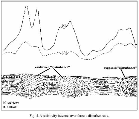
The disturbances may be differentiated by size of the pocket or inclusion, type of material, hardness, clay content, or type of contact with the phosphate rock. Two main types of disturbances are found. The first type is found throughout the mineral deposit: it appears to be a random mixture of limestones, marls, clays, cherts and low–grade phosphate with large amounts of cherty limestone. The second type is highly disturbed and lacks any dominant facies. It appears as an accumulation of low–grade phosphate limestone blocks with large nodules of chert, marl, some fragments of chert and phosphate rock. The latter type forms inclusions of 10 to more than 150 m and is the most abundant during mining operations (Figure 4). These pockets are found both in the underlying formation and in the upper members of the phosphate sequence, and as a result there are strong resistivity contrasts between the disturbances and the normal phosphate–bearing rock. These contrasts were confirmed in the test runs (Figure 5). Geophysical prospection could thus be based on prior evidence from field data.
FIELD PROCEDURES
Resistivity is an excellent parameter and marker for distinguishing between different types and degree of alteration of rocks. Resistivity surveys have long been successfully used by geophysicists and engineering geologists and the procedures are well established. The study area was selected for its representativity and the resistivity profiles were designed to contain both disturbed and enriched areas (Kchikach and Hiyane, 1991). The sections were also calibrated by using vertical electrical soundings.
High values of apparent resistivity were encountered due to the presence of near vertical faulting between areas of contrasting resistivity, and fault zones which may contain more or less highly conducting fault gouge. The gouge may contain gravel pockets or alluvial material in a clay matrix (Kchikach et al., 2002). Such anomalous sections are also classified as disturbances. Apparent resistivity values in these profiles locally exceeded 200 Ω–m.
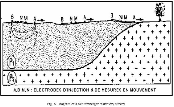
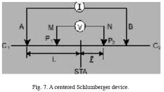
In order to locate and define the anomalous areas or disturbances, an electric current of intensity I was passed between electrodes A and B, and the voltage drop ΔV was measured between the potential electrodes M and N. The apparent resistivity is found from ρapp = K (ΔV/I), where K is the geometric constant of the instrument which depends only on the distance between electrodes (Gasmi et al., 2004). Thus the ratio between I and ΔV yields the resistivity of the terrain. Our Schlumberger set required the electrodes to be aligned and equidistant from the central point O so that MN<<AB (Figures 6 and 7). The longer the section, the deeper is the sensitivitÏ of the survey (Bakkali and Bouyalaoui, 2004).
The lateral inhomogeneities of the ground can be investigated by means of the apparent resistivity obtained from the survey. As the surface extension of the layers is displayed we may infer the presence or absence of any disturbances as well as any facies variations. Our resistivity measurements were performed by means of a Syscal2 resistivity meter by BRGM Instruments using a rectangular array of 20 m x 5 m. In order to reach a mean depth of exploration of 40 m we carried out 51 traverses at a spacing of 20 m. There were 101 stations at 5 m distance for every traverse, which makes 5151 stations all together in the survey (Bakkali and Bahi, 2005).
FOURIER ANALYSIS
Interpretation of resistivity anomalies is the process of extracting information on the position and composition of a target mineral body in the ground. In the present case the targets were essentially the inclusions called perturbations.
The amplitude of an anomaly may be assumed to be proportional to the volume of a target body and to the resistivity contrast with the mother lode. If the body has the same resistivity as the country rock no anomaly will be detected.
Apparent resistivity measurements are obtained from a harmonic potential V which fulfils Laplace's equation ΔV=0 in the surrounding space external to the body. The potential gradient falls off as 1/r2 (Blakely, 1995). As a first approximation, the scalar potential in the neighborhood of the perturbations and within the sources complies with the equation ΔV = –2ρl δ(r), where δ(.) is the Dirac delta, ρ is the resistivity in the anomalous region and I is the current at a point electrode in an elastic halfspace, i.e. the topographic surface of the study area (Telford et al., 1995). The apparent resistivity map which one obtains from such a survey is actually a map of discrete potentials on the free surface, and any major singularity in the apparent resistivities due to the presence of a perturbation will be due to the crossing from a "normal" into a "perturbed" area or vice versa. In other words, the apparent resistivity map may be considered a map of scalar potential differences assumed to be harmonic everywhere except over the perturbed areas. Thus one assumes that the potential difference data may be processed by Fourier analysis (Cooper, 2004).
Figure 8 shows the map of resistivity anomalies obtained by the EasyMapping3 routine from our apparent resistivity survey (Monnereau, 1997). This procedure enables us to define the sources, after a sequence of filtering operations by analytic prolongation and vertical second derivative projection. These standard procedures are basically Fourier filters which enhance some features of the anomaly map at the expense of other features, thus enabling us to connect the surface anomalies to the sources at depth.
Downward analytic prolongation will also amplify the effect of the deep structures, and enables us to separate the effect of adjacent sources (Rakotoniaina, 1999). To some extent it enables us to obtain an outline of the anomalous structures and, in any case, to find the depth to the roof of the body. Of course there is a possibility to confuse several structures with a single structure (Lutz, 1999).
The second–derivative operation is equivalent to high–pass filtering. It is useful for interpretation as it refines the response of the geophysical instrument, and it produces sharper contours. As derivation is sensitive to noise (Cooper and Cowan, 2003), this procedure enhances the expression of any structures and discontinuities.
EXPRESSION IN THE FREQUENCY DOMAIN
Let f,g,h be the data, the transformed data, and a filter; and let F, G, H be the respective spectral transforms. We process the data as follows.
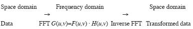
The data are imaged symmetrically in the space domain in order to minimize edge effects on the transformed map. Otherwise some spurious high frequency effects may appear around the edges.
The downward prolongation operator may be expressed in the frequency domain by a factor e2πvz, where z is the tageted depth. The frequency v may be defined as  , where u and v are the frequencies in the East and North directions (Gunn, 1975).
Once the resistivity map was filtered in the frequency domain the downward prolonged map at a depth of 50 m was restored back to the space domain by inverse Fourier transformation. Downward prolongation was carried out in steps of 10 meters which enabled us to sample the entire sequence of the phosphate formation. Numerical filtering was carried out with the SIGNAL2.1 software (Monnereau, 1997; see Figure 9). The vertical derivative operator in the frequency domain may be expressed as (2πv)2 (Gunn, 1975).
RESULTS
The resistivity map as obtained by the above procedure in the study area provided a direct image for an interpretation of the resistivity survey. We were able to identify the anomalies which turned out to be strongly correlated with the disturbances. We found that the disturbances as detected from surface measurements were distributed apparently at random with uniform density (Figure 8).
The map of resistivity anomalies was high–pass filtered with the second–derivative algorithm. The anomalous areas were neatly outlined. A possible area of coalescing resistivity anomalies was detected (Figure 9). As mentioned above, the disturbances were outlined in depth down to 50 m. Figures 10 and 11 show two anomalies which appear to coalesce at 50 m depth and practically grow together near the surface. The corresponding resistivity profile (Figure 12) fits the calibration tests (Figure 13). The high resistivities over anomalous areas are interpreted as reflecting the fact that the pockets of disturbed material tend to become more consolidated at depth. We find that the analytic prolongation procedure helps to better constrain the location of anomalous areas on the surface. When a second derivative procedure is also used, some additional improvement may be obtained and visualization of the anomalies in depth was found to be useful. The overall effect is that of scanning the anomalous bodies.
CONCLUSIONS
We have described a pilot study to test a geophysical application to a specific problem in the phosphate mining industry. The results proved satisfying. Resistivity surveys may be adapted to the specific field conditions in Western Morocco.
Values of resistivity in excess of 200 Ω–m correlated consistently with disturbances. Standard data processing procedures were found to be consistently useful and the filtered maps may be used as auxiliary tools for decision making under field conditions. It was found that the maps of vertical prolongation at different depths were particular useful to the surveyors for improving and constraining their estimates of phosphate reserves in the deposit. The set of resistivity maps may be used as a kind of radar image to plan the sequence of mining operations.
BIBLIOGRAPHY
BAKKALI, S. and J. BOUYALAOUI, 2004. Prospection géophysique appliquée à l'évaluation des eaux souterraines de Mediouna (Tanger, Maroc). Journal des Sciences Pour l'Ingénieur, J.S.P.I., 4, 13–22. [ Links ]
BAKKALI, S. and L. BAHI, 2006. Cartographie des <<dérangements>> de séries phosphatées par mesures de résistivités électriques. Journal des Sciences Pour l'Ingénieur, J.S.P.I., 6, (under press). [ Links ]
BLAKELY, R. J., 1995. Potential Theory in Gravity and Magnetic Applications, Cambridge University Press, 441. [ Links ]
COOPER, G., 2004. The stable downward continuation of potential field data. Expl. Geophys., 35, 260–265. [ Links ]
COOPER, G. and D. COWAN, 2003. The application of fractional calculus to potential field data. Expl. Geophys., 34, 51–56. [ Links ]
GASMI, M., H. BEN DHIA, P. ANDRIEUX and F. AMRI, 2004. Contribution de la prospection électrique à l'étude hydrogéologique des aquifères (Tunisie méridionale), Sécheresse, 15, 2, 201–8. [ Links ]
GUNN, P. J., 1975. linear transformation of gravity and magnetics fields. Geophysical Prospecting, 23, 300–312. [ Links ]
KCHIKACH, A. and M. HIYANE, 1991. Apport de la géophysique à la détermination des dérangements à Sidi Chennane Nord, Publications École Mohammadia d'Ingénieurs, Rabat, Maroc. [ Links ]
KCHIKACH, A., M. JAFFAL, T. AIFA and L. BAHI, 2002. Cartographie de corps stériles sous couverture quaternaire par méthode de résistivités électriques dans le gisement phosphaté de Sidi Chennane (Maroc). Comptes Rendus. Geosciences, 334, 379–386. [ Links ]
LUTZ, H., 1999. Cartographie, traitement et interprétation des données gravimétriques du fossé rhénan méridional (projet Geofrance 3D). Université Louis Pasteur Strasbourg I. Diplôme d'ingénieur de l'École de Physique du Globe, 83pp. [ Links ]
MICHARD, A., 1975. Les phosphates, Notes and Mémoires, N°276, Service Géologique, Maroc. [ Links ]
MONNEREAU, O., 2003. About EasyMapping software version 3.0, Manuel d'utilisation, Copyright 2001–2003 Olivier Monnereau. [ Links ]
MONNEREAU, O., 2003. About Signal software version 2.1, Manuel d'utilisation, Copyright 2001–2003 Olivier Monnereau. [ Links ]
RAKOTONIAINA, S., 1999. Traitement des anomalies en géophysique, Institut et Observatoire de Géophysique d'Antananarivo, Thèse de Doctorat, Institut & Observatoire d'Antananarivo (I.O.G.A), Université d'Antananarivo, Madagascar. [ Links ]
TELFORD, W. M. and R. E. SHERIFF, 1991. Applied Geophysics, Cambridge University Press, pp790. [ Links ]

