


 nueva página del texto (beta)
 Inglés (pdf)
 Artículo en XML
 Referencias del artículo
 Enviar artículo por email
 Citado por SciELO
  Similares en
SciELO
Similares en
SciELO 
 Permalink
1. Introduction
In the context of machining operations, the main problems affecting the quality of the machined workpiece are fundamentally (i) the static bending error of the workpiece, (ii) the machine-tool setup, and (iii) the dynamic problem known as “regenerative vibration” or “chatter”.
The first problem (i), namely the static bending error of the workpiece or cutting tool, results in undesirable final geometries; often, there is an excess of material. This problem can be solved by choosing optimized cutting strategies, by increasing the stiffness of the workpiece as much as possible, or, more analytically, by calculating the bending error to compensate the tool path.
Then, the error associated with the amplitude of the forced vibration (ii) appears in the same manner as the static error. If all rotating elements of the machine tool operate in dynamic balance, the only source of forced vibration is the tapping of the blades against the workpiece surface.
It can be noticed by observing the wear of the cutting edges or by the misalignment of the cutting tool (run-out).
Finally, the chatter phenomenon (iii) is a dynamic problem that results in the occurrence of undesirable vibrations. Such chatter tends to have very high amplitude, which can lead to either damage to the machine tool or to premature tool failure. It results in poor surface finishing in machining operations, tool breakage, and wear on the spindle components. Chatter directly affects the integrity of the machine performance and the workpiece quality.
Chatter theory was developed by Tobias and Fishwick (1958) in the late 1950s, followed by Tlusty and Polacek (1963), although Stone (2014) mentions the oldest reference about this topic is (Arnold, 1946). Tobias and Trusty explains the chatter phenomena as a regenerative phenomenon which is widely accepted because of self- excited vibrations in machine tools.
For half a century, many researchers have contributed to the theory of regenerative chatter development, including (Altintas & Budak, 1995; Defant & Albertelli, 2020; Guo et al., 2020; Merritt, 1965; Smith & Tlusty, 1990; Tlusty, 1985, 1986), among others (Azka et al., 2020a; Munoa et al., 2016; Paliwal & Babu, 2020; Urbikain et al., 2019).
Chatter research focuses on three areas, i.e. offline chatter prediction, online chatter detection and chatter suppression. Among them, chatter is avoided by offline chatter prediction and online chatter detection is the premise of chatter suppression. There are many literatures addressing the chatter issues during the machining process including the chatter mechanism (Altintas & Weck, 2004; Quintana & Ciurana; 2011; Wan et al., 2021) and mitigation strategies (Altintas et al. 2020). Studies discussed the machining stability influenced by the directional cutting force coefficients and directional stiffness of cutting systems in both serial machine tools (Azka et al., 2020a), and parallel kinematic machines (Azka et al., 2020b).
Zhu and Liu (2020) categorized different chatter mechanisms: regenerative chatter, mode coupling chatter, frictional chatter, and force-thermal chatter. Traditionally, the regenerative chatter is viewed as the main cause of the instability of the machine tool and CNC. Nevertheless, the mode coupling chatter frequently occurs in the robotic milling (Gienke et al., 2019; Yuan et al., 2018), such as serial robots or parallel kinematic machines (PKM). However, evidence shows robotic milling term refers to serial robots (Chen & Dong, 2013; Ji & Wang, 2019; Kim et al., 2019; Mejri et al., 2016; Mousavi et al., 2017; Nguyen et al., 2020; Pan et al., 2006; Zhu et al., 2021), rather than parallel configurations (Najafi et al. 2016; Pedrammehr et al., 2012; Shi et al., 2020; Tunc & Shaw, 2016). Serial robots are susceptible to mode coupling chatter due to the low structure stiffness of the robot. Thus, the entire robot structure can vibrate before regenerative chatter occurs.
Although the regenerative chatter and mode coupling chatter are co-existed, there are differences between them. The regenerative chatter happens locally at workpieces or cutting tools and it originates from the phase difference between the waves left on the upper and lower sides of the chip.
The mode coupling chatter happens globally, including the entire mechanical configuration and it occurs when the cutting plane vibrates in two directions. From the view of the frequency range, the frequency of the mode coupling chatter is lower (around 10 to 30 Hz, (Yuan et al., 2018). On the other hand, the frequency of the regenerative chatter is higher (from hundred to thousand Hz). Moreover, regenerative chatter occurs prior to mode coupling chatter.
Recently, regenerative chatter mechanism was shown to describe the stability of cutting tests much more effectively than mode coupling chatter in milling (Celikag et al., 2021). In addition, both chatters may occur depending on the distribution of the stiffness of an industrial configuration.
Stiffness is a very important factor in machine tool design (Dong et al., 2021; Zhang, 2009), as it affects the precision of machining. Induced vibration is explicitly linked to machine tool stiffness. For a metal-cutting machine tool, high stiffness allows higher machining speeds and feeds while providing the desired precision, thus reduces vibration, such as chatter. Therefore, to build and study a general stiffness model of parallel kinematic machines is very important for machine tool design. Moreover, a parallel kinematic machine promises to increase stiffness, higher speed, and acceleration due to reduced moving mass.
Where static stiffness is concerned, the aim is to remove mass maintaining a threshold value of stiffness, and for dynamic stiffness, the aim is to improve material removal rate and productivity. Moreover, it is the primary reason to define the dimensions and shapes of the machine tool structural components. For an accurate definition of the threshold values for dynamic stiffness, the best utility available is the stability lobes diagram (SLD) (Pan et al., 2006; Yue et al., 2019; Zhu & Liu, 2020). The SLD is a plot that separates stable and unstable machining operations for different spindle speeds. Stable cuts occur in the region below the stability boundary, while unstable cuts occur above the stability boundary. Also, to improve material removal rate and productivity, SLD is applied during the machining process to optimize the maximum depth of cut at the highest spindle speed.
This method can calculate analytically the approximate optimum depths of cut and determine the corresponding spindle speeds by obtaining four sets of input parameters, the cutting force coefficient, system dynamic behavior, process parameters, and tool geometry (Yue et al. 2019). Among them, cutting force coefficients and dynamic behaviour are two important inputs of SLD (Zhu & Liu, 2020).
In this paper, a method is presented to create the stability lobe diagram, based on (Yue, 2006), using common computational tools, applied to a 3 degree of freedom parallel kinematic machine. Therefore, the features that make the PKM ideal for machining tasks will be highlighted. Thus, the description on the progress of this work will be focused on three stages: (i) the resistance analysis of the structure withstanding static forces, (ii) the analysis of the natural frequencies and modes, and (iii) chatter prediction from the aspects of cutting force coefficient and the dynamic behaviour of the spindle/holder/tool system.
2. Theoretical development
2.1 Mobility
Fundamentally, material removal processes consist of three basic steps: i) positioning the placement head in the Cartesian x-y plane with sufficient precision, ii) translating/orientating about the z-axis, and iii) removing the chip using a wedge- shaped workpiece tool to obtain a finished product of the desired size, shape, and surface quality; meanwhile, the tool should be able to withstand the forces from the material- removal process. One of the main steps in the design and construction of a material-removal machine tool is the definition of its main motion. For a face-milling operation, mainly three-axis mechanisms are used. The three-axis movement is solved using a Cartesian configuration. In certain cases, all movements were assigned to the tool, whereas in other cases, movements were divided between the tool and the workpiece; less frequently, all movements are assigned to the workpiece.
2.2 Kinematic decoupling
A coupled mechanical configuration exhibits dependence on the mobility (i.e., most of parallel mechanisms (PMs)), this implies movement in two directions when only one actuator is activated. This type of motion requires advanced control techniques to be transformed into linear movements. Strong coupling refers to strong dependence of most operating parameters on the position and orientation. In a machining process, relative motion is required between the tool and the workpiece to perform a machining operation. In a basic metal cutting process, either the motion of the tool or the motion of the workpiece should follow a uniform path to guarantee a good surface finish, as well as to facilitate the analysis, the design, and the motion control. This uniform path depends on the ability of the configuration to perform a decoupled motion. Axis decoupling itself does not ensure a better surface finishing because the final surface finishing relies on several factors, including backlash and axis vibration; however, axis decoupling contributes to achieving it (Hong et al., 2003).
2.3 Isotropy
While in manipulation and assembly systems applications the domain over surface forces is more relevant, in machining applications the attention is focused on the direction of the cutting force. The machining processes require the same machining parameters along the entire tool path, and, simultaneously, the use of the entire available workspace. The force and the velocity direction of the tool, as well as the cutting conditions along the entire tool path, must be constant (Rehsteiner, 1999). This means that PMs must provide an isotropic force within a usable Cartesian workspace.
Using the concept of manipulability, it can be interpreted as the capability of a mechanism to move and apply forces in arbitrary directions (Staffetti, 2002). Manipulability can be represented geometrically as an ellipsoid for each position of the mechanism. The Jacobian matrix is assumed to map a unit sphere in the joint space onto the corresponding ellipsoid in the task space. When the ellipsoid becomes a sphere, the end- effector can move uniformly in all directions; such configuration is known as the isotropic configuration.
Zanganeh and Angeles (1997) defined the manipulability measures via the reciprocal of the condition number of the Jacobian matrix, J, which relates the gripper velocity, ẇ, to that of actuators, q̇, as well as the actuators forces or torques, Fq, to forces and torques, Fw, applied to the end-effector, which is given by
Geometrically, manipulability is the ratio of the length of the minor axis to the length of the major axis of the manipulability ellipsoid. In terms of achievable force, the isotropy properties of a parallel mechanism can be studied using the Jacobian matrix, J. The definition of the force ellipsoid is
whereJ=Jp-1Js, with
as the serial Jacobian matrix, and
as the parallel Jacobian matrix.
2.4. Introducing the 3 DoF PKM
The. three-prismatic-revolute-revolute-revolute (3-PRRR) configuration is a parallel mechanism with three legs, each being a 4 DoF serial mechanism (Gosselin et al., 2004) (Figure 1).
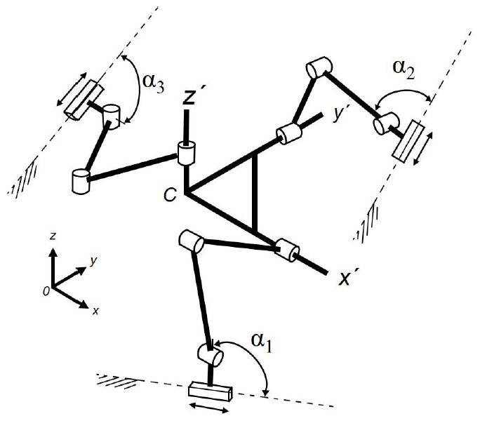
Each leg constrains two rotations. Therefore, the 3-PRRR configuration is an over-constrained mechanism. The terminal revolute joints of the three legs are connected to the mobile platform. The most influential design parameters of the 3-PRRR are angles α1, α2, and α3 (Gosselin & Kong, 2004). These angles determine the output resolution as well as the overall shape of the mechanism. The three resolutions are equal when α1 = α2 = α3 as well as the elements of the diagonal Jacobian matrix; the resulting mechanism is assumed to be isotropic (Zanganeh & Angeles, 1997). Moreover, the mechanism behaves exactly as a serial Cartesian mechanism when α1 = α2 = α3 = 0 (X-Y-Z stage) (Gosselin et al., 2004).
2.5. Assembly modes
The forward kinematic of the 3-PRRR PM yields an eight-degree polynomial in Px (Kim & Tsai, 2003). Therefore, it is possible to build eight different assembly modes from the same mechanism.
The Z actuator can be located anywhere perpendicular to the X-Y plane. The limbs that joint the moving platform and the XYZ actuators could have the “elbow” facing either up or down.
The 3-PRRR PM has a complete decoupling architecture, and it provides linear motion for each axis. Figure 2 shows a sketch of the machine.
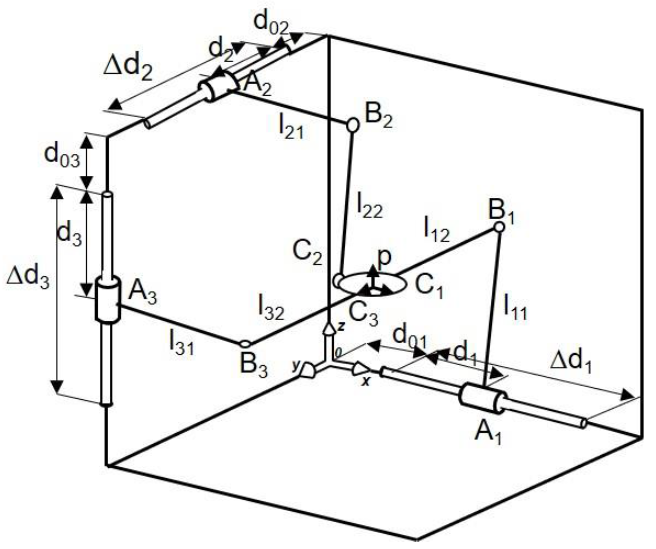
Regarding the kinematic analysis, a simple kinematic relation can be written as
where Px, Py and Pz define the position of the coordinate frame, XYZ. The starting point of a prismatic joint is defined by d0i and the sliding distance is defined by Δdi. The motion in each axis follows a linear trajectory, which implies that there is movement in one direction only when one actuator is activated.
Because the concept of the 3-PRRR PM is thoroughly symmetric, the length of all limbs is the same. The 3-PRRR PM presents an uncoupled kinematics and orthogonal configuration. Equation (5) shows that the Jacobian matrix of the 3-PRRR parallel configuration is the identity matrix.
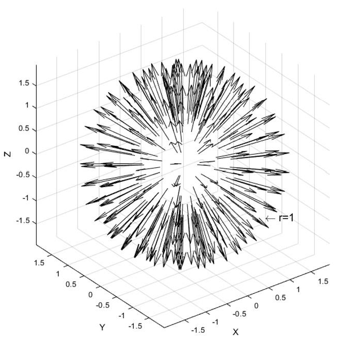
By substituting the identity matrix into Equation (2), we get
Equation (6) represents the equation of a sphere, as shown in Figure 3. Because the 3PRRR parallel architecture presents an uncoupled kinematics and orthogonal configuration, each of the linear actuators controls one of the translations. According to the isotropic index, the ratio of the length of the major semi axis and that of the minor semi axis is the same, i.e., wI(J) = 1.
2.6. Transmission factor
Because the Jacobian matrix is configuration-dependent, the force manipulability ellipsoid is configuration dependent as well. It may be observed from Equation (4) that the Jacobian matrix of the PKM is the identity matrix. Therefore, the mechanism is entirely decoupled. In addition, it can be guaranteed that there will never be any singularity inside the workspace. The force manipulability ellipsoid is equal to a sphere within the entire workspace and the transmission factor is equal to one in each assembly mode (Figure 4).
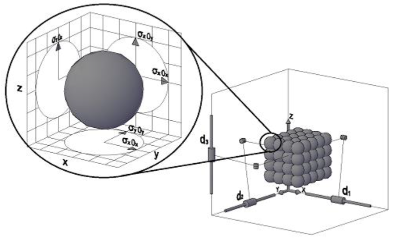
All the aforementioned features are suitable in a machine structure to develop cutting operations.
3. Stability model
For the evaluation of stability in working conditions it is necessary to have a model of the process where the cutting parameters, the workpiece material properties and the tool geometry are involved. The model follows the following steps: a) relation between the chip thickness and the vibration of the system is formulated, b) cutting forces model is proposed, c) the system dynamics is introduced, and finally d) the eigenvalue problem that defines the stability of the process is solved.
3.1 Equation of motion
For this stability model, the equations of motion will have the following form (Hong et al., 2003)
where Δ before the displacement and force vectors (namely, x(t) and F(t)) denotes small derivations from the equilibrium state, where the cutting force is balanced with the external driving force. Matrices M, C, and K represent the inertia, the damping, and the stiffness, respectively. The link mass is small compared with to the platform mass. The moving platform is assumed to be a rigid body and both mass and inertia are included in formulating the equation of motion. The links of the mechanism are modeled with springs and dampers of 1-DOF. This simplified model is reasonable, as is explained in (Hong et al., 2003), because only the axial force is exerted on the links of the PM.
Moreover, regarding chatter analysis, the overall analysis of the PM is not important because the mechanism moves with relatively slow speed within a workspace. Additionally, the first modal frequencies of the machine tool structure, workspace, and cutter are typically dominant in terms of causing chatter vibration. The modeling is limited to the end-milling and face-milling operation, where x and y with respect to the tool frame are the most decisive directions because they determine the machining accuracy and are based on regenerative chatter theory.
The model for the cutting force assumes the force, Fc, is proportional to the undeformed chip cross-sectional area (Lai, 2000; Stone, 2014), which in turn corresponds to the products between the depth of cut, p, and the chip thickness, d,
where ks is conventionally called the cutting force coefficient. It is assumed that this force does not depend on the cutting speed and so only vibration in the chip thickness direction is important. For constant amplitude sinusoidal motion and because of the regenerative effect of cutting, ΔF(t) depends on the difference of the present and the delayed tool position.
Here, τ denotes the time taken for one revolution of the work. Depending on the rotational speed and the frequency of vibration there will be a phase angle between the tool vibration x(t) and the surface wave x(t-τ). By substituting Eq. (9) in the general Eq. (7), we obtain the equation for the depth of cut (Stone, 2014; Tlusty, 1985).
where GR is the real part of the frequency response function (FRF), G, as the standard solution of Eq. (11) (Yue, 2006), which is
where k is the stiffness (k = F/x), r is the ratio of the chatter frequency to the natural frequency (r = f/fn), and ζ is the ratio of the damping coefficient, ζ = c/cc with cc = 2(km)1/2. By solving Eq. (5) and (7), the depth of cut, p, depends on the frequency of the regenerative vibration, f, or the natural frequency, fn, through ratio r. Thus, there is a critical depth of cut for each regenerative frequency in a machining process. Then, the metal-cutting process is assumed to be stable when its depth of cut is less than the critical value, and unstable when its depth of cut is greater than the critical value.
3.2. Cutting force
The engagement of the cutting edge with the rotating tool at a given depth of cut and feed rate generates a cutting force. This force undercuts a layer of material and separates it from a workspace in the form of chips. Such cutting force combines tangential (Ft), feed (Ff), and radial (Fr) forces in an orthogonal manner.
The specifications and the cutting forces that are present in a machining milling process are listed in Table 1. They were generated based on the mechanical properties of the work materials, the cutting condition, and the variables of the metal-cutting process state. All cutting conditions are proposed on the basis of practical knowledge and mathematic formulas taken from (Isakov, 2004), in which a method based on the definition of power, the cutting force and the cutting speed has been developed to increase accuracy when calculating machining power.
Table 1 Specifications and cutting forces of machining milling process.
| Specification | Cutting forces | |||||||
|---|---|---|---|---|---|---|---|---|
| Material | Ultimate tensile strength [MPa] | Tool diameter [mm] | Spindle speed [r.p.m .] | Linear feed [mm/ min] | Depth of cut[mm] | Tangenti al force [N] | Feed force [N] | Radial force [N] |
| Aluminum (6061-T6) | 200 | 0,2-6,35 | 36 000-3 600 | 20-300 | 0,02-2,00 | 0,77-367,6 | 0,33-157,7 | 0,16-77,56 |
| Brass (272) | 300 | 20-250 | 0,02-2,00 | 1,31-516,9 | 0,56-221,76 | 0,27-109,0 | ||
| Stainless steel (AIS 304) | 480 | 20-50 | 0,02-1,00 | 4,20-65,4 | 1,80-70,96 | 0,88-34,9 | ||
| Titanium (Ti6Al4V) | 900 | 20-30 | 0,02-1,00 | 6,56-155,0 | 2,81-66,5 | 1,38-32,72 | ||
3.3. Stability
A limit in the machining process is the minimum depth of cut, p min . It is independent of the frequency of regenerative vibration; therefore, the materials and geometries of the cutter and the workpiece determine a fixed value determined for the minimum depth of cut. A metal cutting process is stable when the depth of cut is below the critical value. A dimensionless depth of cut may be represented by the ratio of depth of cut to the minimum depth of cut.
From eq. (10) and (11) the minimum depth of cut occurs at the maximum negative value of G R when r = (1+2 ζ)1/2 (Yue, 2006). This is
thus,
The regenerative vibration equation is calculated assuming that there is always roughness or waviness on the machined surface of the workpieces owing to vibrations. The equation of the regenerative chatter is (Yue, 2006).
Equation (14) represents the relationship between the regenerative frequency, f, the cutoff frequency, f t and the lobe number, n. For each frequency generated, there is a corresponding critical depth of cut. Thus, the metal cutting process is unconditionally stable when the value of the depth of cut is below this critical value; otherwise, it is conditionally unstable. It may be graphically represented as the relationship between the depth of cut and the spindle speed by means of scallop-shaped chatter lines; the graph is referred to as a stability lobe diagram. The step-by-step procedure, based on (Yue, 2006), for generating the lobes is summarized in Table 2.
Table 2 Procedure to create SLD of N~p.
| a | Obtain parameters k, ks, r, an d γ and specify the number of teeth on the cutter, nt. |
| b | For each increment of j (1, 2, 3, 4, …) of the chatter frequency fj, calculate rj and p from Eq. (10). |
| c | For each lobe number, n, ca lculate its corresponding rtjn from Eq. (14). |
| d | For each rtjn, calculate the spindle speed using N = 60rtfn/nt. |
| e | The points for each n value are plotted to form a single lobe, and a series of lobes (n = 0,1, 2, …) are plotted to form the stability lobe diagram, N~p. |
Finally, Table 3 sums up a schematic description of the model for directly obtaining the SLD.
Table 3 Schematic method for directly obtaining the SLD.
| Approach | |
| Resolution of the periodic delay-differential equation | |
| Method | |
| Semi discretization | |
| a) Chip thickness model | |
| ℎj (𝜙, ) = 𝑓 t 𝑖𝑛 𝜙 (z) | |
| b) Cutting force model | |
|
| |
| c) System dynamics | |
| Modal parameters at the tool tip [𝐌(Ω)]{ẍ} + [𝐂(Ω)] {ẋ} + [𝐊(Ω)] {x} = {𝐅 (t)} | |
| d) Stability analysis procedure | |
| Analyze machining parameters and construct SLD | For a grid of cutting conditions, test if the eigenvalues of the matrix that defines the stability of the process have a modulus lower than 1. |
| Nomenclature | |
| a: Axial depth of cut. | |
| hj : Dynamic chip thickness of the j th cutting edge. | |
| ft: Feed per tooth. | |
| Fij : Total cutting forces over the axial depth of cut. | |
| Kt : Cutting force coefficients in the tangential direction. | |
| Kr : Cutting force coefficients in the radial directions. | |
| dz: Infinitesimal axial depth of cut. | |
| T: Tooth period. | |
| ωc: Frequency of chatter in rad/s. | |
| Λ: Reciprocal of the eigenvalues of the FRF G. | |
| Ω: Spindle speed in rad/s. | |
4. Case study
In the previous sections, we described the procedures to derive the frequency response function and the minimum depth of cut as stability limit for a PKM, with respect to the axial depth of cut and the spindle speed, utilizing the regenerative relations between the dynamic chip thickness and the cutting forces. In this section, the developed theories are applied to the case of a decoupled PKM.
4.1. The prototype description
For this prototype, the leg configurations were chosen in a manner that they would not interfere with the space that is around the end-effector. In turn, the mobile platform was designed to avoid leg interference and minimize the necessary lengths of the links. Regarding the links, they were chosen to be as long as necessary to allow the machine to have its maximum cube workspace of 250 × 250 × 250 mm. Furthermore, the 3-DOF PKM was designed in such a manner as to avoid any link interference.
This structure has advantages on linear motions along the coordinate axes. In addition, the decoupled design of the machine is proposed to eliminate any occurrence of mode coupling chatter, not only because of its decoupled design (kinematic decoupling), also because the spindle-toolholder-tool subsystem is independent to the structure of the machine.
A prototype of the 3-DOF PKM is shown in Figure 5. Standard thin-wall aluminum extrusion rectangular tubes were selected to be used as the proximal and distal links. The lengths of each link are listed in Table 4.
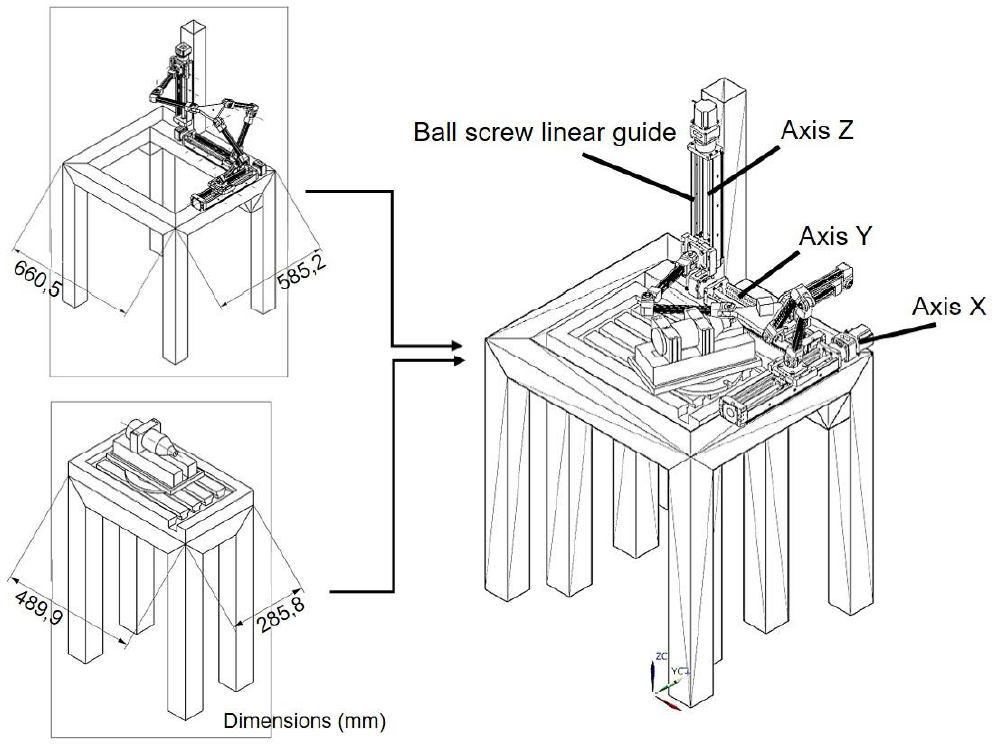
Table 4 Link lengths.
| Axis direction | Proximal link [mm] | Distal link [mm] | End- effector [mm] |
| X, Y, Z | 220 | 230 | 95 |
The critical-stiffness element of the machine is the spindle/holder/tool system. For chatter stability analysis only the frequency response function at the tool tip is required. Therefore, to obtain a reference measure of the required stiffness, the stiffness values of various modes of end mills clamped onto low-speed spindles were reviewed. The spindle inevitably has a limited stiffness because of the diameter of the bearing, the spindle shaft, and the thin tool. Typically, a low-speed spindle ranges within 5 000 to 35 000 rpm; produces a maximum power of 215 W. The toolholder consists of a single piece of material and is adjusted to an aluminum base that elevates the workpiece. End mills range between 3 and 13 mm in diameter and 30 and 50 mm in length. Three different brands of spindles with several different end mills were tested and measured.
The natural frequencies of the most dominant modes ranged within 1 300 and 2 800 Hz and the values of modal stiffness ranged within k = 1,5 N/μm and 6,9 N/μm with rather small damping ratios of ζ = 0,01-0,05, Figure 6. Therefore, it is possible to use these as references values and require that none of the structural modes of a well-designed PKM should have the kζ values of less than the kζ = 6,9 × 0,05 = 0,345 N/μm of the spindle modes, when reflected onto the tool end. Table 5 lists the geometric parameters and the mechanical properties of the PKM system that are required for the calculation of the stability lobe.
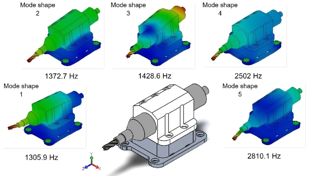
Table 5 Mechanical properties of the PKM.
| Components | Mechanical properties |
|---|---|
| End-effector | m = 0.020 kg, lx = 7.0x10⁻⁴ kg m2, ly = 3.4x10⁻⁴ kg m2 |
| Spindle/holder | fn = 1305.9 Hz, k = 1.9 N/μm, ζ = 0.05 |
| Cutter (end mill) | ks = 0.19 N/μm, nt = 4 |
It is convenient to write a code to calculate the approximate optimum depth of cut at the highest available spindle speed. Following the procedure described in Table 2, the results are summarized in Table 6.
Table 6 Calculating the stability lobes of N~p.
| j | fj | rj | pj | rtjn | ||||
|---|---|---|---|---|---|---|---|---|
| n = 0 | n =1 | n = 2 | n = 3 | ... | ||||
| 1 | 1306 | 1 | 6.33 | 9.967x10³ | 6.616x10³ | 4.951x10³ | 3.956x10³ | … |
| 2 | 1307 | 1.01 | 3.24 | 1.014x10⁴ | 6.704x10³ | 5.006x10³ | 3.995x10³ | … |
| 3 | 1308 | 1.01 | 2.24 | 1.031x10⁴ | 6.791x10³ | 5.061x10³ | 4.034x10³ | … |
| 4 | 1309 | 1.02 | 1.76 | 1.049x10⁴ | 6.878x10³ | 5.616x10³ | 4.072x10³ | … |
| 5 | 1310 | 1.02 | 1.49 | 1.066x10⁴ | 6.964x10³ | 5.115x10³ | 4.072x10³ | … |
| 6 | 1311 | 1.02 | 1.32 | 1.084x10⁴ | 7.048x10³ | 5.169x10³ | 4.110x10³ | … |
| 7 | 1312 | 1.03 | 1.21 | 1.100x10⁴ | 7.130x10³ | 5.221x10³ | 4.147x10³ | … |
| … | … | … | … | … | … | … | … | … |
In Table 6, subscript j indicates the regenerative chatter frequency, f, after the jth increment. The real part of the frequency response of the spindle/holder/tool is shown in Figure 7. Once the FRF at a point is obtained, the dynamics rigidity of the PKM and its stability against chatter vibrations can be evaluated, Figure 7.
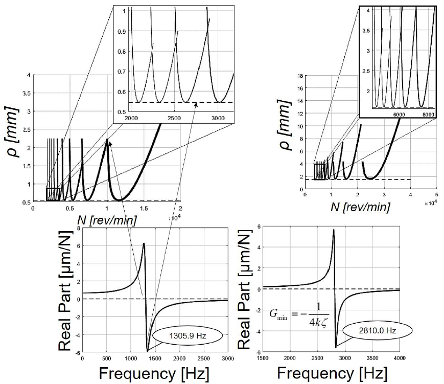
The optimal intersections or points of the consecutive series of lobes provide the optimum depth of cut. The results show that the intersection of the larger lobes (on the right of the diagram), provides a stable machining at the highest spindle speed, as well as the deepest depth of cut. A compromise is made between the spindle speed and the depth of cut for the smaller lobes (on the left of the diagram), where the spindle speed is lower. The location of these lobes depends on the mechanical properties of the PKM.
5. Conclusions
Improving the machining stability has been an interest of research in recent years. This article extends chatter stability analysis to a decoupled parallel kinematic machine. The features that make it suitable for machining tasks are highlighted. Chatter vibration can be completely prevented calculating the stability lobes diagrams. As a case study, the stability charts for a decoupled parallel kinematic machine are simulated and it is demonstrated that in high-speed machining local modes of the spindle-toolholder-tool subsystem are excited because the tooth passing frequency is high above the modal frequencies of the machine structure. The theoretical model derived in this work can be used to allow the machine operators to practically choose the cutting parameters, trainers to effectively teach the chatter theory, and beginners to easily create stability lobe diagrams and practice optimizing cutting parameters.

