


 nueva página del texto (beta)
 Inglés (pdf)
 Artículo en XML
 Referencias del artículo
 Enviar artículo por email
 Citado por SciELO
  Similares en
SciELO
Similares en
SciELO 
 Permalink
1. Introduction
Data from the Chartered Institute of Traffic and Logistic in Nigeria (CITLN), corroborated by the Federal Road Safety Commission of Nigeria (FRCN) reveals that more than seven million vehicles operate on Nigerian roads on a daily bases (Osigwe, Oladipo & Onibere, 2011). Among these vehicles are medical ambulances, fire service vans, Central Bank of Nigeria (CBN) bullion vans, convoys of military, Para-military and sometimes political elites’ convoys, etc. In most cases, these groups of special road users or emergency vehicles are accorded special right of ways especially at the road junctions. On the believe that they always have the right of ways, these groups of special road users tend to maneuver their ways through traffic jams at junctions even when the traffic light is displaying RED. In most cases, pedestrians are cut in the web of conflicting authority between the green light for the pedestrians and the movement of emergency vehicles across road junctions. These scenarios had resulted in compounded traffic jams and in most cases fatal accidents.
The road networks in major cities of Nigeria are now well organized with traffic lights at the majority of the t-road and cross-road junctions. In the city of Enugu, for instance, all the traffic lights systems are of the conventional type that are based on fixed time concept allotted to each side of the junction which cannot be varied in consonance with varying traffic density. Junction timings allotted are fixed. Sometimes, however, higher traffic density at one side of the junction demands longer green time as compared to standard allotted time. The conventional type of traffic lights systems fall short of being efficient since they are unable to handle various simple situations that arise throughout the day resulting in unnecessary waiting time (Thunig, Scheffier & Nagel, 2019).
To avert the long queues, unnecessary loss of man-hour and vehicular accidents especially at the road junctions in Enugu metropolis, the intelligent traffic light control system is proposed in this paper. The intelligent traffic light control system has the capacity to detect any lane in a t-road or cross-road junction with higher density of vehicles and allot to it the right of way and blocking every other lane with less density of vehicles. In addition and most importantly, it has a remote control facility to override the set timing by providing instantaneous green signal in the desired direction while blocking the other lanes by red signal for some time (Ganiyu, Olabiyisi, Omidiora, Okediran & Alo, 2011; Jaiswal, Agarwal, Singh & Lakshita, 2013; Mainali & Mabu, 2010; Li et al., 2009). The remote control overriding authority may usually be vested only on the FRCN officials and the special road users to override the set timing in the event of emergencies.
2. Review of related work
The conventional traffic light that are in widespread use today are devoid of intricate reasoning to decide when to change the lights for the various road users waiting in different lanes. Several works on intelligent and dynamic traffic monitoring systems aimed at remedying the consequential effects of the fixed-time traffic control systems have been carried out in recent years. Genetic algorithm approach is used by Li et al. (2009), to estimate the traffic volume in road sections without the traffic information on road sections, where estimation is done using the known traffic volume information of the road sections. The proposed method is evaluated under static environments using a grid road network with various unknown rates of traffic volumes. Experimental results show that the proposed method can estimate the unknown traffic volume using only the known traffic volumes. In Ganiyu et al. (2011), performance evaluation study was carried out by utilizing the existing vehicle-based sensors in taxies for traffic monitoring and vehicle density calculation in order to reduce traffic congestion. Here, two types of traffic status-estimation algorithms, i.e., the link-based and the vehicle-based, are introduced and analyzed with results that show that estimations of the traffic status based on these imperfect data are reasonably accurate.
Focusing in modeling traffic light controlled intersections, a Timed Coloured Petri Net (TCPN) formalism is employed by Jaiswal et al. (2013) to model and simulate a multi-phase traffic light controlled intersection with an associated fixed signal timing plan using T-type junction located in Federal Capital Territory, Abuja, Nigeria, as a case study. Here, the developed model is simulated via CPN tools while its validation is carried out on the basis of real traffic data measured by detectors positioned at each input link of the T-type junction under consideration.
An intelligent traffic control unit for a four way lane crossing of real time scenario is implemented by Dakhole and Moon (2013). Radio-frequency identification (RFID) sensor attached to ambulance is used for the purposes of automatic identification and tracking while IR transmitter and receiver are used to provide dynamic traffic control for the priority vehicles and traffic density control and thus increasing the duration of the Green light of the lane in which priority vehicles or traffic density is high and hence, preventing traffic congestion and regulating traffic.
Based on ARM7 and ATmega16 in conjunction with global positioning system and CC2500 RF module, an intelligent traffic control system was designed by Pable and Welekar (2014). The ARM7 based traffic control system proposes a multiple traffic light control and monitoring system that reduce the possibilities of traffic jams, caused by traffic lights.
The density based signal management system is used to track traffic density at junctions using Road Side Unit (RSU) and control the traffic signals Red and Green indication (Vidhya & Banu, 2014). An RSU is an access points, used together with the vehicles, to collect count of the traffic from number of vehicles to allow information dissemination in the roads. The delay given for Red or Green signal at a square will dynamically determine traffic density by communicating with the vehicles RSU. The uniqueness of this work is that the control is not just based on traffic density calculation but also priority.
The contrasting feature of video based systems over electronic based sensors is the underlining motivation to develop vision based tool for traffic light control (Dong, Xiong & Zhang, 2014). In this architecture camera is placed on top of poles to get the clear view of traffic on the particular side of the lane so that it will capture the image and analyze the traffic in that particular side and get the count of the number of vehicle. The image captured in the traffic signal is processed and converted into grayscale image then its threshold is calculated based on which the contour has been drawn in order to calculate the number of vehicles present in the image to know in which side the density is high based on which signals will be allotted for a particular side. Raspberry pi is used as a microcontroller which provides the signal timing based on the traffic density.
The design and implementation of a real-time traffic light control system based on Field programmable Gate Array (FPGA) technology is reported by Ganiyu, Arulogun and Okediran (2014). The traffic light control system designed with VHDL language was verified with simulation. Subsequently, the VHDL design was downloaded to FPGA board hardware to verify its function in experiment where it was reported that design worked properly as expected.
The use of infra-red (IR) sensors and microcontroller appears to be the trend in intelligent traffic light and density control (Basavaraju, Doddigarla, Naidu & Malgatti, 2104; First & Sinhmar, 2012; Karya & Saranya, 2015; Sharma, Mishra & Singh, 2105). The IR system mounted on either sides of the road (Basavaraju et al., 2014; First & Sinhmar, 2012; Sharma et al., 2105), gets activated whenever any vehicle passes on the road between IR transmitter and IR receiver. The sensors output is sent to a microcontroller then this data is fed to the computer to digitize the output. Microcontroller controls the IR system and counts number of vehicles passing on road, stores vehicles count in its memory and takes decision and updates the traffic light delays as a result. Thus based on vehicle count, microcontroller defines different ranges for traffic light delays and updates those accordingly. In Karya and Saranya (2015), Programmable Integrated Circuit (PIC) 16F84A microcontroller was developed. The PIC is implemented via an IC programmer using a mikrobasic program written in Basic language. The developed traffic light control system is tested by constructing a prototype that resembles the real application. PIC Microcontroller density based traffic signal systems continue to find wide applications (Devi et al., 2017; Saiba, Afeefa, Aruna, Jose & Radhika, 2017). Recent developers of smart traffic signal systems employ different technologies like Arduino (Udoakah & Okure, 2017), surveillance system (Monika, Anuradha & Prasad, 2019) and wireless communications (Vaishali & Jeyapriya, 2017). Intelligent traffic signal systems have recently been developed using other control architectures (Kumari, Patil, Maurya, Phalle & Hule 2018; Usikalu, Okere, Ayanbisi, Adagunodo & Babarimisa, 2019; Wang, Yang, Liang & Liu, 2018).
3. Proposed system
A smart traffic light control system intended for intelligent allocation of right of way based on vehicle densities sensing, allotting of due passage duration time, and overriding feature for emergency cases, is proposed and implemented in this paper. To realize the three set objectives, three PIC 16F877A microcontrollers, one specifically dedicated for each of the three tasks, are deployed for the logic control design. Three PIC16F877A microcontrollers are used to provide enough number of pins for the three tasks. A Proteus Labcenter circuit design of the system was first simulated as shown in Fig. 1 before actual implementation. Each of the microcontrollers is a CMOS FLASH-based 8-bit microcontroller with RISC architecture. The system contains eight pressure (PR) sensors, two each in each of the four roads. The PR sensors are located at a distance between each other such that when both of them experience continuous depression for specified seconds, an overriding signal is logically sent to the microcontroller. To achieve the control design, the microcontrollers are set into operation by writing sets of instructions (using C language) which are assembled and burnt into the microcontroller chip.

4. Phase design
The main aim of the phase design is to differentiate the conflicting movements in an intersection into various phases, so that movements in a phase should have no conflicts. Since all the movements are to be separated with no conflicts, then a large number of phases are required. In such a situation, the main aim is to design phases with minimum or less severe conflicts. There is no precise methodology for the design of phases. This is often guided by the geometry of the intersection, flow pattern especially the turning movements, the relative magnitudes of flow. Therefore, a trial and error procedure is often adopted. However, phase design is very important because it affects the further design steps. For the 4-way road traffic in this design, a model of eight phase signal system is adopted to ensure adequate separation of conflicting movements. The phase designs of the different phases adopted in this paper are illustrated in Figs. 2(a) to 2(h).


The arrow-headed lines in the phase designs indicate the allowed movement for vehicle traffic in a particular phase while the double arrow lines show the permitted movement of pedestrians. The desired cycle of operation is as shown in Fig. 3 in which the sequences with numbers (1, 2, 3, 4) represent sequence of preferential treatment (right of way) given to the four roads while sequences with letters (B, C, D, A) represent the right of way given to pedestrians. This means that for instance, after road 1 users have been given the right of way, the next sequence is that of the pedestrian crossing for road 1 (sequence B). Pedestrian crossing for road 2 ‘sequence C’ is enabled after right of way for the road 2 users ‘sequence 2’. Another cycle of operation begins after pedestrian crossing for road 4 i.e. ‘sequence A’.

From the phase designs and the desired cycle of operation the truth table for the switching sequences can be developed. The truth Table 1 shows only sequences 1 and 2 for vehicular right of ways and sequences B and C for pedestrian right of ways
Table 1 Truth table for the sequences 1, B, 2 and C.
| SEQUENCE | ROADS | G | Y | R | ARROW UP | ARROW RIGHT | PEDESTRIAN |
| SEQUENCE 1 |
ROAD 1 | ON | OFF | OFF | ON | ON | OFF |
| ROAD 2 | OFF | OFF | OFF | OFF | ON | OFF | |
| ROAD 3 | OFF | OFF | OFF | OFF | ON | OFF | |
| ROAD 4 | OFF | OFF | OFF | OFF | ON | OFF | |
|
|
|
|
|
|
|
|
|
| ROAD 1 | OFF | ON | OFF | ON | ON | OFF | |
| ROAD 2 | OFF | ON | OFF | OFF | ON | OFF | |
| ROAD 3 | OFF | ON | OFF | OFF | ON | OFF | |
| ROAD 4 | OFF | ON | OFF | OFF | ON | OFF | |
|
|
|
|
|
|
|
|
|
| ROAD 1 | OFF | OFF | ON | OFF | OFF | OFF | |
| ROAD 2 | OFF | OFF | ON | OFF | OFF | OFF | |
| ROAD 3 | OFF | OFF | ON | OFF | OFF | OFF | |
| ROAD 4 | OFF | OFF | ON | OFF | OFF | OFF | |
| SEQUENCE B |
|
|
|
|
|
|
|
| ROAD 1 | OFF | OFF | ON | OFF | OFF | ON | |
| ROAD 2 | OFF | OFF | OFF | ON | ON | OFF | |
| ROAD 3 | OFF | OFF | OFF | OFF | ON | OFF | |
| ROAD 4 | OFF | OFF | OFF | ON | OFF | OFF | |
| SEQUENCE 2 |
ROAD 1 | OFF | OFF | OFF | OFF | ON | OFF |
| ROAD 2 | ON | OFF | OFF | ON | ON | OFF | |
| ROAD 3 | OFF | OFF | OFF | OFF | ON | OFF | |
| ROAD 4 | OFF | OFF | OFF | OFF | ON | OFF | |
|
|
|
|
|
|
|
|
|
| ROAD 1 | OFF | ON | OFF | OFF | ON | OFF | |
| ROAD 2 | OFF | ON | OFF | ON | ON | OFF | |
| ROAD 3 | OFF | ON | OFF | OFF | ON | OFF | |
| ROAD 4 | OFF | ON | OFF | OFF | ON | OFF | |
|
|
|
|
|
|
|
|
|
| ROAD 1 | OFF | OFF | ON | OFF | OFF | OFF | |
| ROAD 2 | OFF | OFF | ON | OFF | OFF | OFF | |
| ROAD 3 | OFF | OFF | ON | OFF | OFF | OFF | |
| ROAD 4 | OFF | OFF | ON | OFF | OFF | OFF | |
| SEQUENCE C |
|||||||
| ROAD 1 | OFF | OFF | OFF | ON | OFF | OFF | |
| ROAD 2 | OFF | OFF | ON | OFF | OFF | ON | |
| ROAD 3 | OFF | OFF | OFF | ON | ON | OFF | |
| ROAD 4 | OFF | OFF | OFF | OFF | ON | OFF |
5. Control circuit design
Cylindrical tensile specimens were machined from the heat As has been noted earlier, the logic control of this design is realized with the aid of a microcontroller (PIC 16F877A). The import of the three microcontrollers as utilized in this design is to ensure that the three basic aims of this project work- normal traffic control (including timing), density sensing, and application of GSM module, are all achieved in the most effective and efficient manner; troubleshooting becomes easier in case of faults. In order to set the three microcontrollers into operation, a set of instructions is written, assembled and burnt into a Printed Circuit Board (PCB) after the phase design and the truth table had been realized. ‘C language’ is used in writing the codes that satisfies the different phase designs as well as for the density-based sensing and that of the GSM application. Fig. 4 is the circuit board implementation of this work. Of course, the circuit board design was constructed after a real time simulation of the work using Proteus Labcenter software on which it was confirmed to be working perfectly.

6. Switching circuit design
It is important to note that the display unit is powered directly by the power supply unit. This is to ensure that the display unit gets enough power to set it into operation. Also since the current from the I/O pins of the microcontroller is insufficient for the LEDs used for the display unit, it therefore became imperative to power the display unit directly by the PSU. Bearing in mind that the display unit has to be controlled by the logic control unit, a switching circuit is incorporated in a way so as to send instructions to the logic control unit for implementation by the display unit. The principal aim of this switching circuit is to switch the respective signal light to the display unit causing it to come ON and OFF to the satisfaction of the different road phase designs. In this project the switching circuit comprises the Pressure Switch and the SIM 900 GSM module.
6.1 Pressure switch
The pressure switches employed in this design is the push-button switches which act as the mechanical sensors. They are in total, eight push buttons, two per each road. The two push buttons in any given road are usually connected to the inputs of an AND gate. The purpose of the AND gate is to ensure that overriding of traffic flow for a particular road can only be achieved by the depressing of the two push buttons (sensors) simultaneously in any one particular road.
6.2 SIM 900
The GSM application used in this work is known as the SIM 900. It also has the function of overriding the traffic flow thereby giving different road users and pedestrians the right of way.
The GSM module has a slot where a network SIM card is inserted for communication between the PIC and the operator’s cell phone. Fig. 5 is the pictorial view of the SIM 900 showing its antenna and the connected terminals

An MAX232 IC which is a level converter is used to convert logic voltage levels to signals suitable for use in TTL compatible digital logic circuits by the PIC. Therefore when a code is typed from the operators phone, for instance *1#, on getting to the PIC, it performs the function of overriding the traffic flow and automatically giving road 1 users the right of way. Different codes represent different functions that the PIC is supposed to perform. Below is a list of the commands used in this work.
Table 2 Table showing the commands sent to the PIC by the GSM and their meaning.
| COMMAND | MEANING |
| *1# | Right of way for road 1 users |
| *2# | Right of way for road 2 users |
| *3# | Right of way for road 3 users |
| *4# | Right of way for road 4 users |
| *0# | Clears previous instruction in order for a new one to take effect |
In order to confirm that the SIM 900 activates the PIC to perform the overriding function, a code is written for the GSM module in which feedback message is incorporated. Below is the different feedback statements received at operator’s cell phone as the different commands are typed. The GSM module is designed in such a way that it sends the message: ‘Density Based Traffic Control System Using GSM Module’, once the prototype is switched ON.
It is important to note that the outputs of two components that make up the switching circuit: the pressure switches through an AND gate and the SIM 900 are both connected to an OR gate. This is to ensure that the function of traffic override is either performed by the push buttons or the GSM module at any given time.
7. Display unit
This is the unit that displays the required result on LEDs. It consists of the traffic lights which include the red, yellow and green LEDs, the up and right arrows, and the pedestrian LED. In this work, a ‘low’ (sent from the PIC) is used to turn ON the different LEDs of the display unit. This is done by connecting the entire positive electrodes (anode) of the LEDs together to a voltage of 5V without connecting the ground. Normally the cathode of the LED is supposed to see the ground before it works, but the LEDs in this design are connected in such a way that they will light only when the PIC sends a ‘low’ to the negative of the LEDs. The purpose of this is to ensure that the PIC does not get overloaded and burn in the process of constantly sending a ‘high’ of 5V through its I/O pins. Also the intensity of the LEDs is noticed to have a remarkable increase as the PIC sends a ‘low’ to the negative of the LEDs.
8. Signal timing requirement
The period of time for green, red and yellow LED indications for the traffic light is 9 seconds. The “GO” and “STOP” period is 9 seconds. Pedestrian safety is also affected by signal timing. The pedestrian walk signal, which is displayed as soon as the conflicting traffic is shown a red light, is usually interpreted to mean pedestrians may proceed safely across the roadway. This pedestrian “GO” (crossing) time is allotted 7 seconds.
9. System evaluation
The signal timing changes automatically in response to the detection of traffic density at any junction. Pulses are generated in the microcontroller when it receives signals from the switching unit which comprises the PR sensors and GSM module to turn the LEDs ON or OFF according to the program written into it. When both the PR sensors on any particular road (implemented though an AND gate) receive a high, they conduct thus sensing the level of density on the road. Assuming a particular road has many vehicles on it, the PR sensors which are embedded on the road will detect it and go high. When this happens, the light in that particular road turns green based on the code written on the controller. On getting to the level where the output of the PR sensor is low, the light turns yellow (indicating getting ready to stop) so that vehicles will not be overcrowded in a particular junction. The function of the GSM module is to override the traffic in case of emergency. To do this, the module is configured such that when a code is sent to it, it accepts it and sends it directly to the PIC16F877A microcontroller. The PIC interprets the received code and turns the light in that particular road green, allowing vehicles to pass. The outputs of the PR sensors through AND gates are ORed with the output of the GSM module to provide the override in accordance with the density detection or emergency situation as the case may be.
The outputs of the microcontrollers gave the correct signals as programmed and the LEDs arrangements gave optimal brightness and can be seen clearly by approaching vehicles. The density aspect of the system was tested and observed to be working perfectly when the two push buttons for road 1 were simultaneously depressed. Fig. 6 shows that road 1 users were automatically given the right of way with the green light. As well the arrow up and arrow right lights are ON.
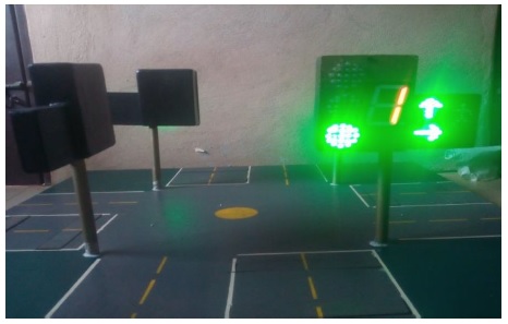
Fig. 7 shows the sequence B cycle of operation giving the right of way to the road 1 pedestrians after the sequence 1. In line with the program that was written, it was observed upon testing that the GSM module was able to send feedback message after a command to override a particular road was typed in the cell phone. The figure below shows the prototype in its full scale work. In line with the program that was written, it was observed upon testing that the GSM module was able to send feedback message after a command to override a particular road was typed in the cell phone. Fig. 8 shows a portion of complete cycle of operation of the prototype.


10. Conclusion
A prototype of a density based traffic light system with GSM based remote override intended as replacement for the cross road junction fixed-time traffic light control system in Enugu metropolis has been designed and implemented. The design is achieved with three PIC 16F877A microcontrollers, one each specifically dedicated for intelligent allocation of right of way based on vehicle densities sensing, allotting of due passage duration time, and overriding feature for emergency cases.
Guided by the geometry of the intersection, flow pattern and the relative magnitudes of flow, phase design was done to differentiate the conflicting movements in the cross road junction. The traffic override is either performed by the push button switches representing the pressure switches for density detections or the GSM module for emergency cases at any given time. A Proteus Labcenter circuit design of the system was first simulated before actual implementation. The traffic override capability of the design was tested and was found to be working properly both in density detection scenario and in emergency situation.

