


 nueva página del texto (beta)
 Inglés (pdf)
 Artículo en XML
 Referencias del artículo
 Enviar artículo por email
 Citado por SciELO
  Similares en
SciELO
Similares en
SciELO 
 Permalink
Introduction
The electromagnetic characteristics of the squirrel cage motor make it the most used prime mover in industry. Methods to estimate motor performance, like equivalent circuits, analytical or numerical representation, are used and techniques to compute some electrical parameters as genetic algorithm and differential evolution are examples of different tools. In any case, it is important to analyse the design and to determine the performance and the motor parameters before manufacture.
Maxwell's equations describe the relationship between electromagnetic variables enabling the temporal and spatial analysis in energy conversion devices. However, due to the motor geometry and the non-linear characteristics of materials, the analysis and design using analytical methods is not an easy task.
The Finite Element Method (FEM) is a tool of great help to solve systems of differential equations in many areas (Castañeda et al., 2020). The essential idea of FEM is to geometrically divide a domain or a body in small subdivisions or elements that are joined by nodes and form an assembly called mesh. The task is to postulate simple equations and assemble the information that comes from each element generating an algebraic system of equations to get the solution of the proposed model.
The study of electromagnetic devices with FEM gives a very close representation of their steady state (Guzman et al., 2015) and transient (Qiu et al., 2020) behaviour. It also helps to visualize and obtain the distribution of magnetic flux density, leakage flux, magnetic field strength, among other variables.
This work includes design elements that have been considered by researchers to tackle different problems. The examined elements are: the pack of ferromagnetic laminations with radial ventilation channels in rotor and stator (Cha et al., 2017; Tong et al., 2018), the magnetic wedges to close slots of the stator pack (Frosini & Pastura, 2020; Yang et al., 2020; Verucchi et al., 2017), the edge effects of the stator winding and of the rotor rings that short-circuited the squirrel cage bars (Jimenez et al., 2016; Kumar et al., 2020). These elements of the squirrel cage motor are all included in the simple 2D FEM model proposed in this paper.
The motivation of this work is to have a methodology to obtain the parameters and simulate the behaviour of large squirrel cage motors (medium and high voltage) using FEM in the design phase, before performing the usual electrical laboratory tests determined by international standards (IEC, 2007; IEEE, 2004). Experimental tests can represent a high mechanical stress and an increase of the motor temperature. In addition, there must be a high level of safety to avoid damage to the motor and do not affect the security of the personnel that performs the tests.
The paper is organized in the following manner. Section 2 gives a brief description of the squirrel cage motor, the equivalent circuit and the elements included in the FEM model. In Section 3, the FEM applied to electromagnetism is presented. Section 4 shows a simple 2D model. Section 5, the electrical characteristics, geometry, boundary conditions and the electromagnetic field periodicity in the motor for the 2D model are commented. In Section 6 several simulations are performed and in order to verify the obtained results are compared with the laboratory tests and finally, section 7 the conclusion of the paper.
Squirrel cage motor
The squirrel cage motor is a device that uses electromagnetic fields to convert electrical energy into mechanical. The stator has a laminated ferromagnetic core with slots where windings are placed and fed with three-phase voltages. The rotor has a squirrel-cage inserted in its slots. The cores are normally constructed with non-grain-oriented silicon steel.
When the motor is loaded, the three phase stator currents produce a magnetic field that rotates at synchronous speed (Ns). The mechanical rotor speed lags the rotating magnetic field and produces a slip (s) proportional to the percentage of the relative speed between synchronous and mechanical speed (Nm). The frequency of the voltages induced in the rotor winding or bars is called “slip frequency”, denoted by fr, obtained by the product of the slip and the stator frequency f e :
Figure 1 shows the steady-state equivalent circuit of the squirrel cage motor. The resistances of stator (R1), rotor (R’2) and the equivalent resistance to magnetic loss (Rc) and the inductances of stator (L1), rotor (L’2) and magnetization (Lm) are the parameters that represent the presence of electromagnetic field linkages and current in conductors. V1 represents the phase voltage.
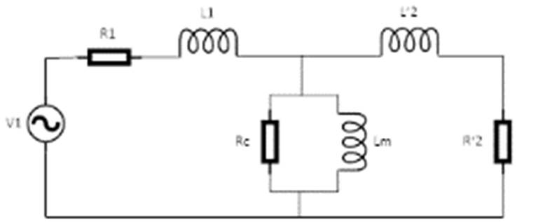
Figure 1 Single-phase equivalent circuit (referred to the stator) of a balanced three-phase squirrel cage motor
The proposed method relates the physical variables of the motor with the equivalent circuit parameters. It uses the FEM to calculate the circuit parameters as well as the equivalent circuit currents.
Radial rotor and stator ventilation ducts
In the FEM, the consideration of the complete geometry of a structure demands expensive computational resources. For this reason, it is convenient to simplify the motor structure. In the case of laminated magnetic cores, the shape of the magnetic sheets and the air between sheets may cause numerical problems, since there is a strong dimensional disproportion between the length of the magnetic core and the thickness of the sheets.
One solution is to model an equivalent macroscopic structure using a homogenization technique, this technique allows simplifying the behavior of a material. Starting from a heterogeneous structure that consists of several materials and can be determined in a homogeneous equivalent structure. This technique requires the use of the magnetic circuit concept.
The geometry of the radial package and vents of the stator and rotor is shown in Figure 2a. The homogeneous permeability is calculated considering a Cartesian system and assuming that the magnetic flux is in the “y” direction. The reluctance presented by the system is a parallel combination of the reluctances of the stack and the radial vents. This is shown in Figure 2b (Salon & Chari, 1999), where:

The reluctance values for air (a) and silicon steel laminated core (i) are:
Where:
|
radial longitude |
|
stack axial length |
|
the permeability of silicon steel laminated core and air, respectively |
Thus, the equivalent permeability(
It can be seen that as the rotor ducts and the stack have the same length (this is also valid for the stator) the equivalent permeability changes depend only on the magnetic permeability.
Magnetic materials in the core
The stator and rotor cores of squirrel cage motors are manufactured with lamination thicknesses of 0.27 to 0.65 mm to avoid eddy or circulating currents. The ferromagnetic laminations are mainly made with iron and alloys, since they offer a better cost-benefit of motor performance. These materials are known as electrical steels, since they are highly permeable. Investigations carried out showed that to improve the electrical characteristics of the steels, around 0.6 % to 3 % of silicon is added and thermal treatments such as annealing and recrystallization are made in order to reduce power losses (eddy and hysteresis) (Liu et al., 2015).
Furthermore, magnetic wedges located in the slots of the stator core are used to improve the performance characteristics, providing a magnetic path that closes the slots and reduces the air gap. Core losses decrease under no load condition and reduce the harmonic content in the spatial distribution of the magnetic flux. It also helps to keep the coils in the slots, particularly during motor starting due to the electrodynamic forces (Verucchi et al., 2017). The magnetic wedge is shown in Figure 3 and its composition is often a mixture of powder iron and a thermosetting resin.

The magnetic B-H characteristic of the core material, as well as the obtained equivalent permeability and the magnetic wedge permeability are shown in Figure 4.

Edge effects
To have a better representation of the squirrel cage motor performance, it is important to consider the leakage flux due to the overhang winding at the end of the magnetic steel pack (Figure 5). To obtain the total leakage flux, it is necessary to determine some parameters such as starting torque, starting current and power factor, among others (Schuhmann et al., 2013).

The solid conductors or bars of the squirrel-cage rotor are short-circuited with
end-rings that have a finite impedance between each bar (Figure 6) (Escarela
et al., 2009). The inductance

There is technical literature (Pyrhonen, 2013) and (Boldea, 2020) that describes how to determine the end winding leakage inductance and to determine the end ring impedance parameters, which are an extension of the model of the stator winding and of the end ring squirrel cage.
Finite element method applied to low-frequency electromagnetism
In electromagnetism, the Maxwell's equations for electric and magnetic fields are expressed as follows:
Where:
|
Vector of electric field strength |
|
Vector of magnetic induction |
|
Vector of magnetic field intensity |
|
Vector of electric displacement or electric induction |
|
Vector of electric current density |
Maxwell's equations are complemented with the constitutive relations that establish the characteristics of the medium: The presence of nonlinearities, remaining inductions, and the behaviour of the fields in the interface between different media, among others.
Where:
In this work, all media are considered isotropic.
There are equivalent formulations, based on vector and scalar, magnetic and electric potentials to implicitly solve the Maxwell's equations. The solution of the differential equations in partial derivatives, in terms of the potentials, represent the solution of the Maxwell's equations. In this problem, the displacement current is negligible as compared to the main current for low frequency operation and therefore it can be omitted (Bastos & Sadowski, 2003).
In this case, the formulation used is the magnetic vector potential (
Simple 2D model
The squirrel cage motors have intricate geometries that require a detailed
analysis. Research performed in (Pechlivanidou
et al., 2019; Fireţeanu et al., 2019) compares 2D and 3D FEM
models showing the differences in the results. Substantially 3D models require
much more computing time than 2D models and the size of the files used in 3D
analyses is 10 times greater than the 2D analyses files. The results of both
techniques have a percentage error that seems to be significant only for a few
electromagnetic quantities, like the torque and the airgap total flux density
where the error is around 8 % between 2D and 3D analyses. A simple 2D model is
proposed to reduce the computing time, simplify the problem, and accomplish a
detailed representation of the geometry. Hence, the magnetic vector potential
and the current density have only one component in the axial direction (
Where
Equations for conductors
Two types of conductors, of different dimensions, are considered in this work: Solid conductors that, due to their large dimensions and the skin effect, do not have a uniform distribution of the current in their cross-section and the filamentary conductors in the winding coils where the current is considered uniformly distributed.
Solid conductors: By modifying equation (10) for solid conductors we get the following relation:
Where:
Vm= |
the potential difference between the conductor terminals |
Rm= |
the DC resistance of the conductor |
Im= |
the total current in the conductor |
S= |
the cross-section of the conductor |
Γ= |
the length of the conductor |
Figure 7 shows the solid conductor

Filamentary conductors: Let Γ be the length, If the current and Nc the number of turns. The conductor has a small cross-section (s) so as to avoid the skin effect. Figure 8 shows the filamentary conductor.

Similarly, as it was for solid conductors, the equation (10), for filamentary conductors is:
Finally, the system of equations for the analysis of low frequency electromagnetic problem is as follows:
An additional term has been introduced in (17):
Squirrel cage motor modeling
This section presents the finite element model of a squirrel cage motor. The considered model assumptions are:
Three-dimensional effects are incorporated using a 2D model of the electromagnetic system complemented with resistances and inductances representing those effects.
In a simple 2D model, an isotropic media is assumed, but nonlinear, which means that the saturation phenomenon is considered.
The dielectric and conductive characteristics are linear, therefore, the permittivity of the material (
Main specifications of simulated motor
Table 1 Specifications of the motor
| Motor type | Three phases |
| Rated power, Pn | 1400 hp |
| Nominal supply voltage, Vfn | 7200 V (Line voltage) |
| Connection type | Star |
| Electrical frequency, fe | 60 Hz |
| Length of the stator and rotor magnetic core | 830 mm |
| External diameter of the stator magnetic core | 690 mm |
| Internal diameter of the stator | 420 mm |
| Length of the air gap | 2.4 mm |
| Pole pairs number | 2 |
| Number of stator sots | 48 |
| Number of rotor sots | 58 |
| Parallel branches | 2 |
| Turns in series in a stator coil | 8 |
| Stator slot pitch | 12 |

Periodicity and boundary conditions
In the studied motor, it is used a periodicity condition due to its symmetry that
delimits the boundaries of periodic portions with equal potential values, and to
solve equation (10), boundary conditions must be considered. The boundaries that
define the selected domain are the stator core outer periphery and the rotor
core inner periphery. The evaluation of the electromagnetic field in all FEM
simulations considers the magnetic vector potential A
z
as unknown in the whole domain. The Dirichlet condition is considered in
this boundary as no magnetic flux is crossing it:
Simulations results
The simulations presented in this work result from a time-harmonic analysis performed in a commercial FEM software (Altair, 2016) at constant slip values (rotor speed constant values) and do not consider the movement of the rotor with respect to the stator. It is important to point out that the results do not depend on FEM software used, the important thing is to considerer the characteristics mentioned in this paper to obtain accurate results close to the real motor.
The frequency in the rotor circuit is adjusted according to equation (1). In Figure 10 the results are shown graphically for a complete speed range.

Full load simulation
These simulations contain the motor characteristics for a steady-state operation. In Table 2, electrical parameters as the nominal current (I1n), nominal rotation (nn), nominal slip (sn), nominal torque (Tn) and nominal power factor (cosθn) are presented and the results show a good accuracy (less than 1.2 % relative error) between the simulations and the laboratory values.
Table 2 Comparison of values obtained from simulation and laboratory data
| Parameters | I1n (A) | nn (rpm) | sn | Tn (Nm) | cosθn |
| Simulation values | 99.0 | 1789.7 | 0.0057 | 5590 | 0.86 |
| Laboratory values | 99.8 | 1789.6 | 0.00577 | 5597 | 0.87 |
| Percent relative error | 0.8 | 0.005 | 1.2 | 0.12 | 1.1 |
In Table 3, the power balance in the squirrel cage motor motor is shown. Specifically, the electrical input (P1n), Joule losses in stator winding (Pj1n), core loss (Pmn), Joule losses in rotor winding (Pj2n) and efficiency (ηn) are presented. In almost all the calculated values, the obtained relative error is low (less than 1.7 %). Only for the case of core losses the relative error was 4.16 %, in this work the Berttoti formula (Bertotti, 1998) was used to calculate them.
Table 3 Comparison of values obtained from simulation and laboratory data
| Parameters | P1n (W) | Pj1n (W) | Pmn (W) | P2n (W) | ηn (%) |
| Simulation values | 1074853 | 9596 | 11000 | 1045589 | 97.56 |
| Laboratory values | 1087580 | 9700 | 10560 | 1044180 | 96.01 |
| Percent relative error | 1.17 | 1.07 | 4.16 | 0.13 | 1.61 |
Figure 11 shows the lines of the magnetic field forming two poles. The machine under study is a 4 pole (for symmetry only two poles are shown).

Blocked-rotor simulation
The blocked rotor operation is simulated with a slip s=1 and the motor is supplied with a reduced voltage from 15 % to 30 % of the nominal value. For the rated current 98.4 A, an applied voltage of 866 V corresponds to an active power of 30747 W.
The distribution of the magnetic field density can be seen in Figure 12. As the slip is equal to one, the frequency of the rotor is the same as the frequency of the source. Therefore, the skin effect in the rotor bars is more pronounced in this condition than when it operates at full load.

In Figure 13, the current density in the bars is shown. As the currents are induced in the rotor bars, a secondary magnetic field is produced which opposes the primary magnetic field due to the skin effect.

No-load simulation
The simulation at no-load is performed with s=0.001, since it represents a slip value much less than the nominal slip. The objective of this simulation is to calculate the currents at no-load, when the motor is fed at nominal voltage. For a slip value s=0.001 at no-load the stator current corresponds to Ioc =34.7A and the value of the power loss in the magnetic core is Poc=11,111 W.
Calculation of the parameters of single-phase equivalent circuit of the three-phase squirrel cage motor
The equivalent circuit parameters of the motor are calculated from the results of simulations at no-load and blocked rotor (Umans, 2014). From the simulation of the motor operation at no-load, the magnetization reactance and the equivalent resistance due to the losses in the iron can be calculated. From the locked rotor simulation, the rotor resistance and the leakage inductance referred to the stator are obtained.
Table 4 presents the values of the parameters of the equivalent circuit of the modelled induction machine.
Table 4 Equivalent circuit parameters of the simulated induction machine
| Parameters | R1 (Ω) | L1 (mH) | Rc (kΩ) | Lm (mH) | R'2 (Ω) | L'2 (mH) |
| Values | 0.33 | 11.6 | 4.67 | 318 | 0.73 | 11.64 |
Since the parameters that were obtained from the simulations performed by the FEM (Table 4) and the analysis of Thevenin's theorem applied to the equivalent circuit of the induction machine (Umans, 2014), the obtained speed-torque curves are shown in Figure 14

In Figure 14 it can be observed an appreciable difference between electromagnetic torque obtained by FEM and with the equivalent circuit. This is mainly due to the fact that the curve obtained with the FEM considers the non-linearity of magnetic materials and does not neglect the effects of eddy currents.
Thevenin’s theorem can be used to calculate some values of the motor starting parameters such as the electromechanical torque and the starting current. However, in order to obtain more precise parameters values, that actually catch the start-up phenomenon, authors suggest performing a transitory analysis.
Conclusion
This paper provides a model of a three-phase squirrel cage motor of 1400 hp using the finite element method. Several simulations were carried out at the frequency domain which made possible to obtain the accurate electromagnetic performance and reliable parameters of the motor equivalent circuit. In the proposed quasi-3D FEM model important physical aspects such as radial ventilation ducts, magnetic wedges and edge effects of the machine were considered. Periodicity and boundary conditions were also selected keeping in view the efficiency of the program.
The theory behind the method was developed using a deep analysis of the electromagnetic equations that made possible to perform the modelling of the squirrel cage motor. Using valid assumptions, a formulation with the vector magnetic potential was obtained (non-linear diffusion equation). In principle, this equation cannot be solved directly since it has two unknowns: the vector magnetic potential and the scalar electric potential. However, to obtain the scalar electric potential, the equations of the massive and filamentary conductors were used that allow the interconnection with external devices, thus solving a circuit-field problem.
The analysis performed includes a complete overview of the input-output variables of a squirrel cage motor as well as the equivalent circuit parameters, i.e. voltages and currents in stator and rotor. Also, internal variables, such as the magnetic field and the magnetic field density are obtained at different operation characteristics and using a shorter computing time than a 3D model. Obtained results were validated with experimental data, which show acceptable percentages of error. This work can help design engineers to calculate the operational properties and features of the induction machine with a high reliability and without the need to build a previous prototype.

